2006 MERCEDES-BENZ SPRINTER check engine light
[x] Cancel search: check engine lightPage 828 of 2305
COOLING
TABLE OF CONTENTS
page page
COOLING
OPERATION - COOLING SYSTEM...........1
DIAGNOSIS AND TESTING
DIAGNOSIS AND TESTING - PRELIMINARY
CHECKS.............................1COOLING SYSTEM.....................2
ACCESSORY DRIVE.......................5
ENGINE.................................9
COOLING
OPERATION - COOLING SYSTEM
The cooling system regulates engine operating tem-
perature. It allows the engine to reach normal oper-
ating temperature as quickly as possible. It also
maintains normal operating temperature and pre-
vents overheating.
The cooling system also provides a means of heat-
ing the passenger compartment and cooling the auto-
matic transmission fluid (if equipped). The cooling
system is pressurized and uses a centrifugal water
pump to circulate coolant throughout the system.
DIAGNOSIS AND TESTING
DIAGNOSIS AND TESTING - PRELIMINARY
CHECKS
ENGINE COOLING SYSTEM OVERHEATING
Establish what driving conditions caused the com-
plaint. Abnormal loads on the cooling system such as
the following may be the cause:
²PROLONGED IDLE
²VERY HIGH AMBIENT TEMPERATURE
²SLIGHT TAIL WIND AT IDLE
²SLOW TRAFFIC
²TRAFFIC JAMS
²HIGH SPEED OR STEEP GRADES
Driving techniques that avoid overheating are:
²Idle with A/C off when temperature gauge is at
end of normal range.²Increasing engine speed for more air flow is rec-
ommended.
TRAILER TOWING:
Consult Trailer Towing section of owners manual.
Do not exceed limits.
AIR CONDITIONING; ADD - ON OR AFTER MARKET:
A maximum cooling package should have been
ordered with vehicle if add-on or after market A/C is
installed. If not, maximum cooling system compo-
nents should be installed for model involved per
manufacturer's specifications.
RECENT SERVICE OR ACCIDENT REPAIR:
Determine if any recent service has been per-
formed on vehicle that may effect cooling system.
This may be:
²Engine adjustments (incorrect timing)
²Slipping engine accessory drive belt(s)
²Brakes (possibly dragging)
²Changed parts. Incorrect water pump or pump
rotating in wrong direction due to belt not correctly
routed
²Reconditioned radiator or cooling system refill-
ing (possibly under filled or air trapped in system).
NOTE: If investigation reveals none of the previous
items as a cause for an engine overheating com-
plaint, (Refer to 7 - COOLING - DIAGNOSIS AND
TESTING)
VACOOLING 7 - 1
Page 837 of 2305
Propylene - glycol / Ethylene - glycol Mixtures - Should Not
Be Used in Chrysler Vehicles
Propylene-glycol/ethylene-glycol Mixtures can
cause the destabilization of various corrosion inhibi-
tors, causing damage to the various cooling system
components. Also, once ethylene-glycol and propy-
lene-glycol based coolants are mixed in the vehicle,
conventional methods of determining freeze point will
not be accurate. Both the refractive index and spe-
cific gravity differ between ethylene glycol and propy-
lene glycol.
CAUTION: Richer antifreeze mixtures cannot be
measured with normal field equipment and can
cause problems associated with 100 percent ethyl-
ene-glycol.
DIAGNOSIS AND TESTING
COOLING SYSTEM LEAKS
ULTRAVIOLET LIGHT METHOD
A leak detection additive is available through the
parts department that can be added to cooling sys-
tem. The additive is highly visible under ultraviolet
light (black light). Pour one ounce of additive into
cooling system. Place heater control unit in HEAT
position. Start and operate engine until radiator
upper hose is warm to touch. Aim the commercially
available black light tool at components to be
checked. If leaks are present, black light will cause
additive to glow a bright green color.
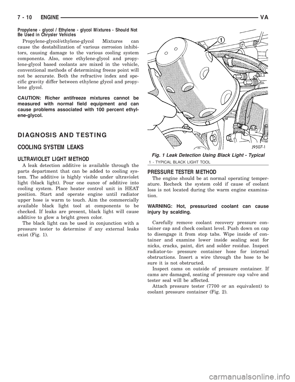
The black light can be used in conjunction with a
pressure tester to determine if any external leaks
exist (Fig. 1).
PRESSURE TESTER METHOD
The engine should be at normal operating temper-
ature. Recheck the system cold if cause of coolant
loss is not located during the warm engine examina-
tion.
WARNING: Hot, pressurized coolant can cause
injury by scalding.
Carefully remove coolant recovery pressure con-
tainer cap and check coolant level. Push down on cap
to disengage it from stop tabs. Wipe inside of con-
tainer and examine lower inside sealing seat for
nicks, cracks, paint, dirt and solder residue. Inspect
radiator-to- pressure container hose for internal
obstructions. Insert a wire through the hose to be
sure it is not obstructed.
Inspect cams on outside of pressure container. If
cams are damaged, seating of pressure cap valve and
tester seal will be affected.
Attach pressure tester (7700 or an equivalent) to
coolant pressure container (Fig. 2).
Fig. 1 Leak Detection Using Black Light - Typical
1 - TYPICAL BLACK LIGHT TOOL
7 - 10 ENGINEVA
Page 838 of 2305

Operate tester pump to apply 103.4 kPa (15 psi)
pressure to system. If hoses enlarge excessively or
bulges while testing, replace as necessary. Observe
gauge pointer and determine condition of cooling sys-
tem according to following criteria:
Holds Steady:If pointer remains steady for two
minutes, serious coolant leaks are not present in sys-
tem. However, there could be an internal leak that
does not appear with normal system test pressure. If
it is certain that coolant is being lost and leaks can-
not be detected, inspect for interior leakage or per-
form Internal Leakage Test.
Drops Slowly:Indicates a small leak or seepage
is occurring. Examine all connections for seepage or
slight leakage with a flashlight. Inspect radiator,
hoses, gasket edges and heater. Seal small leak holes
with a Sealer Lubricant (or equivalent). Repair leak
holes and inspect system again with pressure
applied.
Drops Quickly:Indicates that serious leakage is
occurring. Examine system for external leakage. If
leaks are not visible, inspect for internal leakage.
Large radiator leak holes should be repaired by a
reputable radiator repair shop.
INTERNAL LEAKAGE INSPECTION
Remove engine oil pan drain plug and drain a
small amount of engine oil. If coolant is present in
the pan, it will drain first because it is heavier than
oil. An alternative method is to operate engine for a
short period to churn the oil. After this is done,
remove engine dipstick and inspect for water glob-ules. Also inspect transmission dipstick for water
globules and transmission fluid cooler for leakage.
WARNING: WITH RADIATOR PRESSURE TESTER
TOOL INSTALLED ON RADIATOR, DO NOT ALLOW
PRESSURE TO EXCEED 110 KPA (20 PSI). PRES-
SURE WILL BUILD UP QUICKLY IF A COMBUSTION
LEAK IS PRESENT. TO RELEASE PRESSURE,
ROCK TESTER FROM SIDE TO SIDE. WHEN
REMOVING TESTER, DO NOT TURN TESTER MORE
THAN 1/2 TURN IF SYSTEM IS UNDER PRESSURE.
Operate engine without pressure cap on coolant
container until thermostat opens. Attach a Pressure
Tester to container. If pressure builds up quickly it
indicates a combustion leak exists. This is usually
the result of a cylinder head gasket leak or crack in
engine. Repair as necessary.
If there is not an immediate pressure increase,
pump the Pressure Tester. Do this until indicated
pressure is within system range of 110 kPa (16 psi).
Fluctuation of gauge pointer indicates compression or
combustion leakage into cooling system.
Because the vehicle is equipped with a catalytic
converter,do notremove spark plug cables or short
out cylinders to isolate compression leak.
If the needle on dial of pressure tester does not
fluctuate, race engine a few times to check for an
abnormal amount of coolant or steam. This would be
emitting from exhaust pipe. Coolant or steam from
exhaust pipe may indicate a faulty cylinder head gas-
ket, cracked engine cylinder block or cylinder head.
A convenient check for exhaust gas leakage into
cooling system is provided by a commercially avail-
able Block Leak Check tool. Follow manufacturers
instructions when using this product.
COMBUSTION LEAKAGE TEST - WITHOUT PRES-
SURE TESTER
DO NOT WASTE reusable coolant. If solution is
clean, drain coolant into a clean and suitably marked
container for reuse.
WARNING: Do not remove cylinder block drain
plugs or loosen radiator drain with system hot and
under pressure. serious burns from coolant can
occur.
Drain sufficient coolant to allow thermostat
removal.
Remove accessory drive belt.
Add coolant to pressure container to bring level to
within 6.3 mm (1/4 in) of top of thermostat housing.
CAUTION: Avoid overheating. Do not operate
engine for an excessive period of time. Open drain-
cock immediately after test to eliminate boil over.
Fig. 2 PRESSURE TESTING
1 - PRESSURE RESERVOIR CAP
2 - PRESSURE RESERVOIR
3 - PRESSURE TESTER
VAENGINE 7 - 11
Page 846 of 2305

(17) Take off charge air cooler together with cool-
ing loop of the steering at the radiator (Fig. 10).
(18) Remove bottom radiator trim (Fig. 10).
(19) Detach coolant hose at radiator.
(20) Detach coolant pipe together with coolant
hose at the fan shroud.
(21) Remove radiator fan shroud (Fig. 10).
INSTALLATION
(1) Install fan shroud to radiator (Fig. 10).
(2) Attach coolant pipe with hoses to fan shroud
(Fig. 10).
(3) Attach coolant hose at radiator (Fig. 10).
(4) Install bottom radiator trim (Fig. 10).
(5) Install charge air cooler along with cooling loop
of the power steering, to radiator (Fig. 10).
(6) Install radiator assembly into the rubber grom-
mets (Fig. 9).
(7) Install both right and left side radiator trim
panels (Fig. 9).
(8) Attach the transmission cooler lines (Fig. 9).
(9) Attach coolant hose to the bottom right of the
radiator (Fig. 9).
(10) Attach both power steering hydraulic lines
(Fig. 9).
(11) Connect coolant level sensor electrical connec-
tor (Fig. 9).
(12) Connect coolant hoses to the coolant reservoir,
radiator and water pump (Fig. 9).(13) Attach air intake pipe at the body.
(14) Attach charge air hose at air intake.
(15) Attach charge air hose at turbocharger.
(16) Install A/C condenser.
(17) Install front bumper.
(18) Install front end cross member.
(19) Refill power steering to proper level.
(20) Refill transmission to proper level.
(21) Close radiator drain plug and refill the cooling
system (Refer to 7 - COOLING/ENGINE/COOLANT -
STANDARD PROCEDURE).
(22) Recharge air conditioning (Refer to 24 -
HEATING & AIR CONDITIONING/PLUMBING -
STANDARD PROCEDURE).
(23) Run engine until warm and check for leaks.
RADIATOR PRESSURE CAP
DESCRIPTION
All vehicles are equipped with a pressure cap (Fig.
11). This cap releases pressure at some point within
a range of 124-145 kPa (18-21 psi). The pressure
relief point (in pounds) is engraved on top of the cap
The cooling system will operate at pressures
slightly above atmospheric pressure. This results in a
higher coolant boiling point allowing increased radi-
ator cooling capacity. The cap contains a spring-
loaded pressure relief valve. This valve opens when
system pressure reaches the release range of 124-145
kPa (18-21 psi).
A rubber gasket seals the radiator filler neck. This
is done to maintain vacuum during coolant cool-down
and to prevent leakage when system is under pres-
sure.
Fig. 10 RADIATOR AND FAN SHROUD
1 - CLIP
2 - SHROUD
3 - RADIATOR
4 - BOTTOM RADIATOR TRIM PANEL
5 - CHARGE AIR COOLER
6 - TOP RADIATOR TRIM PANEL
7 - POWER STEERING COOLER LOOP
VAENGINE 7 - 19
Page 862 of 2305

²Position of selector lever.
²Selected shift range.
²CAN signals.
²Engine Status.
Engine speed limits may be reached in all gears
with full throttle or in kick-down operation. In for-
ward driving, the shift range of the forward gears
can be adjusted by the operator by tipping the selec-
tor lever to the left or right (AutoStick). However, the
TCM features a downshift inhibitor to prevent the
engine from overspeeding.
OPERATION
The transmission control module (TCM) deter-
mines the current operating conditions of the vehicle
and controls the shifting process for shift comfort and
driving situations. It receives this operating data
from sensors and broadcast messages from other
modules.
The TCM uses inputs from several sensors that are
directly hardwired to the controller and it uses sev-
eral indirect inputs that are used to control shifts.
This information is used to actuate the proper sole-
noids in the valve body to achieve the desired gear.
The shift lever assembly (SLA) has several items
that are monitored by the TCM to calculate shift
lever position. The reverse light switch, an integral
part of the SLA, controls the reverse light relay con-
trol circuit. The Brake/Transmission Shift Interlock
(BTSI) solenoid and the park lockout solenoid (also
part of the SLA) are controlled by the TCM.
The ECM and ABS broadcast messages over the
controller area network (CAN C) bus for use by the
TCM. The TCM uses this information, with other
inputs, to determine the transmission operating con-
ditions.
The TCM:
²determines the momentary operating conditions
of the vehicle.
²controls all shift processes.
²considers shift comfort and the driving situation.
The TCM controls the solenoid valves for modulat-
ing shift pressures and gear changes. Relative to the
torque being transmitted, the required pressures are
calculated from load conditions, engine rpm, vehicle
speed, and ATF temperature.
The following functions are contained in the TCM:
²Shift Program
²Downshift Safety
²Torque Converter Lock-Up Clutch.
²Adaptation.
This transmission does not have a TCM relay.
Power is supplied to the SLA and the TCM directly
from the ignition.
The TCM continuously checks for electrical prob-
lems, mechanical problems, and some hydraulic prob-
lems. When a problem is sensed, the TCM stores a
diagnostic trouble code (DTC). Some of these codescause the transmission to go into ªLimp-Inº or
ªdefaultº mode. Some DTCs cause permanent
Limp-In and others cause temporary Limp-In. The
NAG1 defaults in the current gear position if a DTC
is detected, then after a key cycle the transmission
will go into Limp-in, which is mechanical 2nd gear.
Some DTCs may allow the transmission to resume
normal operation (recover) if the detected problem
goes away. A permanent Limp-In DTC will recover
when the key is cycled, but if the same DTC is
detected for three key cycles the system will not
recover and the DTC must be cleared from the TCM
with the DRBIIItscan tool.
TCM SIGNALS
The TCM registers one part of the input signals by
direct inputs, the other part by CAN C bus. In addi-
tion to the direct control of the actuators, the TCM
sends various output signals by CAN C bus to other
control modules.
Selector Lever Position
The TCM monitors the SLA for all shift lever posi-
tions via the CAN bus.
ATF Temperature Sensor
The ATF temperature sensor is a positive temper-
ature co-efficient (PTC) thermistor. It measures the
temperature of the transmission fluid and is a direct
input signal for the TCM. The temperature of the
ATF has an influence on the shifttime and resulting
shift quality. As the temperature rises, resistance
rises, and therefore, the probing voltage is decreas-
ing. Because of its registration, the shifting process
can be optimized in all temperature ranges.
The ATF temperature sensor is wired in series
with the park/neutral contact. The temperature sig-
nal is transmitted to the TCM only when the reed
contact of the park/neutral contact is closed because
the TCM only reads ATF temperature while in any
forward gear, or REVERSE. When the transmission
is in PARK or NEUTRAL, the TCM will substitute
the engine temperature for the ATF temperature.
Starter Interlock
The TCM monitors a contact switch wired in series
with the transmission temperature sensor to deter-
mine PARK and NEUTRAL positions. The contact
switch is open in PARK and NEUTRAL. The TCM
senses transmission temperature as high (switch
supply voltage), confirming switch status as open.
The TCM then broadcasts a message over CAN bus
to confirm switch status. The PCM receives this
information and allows operation of the starter cir-
cuit.
VAELECTRONIC CONTROL MODULES 8E - 7
Page 962 of 2305
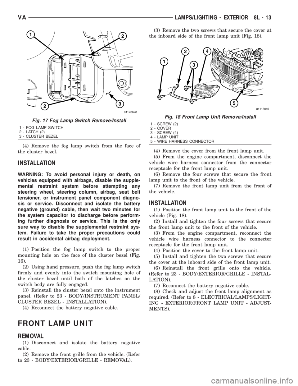
(4) Remove the fog lamp switch from the face of
the cluster bezel.
INSTALLATION
WARNING: To avoid personal injury or death, on
vehicles equipped with airbags, disable the supple-
mental restraint system before attempting any
steering wheel, steering column, airbag, seat belt
tensioner, or instrument panel component diagno-
sis or service. Disconnect and isolate the battery
negative (ground) cable, then wait two minutes for
the system capacitor to discharge before perform-
ing further diagnosis or service. This is the only
sure way to disable the supplemental restraint sys-
tem. Failure to take the proper precautions could
result in accidental airbag deployment.
(1) Position the fog lamp switch to the proper
mounting hole on the face of the cluster bezel (Fig.
16).
(2) Using hand pressure, push the fog lamp switch
firmly and evenly into the switch mounting hole of
the cluster bezel until both of the latches on the
switch body are fully engaged.
(3) Reinstall the cluster bezel onto the instrument
panel. (Refer to 23 - BODY/INSTRUMENT PANEL/
CLUSTER BEZEL - INSTALLATION).
(4) Reconnect the battery negative cable.
FRONT LAMP UNIT
REMOVAL
(1) Disconnect and isolate the battery negative
cable.
(2) Remove the front grille from the vehicle. (Refer
to 23 - BODY/EXTERIOR/GRILLE - REMOVAL).(3) Remove the two screws that secure the cover at
the inboard side of the front lamp unit (Fig. 18).
(4) Remove the cover from the front lamp unit.
(5) From the engine compartment, disconnect the
vehicle wire harness connector from the connector
receptacle for the front lamp unit.
(6) Remove the four screws that secure the front
lamp unit to the front of the vehicle.
(7) Remove the front lamp unit from the front of
the vehicle.
INSTALLATION
(1) Position the front lamp unit to the front of the
vehicle (Fig. 18).
(2) Install and tighten the four screws that secure
the front lamp unit to the front of the vehicle.
(3) From the engine compartment, reconnect the
vehicle wire harness connector to the connector
receptacle for the front lamp unit.
(4) Position the cover to the front lamp unit.
(5) Install and tighten the two screws that secure
the cover at the inboard side of the front lamp unit.
(6) Reinstall the front grille onto the vehicle.
(Refer to 23 - BODY/EXTERIOR/GRILLE - INSTAL-
LATION).
(7) Reconnect the battery negative cable.
(8) Check and adjust the front lamp alignment as
required. (Refer to 8 - ELECTRICAL/LAMPS/LIGHT-
ING - EXTERIOR/FRONT LAMP UNIT - ADJUST-
MENTS).
Fig. 17 Fog Lamp Switch Remove/Install
1 - FOG LAMP SWITCH
2 - LATCH (2)
3 - CLUSTER BEZEL
Fig. 18 Front Lamp Unit Remove/Install
1 - SCREW (2)
2 - COVER
3 - SCREW (4)
4 - LAMP UNIT
5 - WIRE HARNESS CONNECTOR
VALAMPS/LIGHTING - EXTERIOR 8L - 13
Page 1045 of 2305
WIPERS/WASHERS
DESCRIPTION
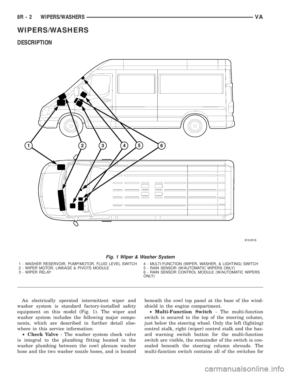
An electrically operated intermittent wiper and
washer system is standard factory-installed safety
equipment on this model (Fig. 1). The wiper and
washer system includes the following major compo-
nents, which are described in further detail else-
where in this service information:
²Check Valve- The washer system check valve
is integral to the plumbing fitting located in the
washer plumbing between the cowl plenum washer
hose and the two washer nozzle hoses, and is locatedbeneath the cowl top panel at the base of the wind-
shield in the engine compartment.
²Multi-Function Switch- The multi-function
switch is secured to the top of the steering column,
just below the steering wheel. Only the left (lighting)
control stalk, right (wiper) control stalk and the haz-
ard warning switch button for the multi-function
switch are visible, the remainder of the switch is con-
cealed beneath the steering column shrouds. The
multi-function switch contains all of the switches for
Fig. 1 Wiper & Washer System
1 - WASHER RESERVOIR, PUMP/MOTOR, FLUID LEVEL SWITCH 4 - MULTI-FUNCTION (WIPER, WASHER, & LIGHTING) SWITCH
2 - WIPER MOTOR, LINKAGE & PIVOTS MODULE 5 - RAIN SENSOR (W/AUTOMATIC WIPERS ONLY)
3 - WIPER RELAY 6 - RAIN SENSOR CONTROL MODULE (W/AUTOMATIC WIPERS
ONLY)
8R - 2 WIPERS/WASHERSVA
Page 1086 of 2305
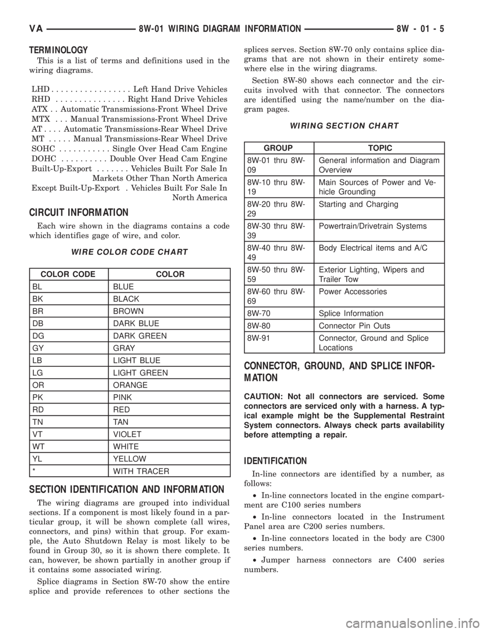
TERMINOLOGY
This is a list of terms and definitions used in the
wiring diagrams.
LHD.................Left Hand Drive Vehicles
RHD ...............Right Hand Drive Vehicles
ATX . . Automatic Transmissions-Front Wheel Drive
MTX . . . Manual Transmissions-Front Wheel Drive
AT....Automatic Transmissions-Rear Wheel Drive
MT .....Manual Transmissions-Rear Wheel Drive
SOHC...........Single Over Head Cam Engine
DOHC..........Double Over Head Cam Engine
Built-Up-Export....... Vehicles Built For Sale In
Markets Other Than North America
Except Built-Up-Export . Vehicles Built For Sale In
North America
CIRCUIT INFORMATION
Each wire shown in the diagrams contains a code
which identifies gage of wire, and color.
WIRE COLOR CODE CHART
COLOR CODE COLOR
BL BLUE
BK BLACK
BR BROWN
DB DARK BLUE
DG DARK GREEN
GY GRAY
LB LIGHT BLUE
LG LIGHT GREEN
OR ORANGE
PK PINK
RD RED
TN TAN
VT VIOLET
WT WHITE
YL YELLOW
* WITH TRACER
SECTION IDENTIFICATION AND INFORMATION
The wiring diagrams are grouped into individual
sections. If a component is most likely found in a par-
ticular group, it will be shown complete (all wires,
connectors, and pins) within that group. For exam-
ple, the Auto Shutdown Relay is most likely to be
found in Group 30, so it is shown there complete. It
can, however, be shown partially in another group if
it contains some associated wiring.
Splice diagrams in Section 8W-70 show the entire
splice and provide references to other sections thesplices serves. Section 8W-70 only contains splice dia-
grams that are not shown in their entirety some-
where else in the wiring diagrams.
Section 8W-80 shows each connector and the cir-
cuits involved with that connector. The connectors
are identified using the name/number on the dia-
gram pages.
WIRING SECTION CHART
GROUP TOPIC
8W-01 thru 8W-
09General information and Diagram
Overview
8W-10 thru 8W-
19Main Sources of Power and Ve-
hicle Grounding
8W-20 thru 8W-
29Starting and Charging
8W-30 thru 8W-
39Powertrain/Drivetrain Systems
8W-40 thru 8W-
49Body Electrical items and A/C
8W-50 thru 8W-
59Exterior Lighting, Wipers and
Trailer Tow
8W-60 thru 8W-
69Power Accessories
8W-70 Splice Information
8W-80 Connector Pin Outs
8W-91 Connector, Ground and Splice
Locations
CONNECTOR, GROUND, AND SPLICE INFOR-
MATION
CAUTION: Not all connectors are serviced. Some
connectors are serviced only with a harness. A typ-
ical example might be the Supplemental Restraint
System connectors. Always check parts availability
before attempting a repair.
IDENTIFICATION
In-line connectors are identified by a number, as
follows:
²In-line connectors located in the engine compart-
ment are C100 series numbers
²In-line connectors located in the Instrument
Panel area are C200 series numbers.
²In-line connectors located in the body are C300
series numbers.
²Jumper harness connectors are C400 series
numbers.
VA8W-01 WIRING DIAGRAM INFORMATION 8W - 01 - 5