2006 MERCEDES-BENZ SPRINTER check engine light
[x] Cancel search: check engine lightPage 659 of 2305
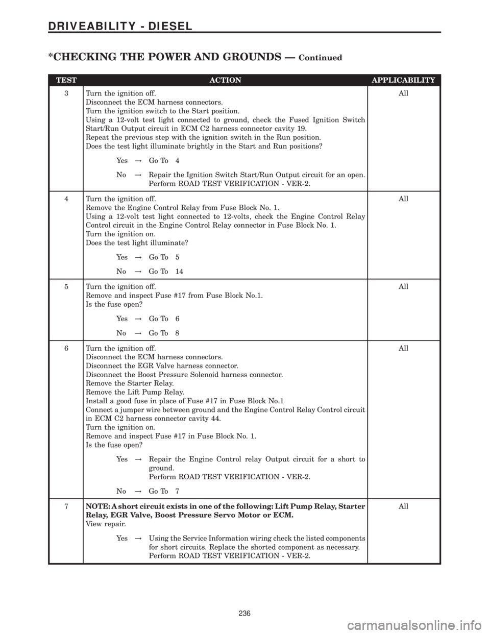
TEST ACTION APPLICABILITY
3 Turn the ignition off.
Disconnect the ECM harness connectors.
Turn the ignition switch to the Start position.
Using a 12-volt test light connected to ground, check the Fused Ignition Switch
Start/Run Output circuit in ECM C2 harness connector cavity 19.
Repeat the previous step with the ignition switch in the Run position.
Does the test light illuminate brightly in the Start and Run positions?All
Ye s!Go To 4
No!Repair the Ignition Switch Start/Run Output circuit for an open.
Perform ROAD TEST VERIFICATION - VER-2.
4 Turn the ignition off.
Remove the Engine Control Relay from Fuse Block No. 1.
Using a 12-volt test light connected to 12-volts, check the Engine Control Relay
Control circuit in the Engine Control Relay connector in Fuse Block No. 1.
Turn the ignition on.
Does the test light illuminate?All
Ye s!Go To 5
No!Go To 14
5 Turn the ignition off.
Remove and inspect Fuse #17 from Fuse Block No.1.
Is the fuse open?All
Ye s!Go To 6
No!Go To 8
6 Turn the ignition off.
Disconnect the ECM harness connectors.
Disconnect the EGR Valve harness connector.
Disconnect the Boost Pressure Solenoid harness connector.
Remove the Starter Relay.
Remove the Lift Pump Relay.
Install a good fuse in place of Fuse #17 in Fuse Block No.1
Connect a jumper wire between ground and the Engine Control Relay Control circuit
in ECM C2 harness connector cavity 44.
Turn the ignition on.
Remove and inspect Fuse #17 in Fuse Block No. 1.
Is the fuse open?All
Ye s!Repair the Engine Control relay Output circuit for a short to
ground.
Perform ROAD TEST VERIFICATION - VER-2.
No!Go To 7
7NOTE: A short circuit exists in one of the following: Lift Pump Relay, Starter
Relay, EGR Valve, Boost Pressure Servo Motor or ECM.
View repair.All
Ye s!Using the Service Information wiring check the listed components
for short circuits. Replace the shorted component as necessary.
Perform ROAD TEST VERIFICATION - VER-2.
236
DRIVEABILITY - DIESEL
*CHECKING THE POWER AND GROUNDS ÐContinued
Page 660 of 2305

TEST ACTION APPLICABILITY
8 Turn the ignition off.
Remove and inspect Fuse #16 from Fuse Block No.1
Is the fuse open?All
Ye s!Go To 9
No!Go To 11
9 Turn the ignition off.
Disconnect the ECM harness connectors.
Install a good fuse in place of Fuse #16 in Fuse Block No.1
Connect a jumper wire between ground and the Engine Control Relay Control circuit
in ECM C2 harness connector cavity 44.
Remove and inspect Fuse #16 from Fuse Block No.1.
Is the fuse open?All
Ye s!Repair the Engine Control Relay Output circuit for a short to
ground.
Perform ROAD TEST VERIFICATION - VER-2.
No!Go To 10
10 The Fuel Injectors, Crankcase Heater, Water In Fuel Sensor and related circuits can
cause Fuse #16 in Fuse Block No.1 to open. Use the Service Information Wiring
Diagrams and check these circuits/components for shorted circuits.
Were any problems found.All
Ye s!Repair or replace shorted circuit/component as necessary.
Perform ROAD TEST VERIFICATION - VER-2.
No!Replace and program the ECM in accordance with the Service
Information.
Perform ROAD TEST VERIFICATION - VER-2.
11 Turn the ignition off.
Disconnect the ECM harness connectors.
Connect a jumper wire between ground and the Engine Control Relay Control circuit
in ECM C2 harness connector cavity 44.
Turn the ignition on.
Using a 12-volt test light connected to ground, check the Fused Engine Control Relay
Output circuits at the ECM C2 harness connector cavities 1, 3 and 5.
Choose the appropriate result.All
Test light is on for all circuits.
Test Complete.
Test light is on for 1 or 2 circuits
Repair the Engine Control Relay Output circuit(s) for an open.
Perform ROAD TEST VERIFICATION - VER-2.
Light off for all circuits.
Go To 12
237
DRIVEABILITY - DIESEL
*CHECKING THE POWER AND GROUNDS ÐContinued
Page 661 of 2305
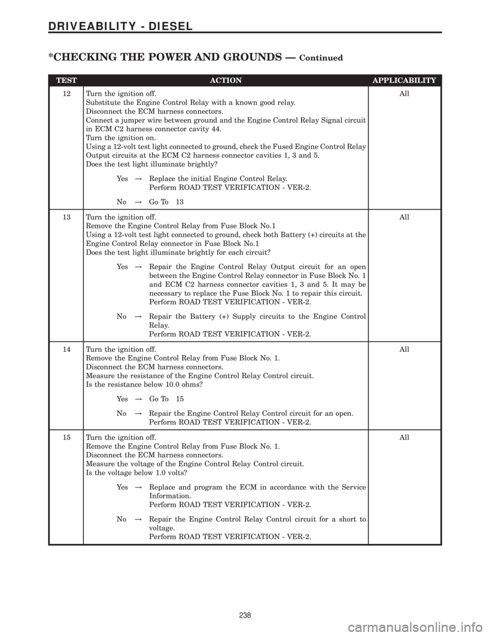
TEST ACTION APPLICABILITY
12 Turn the ignition off.
Substitute the Engine Control Relay with a known good relay.
Disconnect the ECM harness connectors.
Connect a jumper wire between ground and the Engine Control Relay Signal circuit
in ECM C2 harness connector cavity 44.
Turn the ignition on.
Using a 12-volt test light connected to ground, check the Fused Engine Control Relay
Output circuits at the ECM C2 harness connector cavities 1, 3 and 5.
Does the test light illuminate brightly?All
Ye s!Replace the initial Engine Control Relay.
Perform ROAD TEST VERIFICATION - VER-2.
No!Go To 13
13 Turn the ignition off.
Remove the Engine Control Relay from Fuse Block No.1
Using a 12-volt test light connected to ground, check both Battery (+) circuits at the
Engine Control Relay connector in Fuse Block No.1
Does the test light illuminate brightly for each circuit?All
Ye s!Repair the Engine Control Relay Output circuit for an open
between the Engine Control Relay connector in Fuse Block No. 1
and ECM C2 harness connector cavities 1, 3 and 5. It may be
necessary to replace the Fuse Block No. 1 to repair this circuit.
Perform ROAD TEST VERIFICATION - VER-2.
No!Repair the Battery (+) Supply circuits to the Engine Control
Relay.
Perform ROAD TEST VERIFICATION - VER-2.
14 Turn the ignition off.
Remove the Engine Control Relay from Fuse Block No. 1.
Disconnect the ECM harness connectors.
Measure the resistance of the Engine Control Relay Control circuit.
Is the resistance below 10.0 ohms?All
Ye s!Go To 15
No!Repair the Engine Control Relay Control circuit for an open.
Perform ROAD TEST VERIFICATION - VER-2.
15 Turn the ignition off.
Remove the Engine Control Relay from Fuse Block No. 1.
Disconnect the ECM harness connectors.
Measure the voltage of the Engine Control Relay Control circuit.
Is the voltage below 1.0 volts?All
Ye s!Replace and program the ECM in accordance with the Service
Information.
Perform ROAD TEST VERIFICATION - VER-2.
No!Repair the Engine Control Relay Control circuit for a short to
voltage.
Perform ROAD TEST VERIFICATION - VER-2.
238
DRIVEABILITY - DIESEL
*CHECKING THE POWER AND GROUNDS ÐContinued
Page 665 of 2305
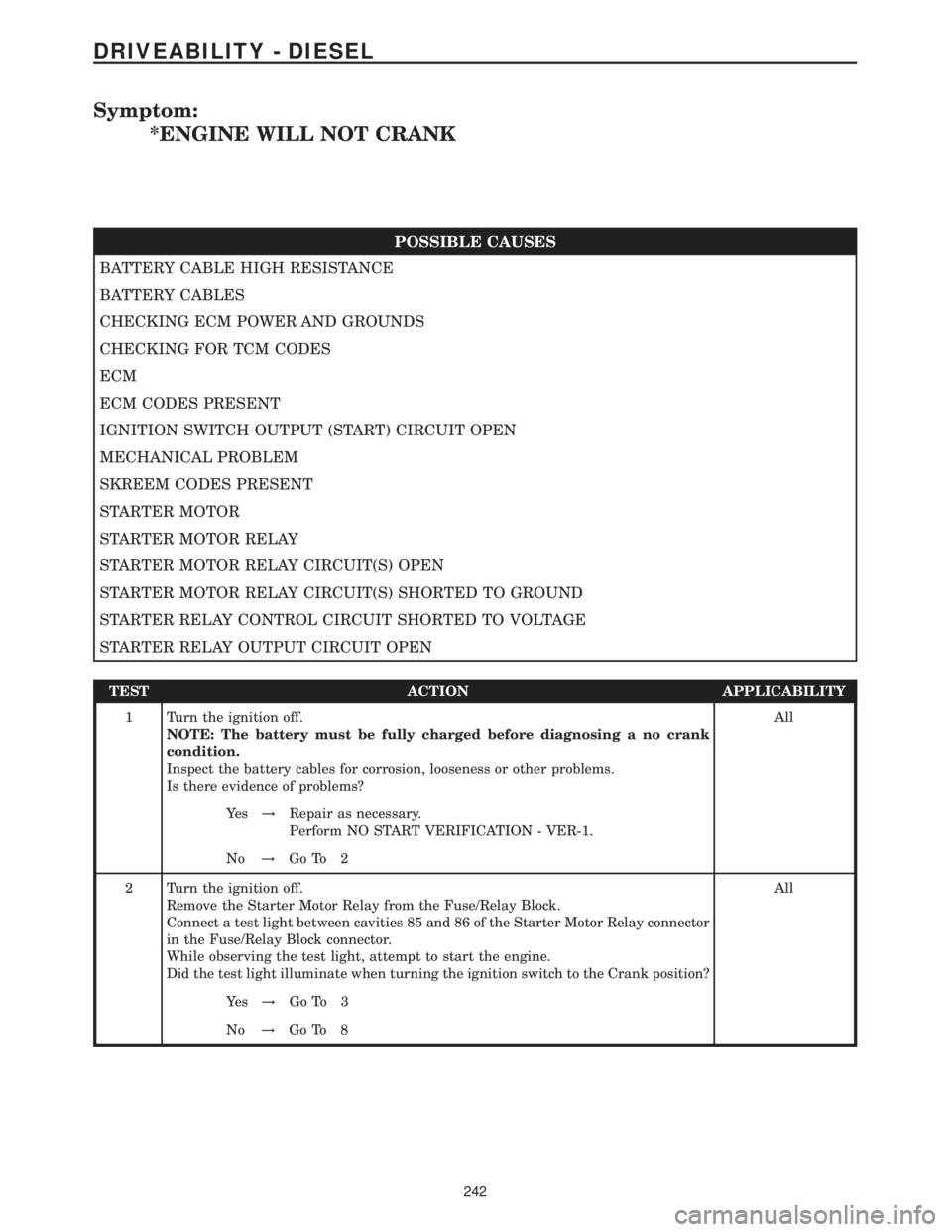
Symptom:
*ENGINE WILL NOT CRANK
POSSIBLE CAUSES
BATTERY CABLE HIGH RESISTANCE
BATTERY CABLES
CHECKING ECM POWER AND GROUNDS
CHECKING FOR TCM CODES
ECM
ECM CODES PRESENT
IGNITION SWITCH OUTPUT (START) CIRCUIT OPEN
MECHANICAL PROBLEM
SKREEM CODES PRESENT
STARTER MOTOR
STARTER MOTOR RELAY
STARTER MOTOR RELAY CIRCUIT(S) OPEN
STARTER MOTOR RELAY CIRCUIT(S) SHORTED TO GROUND
STARTER RELAY CONTROL CIRCUIT SHORTED TO VOLTAGE
STARTER RELAY OUTPUT CIRCUIT OPEN
TEST ACTION APPLICABILITY
1 Turn the ignition off.
NOTE: The battery must be fully charged before diagnosing a no crank
condition.
Inspect the battery cables for corrosion, looseness or other problems.
Is there evidence of problems?All
Ye s!Repair as necessary.
Perform NO START VERIFICATION - VER-1.
No!Go To 2
2 Turn the ignition off.
Remove the Starter Motor Relay from the Fuse/Relay Block.
Connect a test light between cavities 85 and 86 of the Starter Motor Relay connector
in the Fuse/Relay Block connector.
While observing the test light, attempt to start the engine.
Did the test light illuminate when turning the ignition switch to the Crank position?All
Ye s!Go To 3
No!Go To 8
242
DRIVEABILITY - DIESEL
Page 666 of 2305
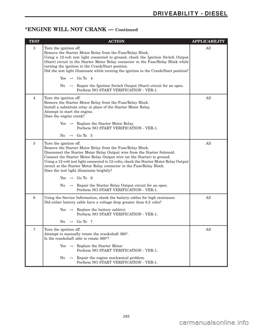
TEST ACTION APPLICABILITY
3 Turn the ignition off.
Remove the Starter Motor Relay from the Fuse/Relay Block.
Using a 12-volt test light connected to ground, check the Ignition Switch Output
(Start) circuit in the Starter Motor Relay connector in the Fuse/Relay Block while
turning the ignition to the Crank/Start position.
Did the test light illuminate while turning the ignition to the Crank/Start position?All
Ye s!Go To 4
No!Repair the Ignition Switch Output (Start) circuit for an open.
Perform NO START VERIFICATION - VER-1.
4 Turn the ignition off.
Remove the Starter Motor Relay from the Fuse/Relay Block.
Install a substitute relay in place of the Starter Motor Relay.
Attempt to start the engine.
Does the engine crank?All
Ye s!Replace the Starter Motor Relay.
Perform NO START VERIFICATION - VER-1.
No!Go To 5
5 Turn the ignition off.
Remove the Starter Motor Relay from the Fuse/Relay Block.
Disconnect the Starter Motor Relay Output wire from the Starter Solenoid.
Connect the Starter Motor Relay Output wire (at the Starter) to ground.
Using a 12-volt test light connected to 12-volts, check the Starter Motor Relay Output
circuit at the Starter Motor Relay connector in the Fuse/Relay Block.
Does the test light illuminate brightly?All
Ye s!Go To 6
No!Repair the Starter Relay Output circuit for an open.
Perform NO START VERIFICATION - VER-1.
6 Using the Service Information, check the battery cables for high resistance.
Did either battery cable have a voltage drop greater than 0.2 volts?All
Ye s!Replace the battery cable(s).
Perform NO START VERIFICATION - VER-1.
No!Go To 7
7 Turn the ignition off.
Attempt to manually rotate the crankshaft 360É.
Is the crankshaft able to rotate 360É?All
Ye s!Replace the Starter Motor.
Perform NO START VERIFICATION - VER-1.
No!Repair the engine mechanical problem.
Perform NO START VERIFICATION - VER-1.
243
DRIVEABILITY - DIESEL
*ENGINE WILL NOT CRANK ÐContinued
Page 723 of 2305
effect panels. If necessary, remove the wheels from
the lifted end of the vehicle and lower the vehicle
closer to the ground, to increase the ground clearance
at the opposite end of the vehicle. Install lug nuts on
wheel attaching studs to retain brake drums.
RAMP ANGLE
If a vehicle with flat-bed towing equipment is used,
the approach ramp angle should not exceed 15
degrees.
TOWING WHEN KEYS ARE NOT AVAILABLE
When the vehicle is locked and keys are not avail-
able, use a flat bed hauler. A Wheel-lift or Sling-type
device can be used provided all the wheels are lifted
off the ground using tow dollies.
MAINTENANCE SCHEDULES
DESCRIPTION
The use of special lubricant additives is not recom-
mended. The use of such additives may affect the
warranty rights. With regard to legal stipulations
concerning emissions control, please note that
engines have to be serviced and adjusted in accor-
dance with special instructions and using special
measuring equipment. Modifications to or interfer-
ence with the emissions control systems are not per-
missible.
MAINTENANCE - WITHOUT ASSYST MAINTE-
NANCE COMPUTER
Maintenance Intervals
²Oil service ±Normal Operationevery 10,000
miles or 16,000 km or 12 months.
²Maintenance service every 30,000 miles or
48,000 km.
Additional work must be carried out at yearly
intervals.
MAINTENANCE - WITH ASSYST MAINTENANCE
COMPUTER
ASSYST provides information on the best possible
timing for maintenance work.
When the next maintenance service is due, this
will be indicated in the multi-function display with
the wrench icon symbol displayed in km/miles or
days.
²One wrench icon showing indicates Oil Service
is necessary.
²Two wrench icons showing indicates Mainte-
nance Service is necessary ± displayed in km/miles or
days.
If the display shows the number of days, a clock
symbol will also appear in the multi-function display.You should have the maintenance performed
within the stated period/distance.
The service indicator will be reset after an oil ser-
vice and/or maintenance service has been performed.
REGULAR CHECK - UPS
To maintain the safe operation of the vehicle, it is
recommended that the following tasks be performed
on a regular basis (i.e. weekly or whenever the vehi-
cle is refueled). Check:
²Engine oil level
²Brake system - fluid level
²Battery - acid level
²Windshield washer system and headlamp clean-
ing system - fluid level
²Mechanical assemblies (e.g. engine, transmis-
sion, etc.) - check for leaks
²Condition of tires and tires pressures
²All exterior lights
SPECIAL MAINTENANCE REQUIREMENTS
If bodies built by manufacturers other than
DaimlerChrysler Corporation are fitted to the vehi-
cle, the maintenance requirements and lubrication
intervals specified by the body manufacturer must be
adhered to, in addition to all standard maintenance
requirements.
Coolant
Corrosion inhibitor/antifreeze concentration in the
coolant should be checked before the onset of winter
(once year in countries with high prevailing temper-
atures).
Replace the coolant every five years or 100,000
miles.
Dust Filter for Heating / Ventilation Replacement
The dust filter and the tailgate interior filter are to
be renewed during routine maintenance service. If
operating conditions are dusty, these filters should be
renewed more frequently.
ENGINE OIL CHANGE AND FILTER REPLACEMENT
At a minimum, change the engine oil and oil filter
once a year ± even if the vehicle mileage per year is
extremely low. For standard oil service schedules
refer to the chapter oil service and maintenance ser-
vice.
Once a Year
Select the viscosity of the engine oil (SAE classes)
according to the outside air temperature.
Only use engine oil approved by DaimlerChrysler
Corporation if following the ASSYST system guide-
lines.
0 - 8 LUBRICATION & MAINTENANCEVA
Page 724 of 2305

SCOPE OF WORK FOR MAINTENANCE SERVICE
Oil Service
²Engine: Oil change and filter replacement
Check fluid levels of the following system, refill as neces-
sary.
²If fluid is lost, trace and eliminate cause - as a
separate order.
²Power-assisted steering
Lubrication work:
²Trailer tow hitch (original equipment)
Maintenance
²ASSYST maintenance computer reset
Function check
²Signalling system, warning and indicator lamps
²Headlamps, exterior lighting
²Windshield wipers, windshield washer system
Check for leaks and damage
²Check for abrasion points and ensure that lines
are correctly routed!
²All lines and hoses, sensor cables
²Rubber boots on front axle drive shafts, rubber
boots on front axle suspension ball joints, shock
absorbers
²Check fluid levels for the following systems, cor-
rect as necessary
NOTE: Should there be a loss of fluid which cannot
be explained by regular use, trace and eliminate the
cause.
²Engine cooling system. Check corrosion inhibi-
tor/antifreeze, refill as necessary.
²Hydraulic brake system
²Battery
²Windshield washer system
Engine
²Fuel filter renewal - Every oil service
²Air cleaner with maintenance indicator:
²Check degree of contamination.
²Air cleaner filter element renewed as necessary.
Chassis and body
²Trailer coupling: Check operation, play and
retaining fixtures
²Secondary rubber springs: Visual check
²Tire pressures: Correct as necessary, including
spare tire
²Check thickness of brake pads
²Brake test
²Check condition of steering mechanism
²Heating/ventilation dust filter renewal
ADDITIONAL MAINTENANCE WORK
Automatic transmission once only at 80,000 miles / 128000
km
²Oil and filter change
During every second maintenance service
²Air cleaner without maintenance indicator:
²Air cleaner filter element renewal
²Check poly-V-belt for wear and signs of damage
During every fourth maintenance service
²Change rear axle fluid
ADDITIONAL MAINTENANCE WORK AFTER YEARS
Every 2 years
²Change brake fluid.
Every 3 years
²Air cleaner filter element renewal (note installa-
tion date)
Every 15 years or 100,000 miles
²Coolant renewal
²Note coolant composition
INTERNATIONAL SYMBOLS
DESCRIPTION
DaimlerChrysler Corporation uses international
symbols to identify engine compartment lubricant
and fluid inspection and fill locations (Fig. 3).
Fig. 3 INTERNATIONAL SYMBOLS
VALUBRICATION & MAINTENANCE 0 - 9
Page 806 of 2305
NOTE: The pressure gauge, connected at the ALB
controller must indicate the outlet pressure which
is assigned on the ALB plate to the rear axle load
determined.
NOTE: If the rear axle load determined is between
two figures indicated on the ALB plate, the outlet
pressure should be determined accordingly.
(8) If the pressure measured differs from the spec-
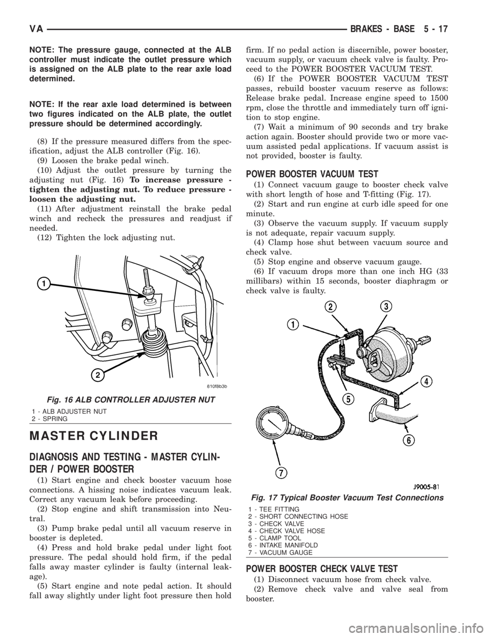
ification, adjust the ALB controller (Fig. 16).
(9) Loosen the brake pedal winch.
(10) Adjust the outlet pressure by turning the
adjusting nut (Fig. 16)To increase pressure -
tighten the adjusting nut. To reduce pressure -
loosen the adjusting nut.
(11) After adjustment reinstall the brake pedal
winch and recheck the pressures and readjust if
needed.
(12) Tighten the lock adjusting nut.
MASTER CYLINDER
DIAGNOSIS AND TESTING - MASTER CYLIN-
DER / POWER BOOSTER
(1) Start engine and check booster vacuum hose
connections. A hissing noise indicates vacuum leak.
Correct any vacuum leak before proceeding.
(2) Stop engine and shift transmission into Neu-
tral.
(3) Pump brake pedal until all vacuum reserve in
booster is depleted.
(4) Press and hold brake pedal under light foot
pressure. The pedal should hold firm, if the pedal
falls away master cylinder is faulty (internal leak-
age).
(5) Start engine and note pedal action. It should
fall away slightly under light foot pressure then holdfirm. If no pedal action is discernible, power booster,
vacuum supply, or vacuum check valve is faulty. Pro-
ceed to the POWER BOOSTER VACUUM TEST.
(6) If the POWER BOOSTER VACUUM TEST
passes, rebuild booster vacuum reserve as follows:
Release brake pedal. Increase engine speed to 1500
rpm, close the throttle and immediately turn off igni-
tion to stop engine.
(7) Wait a minimum of 90 seconds and try brake
action again. Booster should provide two or more vac-
uum assisted pedal applications. If vacuum assist is
not provided, booster is faulty.
POWER BOOSTER VACUUM TEST
(1) Connect vacuum gauge to booster check valve
with short length of hose and T-fitting (Fig. 17).
(2) Start and run engine at curb idle speed for one
minute.
(3) Observe the vacuum supply. If vacuum supply
is not adequate, repair vacuum supply.
(4) Clamp hose shut between vacuum source and
check valve.
(5) Stop engine and observe vacuum gauge.
(6) If vacuum drops more than one inch HG (33
millibars) within 15 seconds, booster diaphragm or
check valve is faulty.
POWER BOOSTER CHECK VALVE TEST
(1) Disconnect vacuum hose from check valve.
(2) Remove check valve and valve seal from
booster.
Fig. 16 ALB CONTROLLER ADJUSTER NUT
1 - ALB ADJUSTER NUT
2 - SPRING
Fig. 17 Typical Booster Vacuum Test Connections
1 - TEE FITTING
2 - SHORT CONNECTING HOSE
3 - CHECK VALVE
4 - CHECK VALVE HOSE
5 - CLAMP TOOL
6 - INTAKE MANIFOLD
7 - VACUUM GAUGE
VABRAKES - BASE 5 - 17