2006 MERCEDES-BENZ SPRINTER check engine light
[x] Cancel search: check engine lightPage 2167 of 2305
The NAG1 will default in the current gear position
if a DTC is detected, then after a key cycle or shift
to park the transmission will go into Limp-in, which
is mechanical 2nd gear. Some DTC's may allow the
transmission to resume normal operation (recover)
if the detected problem goes away. Permanent
limp-in DTC will recover when the key is cycled, but
if the same DTC is detected for three key cycles the
system will not recover and the DTC must be
cleared from the TCM with the DRBIII scan tool.
Once the DRBIIItis in the Transmission portion
of the diagnostic program, it constantly monitors
the TCM to see if the system is in limp-in mode. If
the transmission is in limp-in mode, the DRBIIIt
will flash the red LED.
3.2.1 CONTROLLER MODES OF
OPERATION
Permanent limp-in mode
When the TCM determines there is a non-
recoverable condition present that will not allow
proper transmission operation, it will place the
transmission in permanent limp-in mode. When the
condition occurs the TCM will turn off all solenoids
as well as the solenoid supply output circuit. If this
occurs while the vehicle is moving, the transmission
will remain in the current gear until the ignition is
turned off or shifter is placed in the9P9position.
Once the shifter has been placed in9P9the Trans-
mission will only allow 2nd gear operation. If the
problem occurs while the vehicle is not moving the
transmission will only allow 2nd gear operation.
Temporary limp-in mode
This mode is the same as the permanent limp-in
mode except if the condition is no longer present the
system will resume normal operation. (Recoverable
DTC)
Undervoltage limp-in mode
When the TCM detects that system voltage has
dropped below 8.5 volts it will disable voltage de-
pendant diagnostics and place the transmission in
the temporary limp-in mode. When the TCM senses
that the voltage has risen above 9.0 volts, normal
transmission operation will be resumed.
Hardware Error Mode
When the TCM detects a major internal error the
transmission will be placed in the permanent
limp-in mode and cease all communication over the
CAN bus. Once the TCM has entered this mode
normal transmission operation will not resume un-
til all DTC's are cleared from the TCM.
Loss of Drive
If the TCM detects a situation that has resulted or
may result in engine or transmission failure, the
transmission will be placed in the neutral position.Improper Ratio, Input Sensor Overspeed, or Engine
Overspeed DTC's will cause the loss of drive.
Controlled Limp-in Mode
When a failure condition does not require the TCM
to shut down the solenoid supply, but the failure is
of a degree where the TCM will place the transmis-
sion into a predefined gear, there will be several
shift performance issues. Examples of this are, with
the transmission slipping the controller will at-
tempt to place the transmission into third gear and
maintain third gear for all forward drive conditions.
Another example is some of the CAN bus message
issues if the TCM does not receive required infor-
mation from the Engine Controller, then default
values are used which may result in poor transmis-
sion shift performance.
3.2.2 MIL ILLUMINATION
For failures detected by the Transmission Con-
troller that result in the controller placing the
transmission into a limp-in mode, except for System
Overvoltage and System Undervoltage DTCs, the
MIL will be illuminated. The Transmission Control
Module will inform the ECM over the CAN bus that
a failure has occurred. The ECM will illuminate the
MIL. If the condition is removed and the failure
becomes Stored (Intermittent), the Transmission
controller will stop reporting that the DTC is active
and the ECM will extinguish the MIL.
NOTE: The MIL will light when the problem is
first detected and it will not go off until the
next ignition cycle, after all problem
conditions have been checked for their
presence. This normally takes several
minutes of driving.
3.2.3 SOLENOIDS
1-2/4-5 solenoid -The 1-2/4-5 solenoid is activated
when the TCM determines that the transmission
must shift into or out of 2nd gear or 5th gear. The
solenoid is only activated during the shifting of the
transmission. When the solenoid is activated, hy-
draulic pressure is applied to the proper shift ele-
ments in the transmission to allow the desired shift.
Once the shift is completed, the solenoid is turned
off.
2-3 solenoid -The 2-3 solenoid is activated when
the TCM determines that the transmission must
shift into or out of 3rd gear. The solenoid is only
activated during the shifting of the transmission.
When the solenoid is activated hydraulic pressure
is applied to the proper shift elements in the trans-
mission to allow the desired shift. Once the shift is
completed, the solenoid is turned off.
2
GENERAL INFORMATION
Page 2168 of 2305
3-4 solenoid -The 3-4 solenoid is activated when
the TCM determines that the transmission must
shift into or out of 4th gear. The solenoid is only
activated during the shifting of the transmission.
When the solenoid is activated, hydraulic pressure
is applied to the proper shift elements in the trans-
mission to allow the desired shift. Once the shift is
completed, the solenoid is turned off.
TCC solenoid -The TCC solenoid is activated
when the TCM determines that the Torque con-
verter clutch should be activated. The TCC clutch is
a variable slip torque clutch that allows control of
torque converter slip from 5% to 95.5% of full TCC
engagement. The clutch is controlled by the TCC
solenoid which is pulse width modulated (PWM) to
provide the desired amount of slip.
Shift Pressure Solenoid -The Shift Pressure
Solenoid is activated when the TCM determines
that a transmission shift is required. The solenoid
is PWM controller to allow the proper amount of
hydraulic pressure to the shift elements. The sole-
noid is only activated during the shifting of the
transmission. When the solenoid is activated, hy-
draulic pressure is removed from the proper shift
elements to allow the desired shift. Once the shift is
completed, the solenoid is turned off.
Modulation pressure solenoid -The modulation
pressure is always active. The solenoid is pulse
width modulated (PWM) controlled and is used to
modulate the hydraulic system pressure to the
desired pressure.
3.2.4 TRANSMISSION COMPONENT
DESCRIPTIONS
Shift Assembly
The Shift Lever Selector transmits all selector lever
positions, as well as selected shift ranges to the
TCM over the CAN Bus. At the same time, the
selector lever positions P, R, N, and D are transmit-
ted by a cable to the selector lever shaft in the
transmission.
Brake shift inter-lock
To prevent unauthorized shifting out of the park
position, the Selector lever is locked in the Park
position until the ignition key is turned to the run
position and the brake pedal is pressed. This will
allow the driver to shift out of the park position.
Reverse Lamp Output
The Reverse Light Switch is integrated into the
shifter module and controls the reverse lights.
Reverse Inhibitor
The Shift Lever Assembly constantly monitors ABS
wheel speed to prevents an inadvertent selection of
reverse at speeds above approximately 6.4 Km/h(4MPH). The Reverse inhibitor is part of the Shift
Lever Assembly and is controlled by the Shift Lever
Assembly module.
Trans temp sensor - P/N Switch circuit
The TCM will detect the selector lever in park and
neutral positions. The TCM does this by monitoring
the Transmission temperature sensor signal along
with the shifter position signals. The P/N switch
contact is operated by a cam located in the trans-
mission which, opens a reed contact switch that is
wired in series with the transmission temperature
sensor. When the P/N contact switch is opened in
park and neutral, the TCM senses a high transmis-
sion temperature. Confirming the P/N switch sta-
tus. Note: In park or neutral, the TCM uses engine
temperature (to avoid setting a DTC). The TCM
sends a hardwired signal to the ECM that will allow
the ECM controlled start circuit to engage in P or N
only. The TCM also sends a P/N bus message to the
ECM to confirm the P/N switch status.
The Normal Transmission Temperature Sensor
resistance is between 500.0 and 2500.0 ohms.
The normal voltage limits for the transmis-
sion temperature sensor, are between 0.5 and
3.0 volts.
Input Speed Sensors
The NAG1 transmission has two input speed sen-
sors N2 and N3, both speed sensors are located on
the valve body and report DTC's for the input speed
sensors errors. The speed sensors are Hall Effect
speed sensors that are used by the TCM to calculate
the transmissions input speed. Since the input
speed could not be measured directly, two of the
drive elements are measured. Two input speed
sensors were required because both drive elements
are not active in all gears. The input sensors N2 and
N3 will report the same input speed in gears 2nd,
3rd or 4th. If the N2 and N3 input speed signals are
not the same in these gears then there is an issue
with the transmission and the DTC Input Sensors
Mismatch will be set.
The N3 input speed is not reported in1st and 5th
gears. The N2 sensor is not reported in Reverse.
The Input Speed Sensor Overspeed is a rationality
check that is intended to indicate a major transmis-
sion failure and will cause a loss of drive (place the
transmission in Neutral)
Output Speed Sensor (ABS signal)
The NAG1 transmission does not have an output
shaft speed sensor. The TCM uses the ABS (An-
tilock Brake System) Wheel Speed sensor informa-
tion, it receives over the CAN bus, to calculate the
transmissions output shaft speed. The TCM moni-
tors the ABS system for functionality and reports
ABS speed sensor and communication DTCs, which
will affect proper transmission operation.
3
GENERAL INFORMATION
Page 2170 of 2305
Emergency running function
If DTCs occur, safe-driving conditions must be re-
tained but full functionality of the transmission will
be limited to avoid damaging the automatic trans-
mission. In the event of certain DTCs the TCM
switches to emergency running. The TCM will store
the appropriate DTC codes and solenoids will be
de-energized (turned off)
The transmission effects will be:
²The last gear shifted remains in that position
²The modulating pressure and shift pressure in-
crease to maximum value
²The torque converter clutch is disengaged
(turned off)
Shifting manually after a DTC detection
NOTE: The vehicle can still be shifted
manually to 2nd or reverse gear.
To accomplish these shifts you must
Stop the vehicle
Turn the ignition off
Start the engine
Place the selector lever into D for 2nd gear
Place the selector lever into R for reverse gear
The emergency running function is retained until
the DTC is eliminated or the stored DTC code is
erased.
Stored (Intermittent) DTCs can be reset by cy-
cling the ignition switch
3.3.3 TROUBLE CODE ERASURE
Diagnostic Trouble Codes can be erased in two
ways. The first is to erase the DTC with the DRBIII
or scan tool. The second is if the DTC is no longer
present, the DTC is reset by the TCM (after an
ignition cycle), which will place the DTC in an
intermittent status (Stored DTC).
When there are no diagnostic trouble codes
stored in memory, the DRBIIItwill display
(NO DTC's DETECTED(
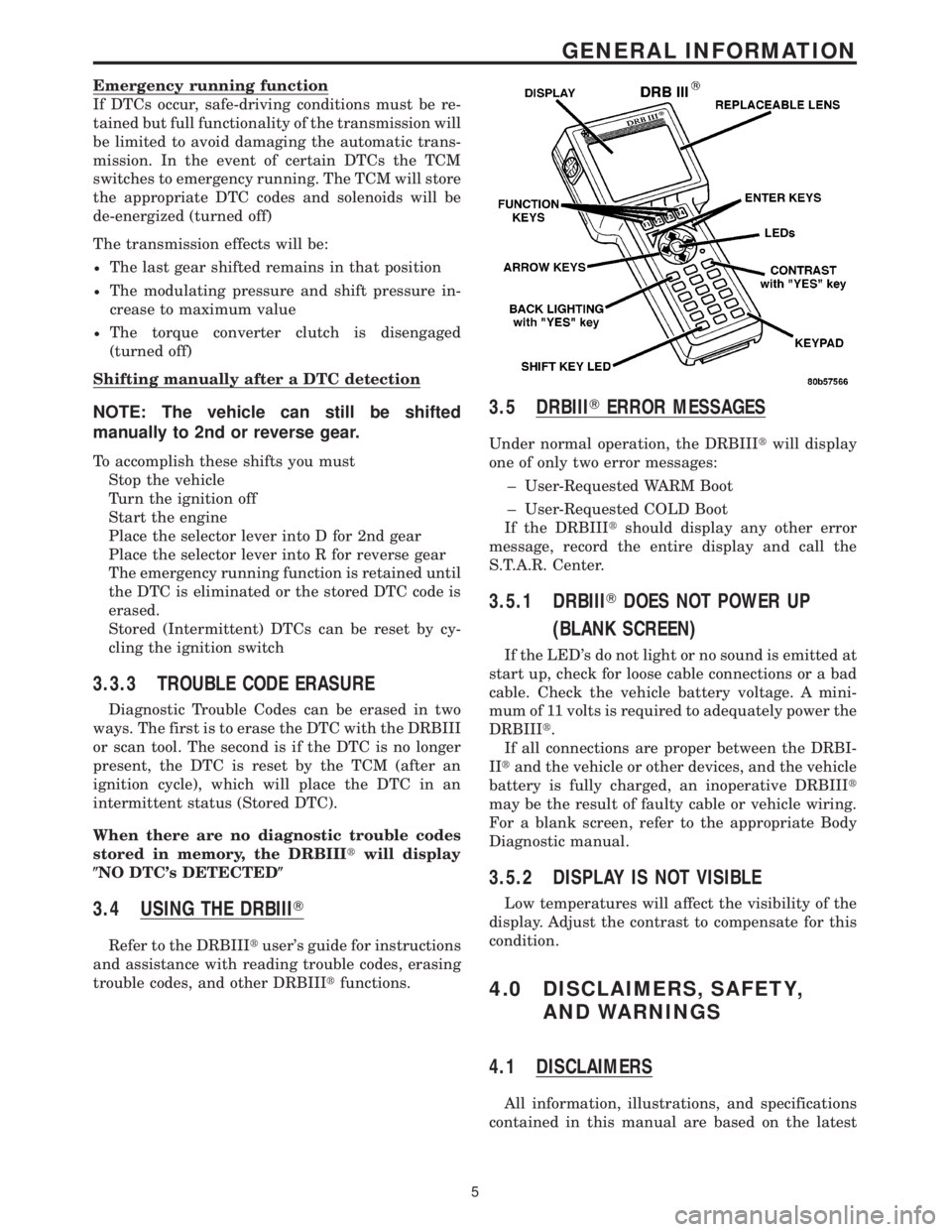
3.4 USING THE DRBIIIT
Refer to the DRBIIItuser's guide for instructions
and assistance with reading trouble codes, erasing
trouble codes, and other DRBIIItfunctions.
3.5 DRBIIITERROR MESSAGES
Under normal operation, the DRBIIItwill display
one of only two error messages:
± User-Requested WARM Boot
± User-Requested COLD Boot
If the DRBIIItshould display any other error
message, record the entire display and call the
S.T.A.R. Center.
3.5.1 DRBIIITDOES NOT POWER UP
(BLANK SCREEN)
If the LED's do not light or no sound is emitted at
start up, check for loose cable connections or a bad
cable. Check the vehicle battery voltage. A mini-
mum of 11 volts is required to adequately power the
DRBIIIt.
If all connections are proper between the DRBI-
IItand the vehicle or other devices, and the vehicle
battery is fully charged, an inoperative DRBIIIt
may be the result of faulty cable or vehicle wiring.
For a blank screen, refer to the appropriate Body
Diagnostic manual.
3.5.2 DISPLAY IS NOT VISIBLE
Low temperatures will affect the visibility of the
display. Adjust the contrast to compensate for this
condition.
4.0 DISCLAIMERS, SAFETY,
AND WARNINGS
4.1 DISCLAIMERS
All information, illustrations, and specifications
contained in this manual are based on the latest
5
GENERAL INFORMATION
Page 2180 of 2305
Symptom:
BACKUP LAMP CKT SHORT TO VOLTAGE OR OPEN
POSSIBLE CAUSES
BACKUP LAMP CIRCUIT OPEN
BACKUP LAMP CIRCUIT SHORT TO VOLTAGE
SHIFT LEVER ASSEMBLY
TEST ACTION APPLICABILITY
1 Start the engine.
While back probing, measure the voltage of the Backup Lamp circuit.
Is the voltage above 0.5 volts?All
Ye s!Go To 2
No!Go To 3
2 Turn the ignition off to the lock position.
Disconnect the Shift Lever Assembly harness connector.
Start the engine.
Measure the voltage of the Backup Lamp circuit in the Shift Lever Assembly harness
connector.
Is the voltage above 0.5 volts?All
Ye s!Repair the Backup Lamp circuit for a short to voltage.
No!Replace the Shift Lever Assembly per the Service Information.
3 Turn the ignition off to the lock position.
Disconnect the Shift Lever Assembly harness connector.
Remove the Backup Lamp bulb(s).
Connect a jumper wire between Shift Lever Assembly circuit and B(+).
Using a 12-volt test light connected to 12-volts, check the Backup Lamp circuit in the
Backup Lamp socket(s).
NOTE: The test light must illuminate brightly. Compare the brightness to
that of a direct connection to the battery.
Does the test light illuminate brightly?All
Ye s!Replace the Shift Lever Assembly per the Service Information.
No!Repair the Backup Lamp circuit for an open.
15
SHIFT LEVER ASSEMBLY
Page 2181 of 2305
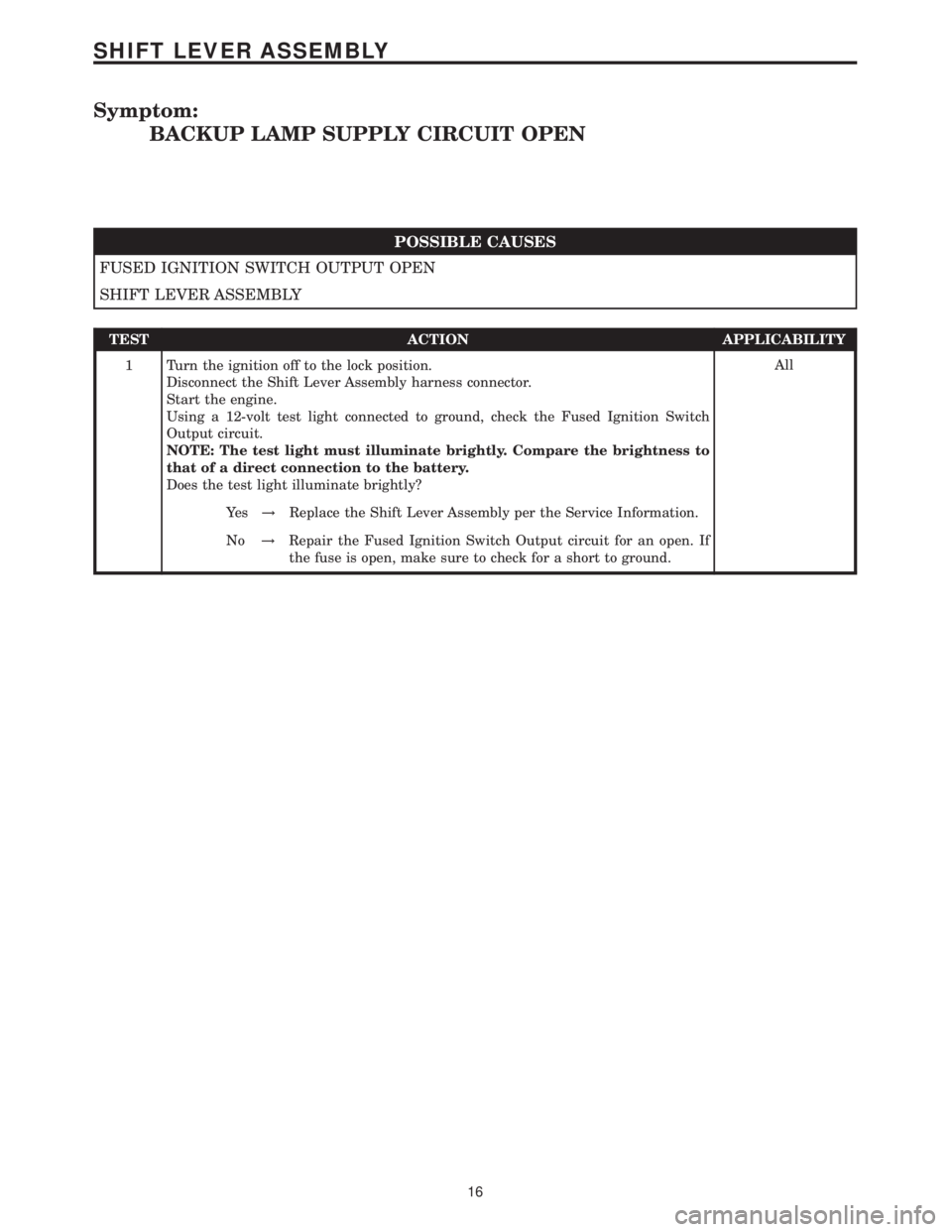
Symptom:
BACKUP LAMP SUPPLY CIRCUIT OPEN
POSSIBLE CAUSES
FUSED IGNITION SWITCH OUTPUT OPEN
SHIFT LEVER ASSEMBLY
TEST ACTION APPLICABILITY
1 Turn the ignition off to the lock position.
Disconnect the Shift Lever Assembly harness connector.
Start the engine.
Using a 12-volt test light connected to ground, check the Fused Ignition Switch
Output circuit.
NOTE: The test light must illuminate brightly. Compare the brightness to
that of a direct connection to the battery.
Does the test light illuminate brightly?All
Ye s!Replace the Shift Lever Assembly per the Service Information.
No!Repair the Fused Ignition Switch Output circuit for an open. If
the fuse is open, make sure to check for a short to ground.
16
SHIFT LEVER ASSEMBLY
Page 2198 of 2305
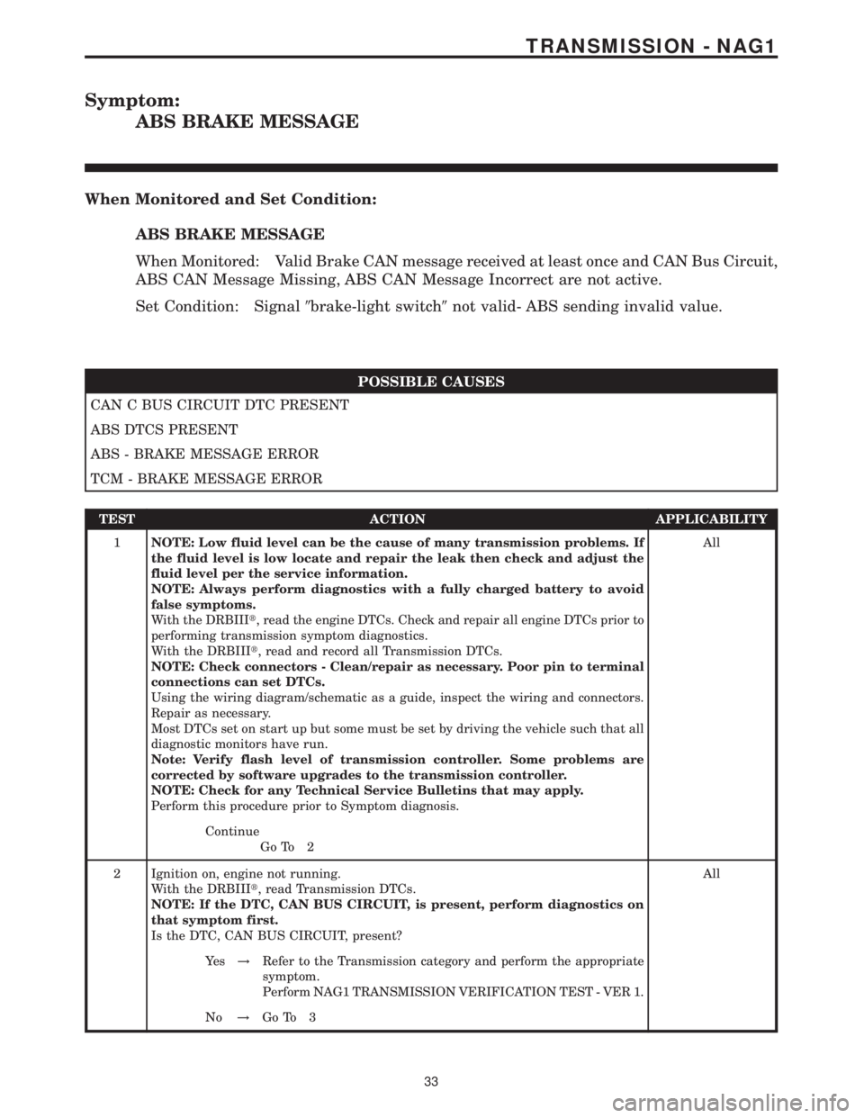
Symptom:
ABS BRAKE MESSAGE
When Monitored and Set Condition:
ABS BRAKE MESSAGE
When Monitored: Valid Brake CAN message received at least once and CAN Bus Circuit,
ABS CAN Message Missing, ABS CAN Message Incorrect are not active.
Set Condition: Signal9brake-light switch9not valid- ABS sending invalid value.
POSSIBLE CAUSES
CAN C BUS CIRCUIT DTC PRESENT
ABS DTCS PRESENT
ABS - BRAKE MESSAGE ERROR
TCM - BRAKE MESSAGE ERROR
TEST ACTION APPLICABILITY
1NOTE: Low fluid level can be the cause of many transmission problems. If
the fluid level is low locate and repair the leak then check and adjust the
fluid level per the service information.
NOTE: Always perform diagnostics with a fully charged battery to avoid
false symptoms.
With the DRBIIIt, read the engine DTCs. Check and repair all engine DTCs prior to
performing transmission symptom diagnostics.
With the DRBIIIt, read and record all Transmission DTCs.
NOTE: Check connectors - Clean/repair as necessary. Poor pin to terminal
connections can set DTCs.
Using the wiring diagram/schematic as a guide, inspect the wiring and connectors.
Repair as necessary.
Most DTCs set on start up but some must be set by driving the vehicle such that all
diagnostic monitors have run.
Note: Verify flash level of transmission controller. Some problems are
corrected by software upgrades to the transmission controller.
NOTE: Check for any Technical Service Bulletins that may apply.
Perform this procedure prior to Symptom diagnosis.All
Continue
Go To 2
2 Ignition on, engine not running.
With the DRBIIIt, read Transmission DTCs.
NOTE: If the DTC, CAN BUS CIRCUIT, is present, perform diagnostics on
that symptom first.
Is the DTC, CAN BUS CIRCUIT, present?All
Ye s!Refer to the Transmission category and perform the appropriate
symptom.
Perform NAG1 TRANSMISSION VERIFICATION TEST - VER 1.
No!Go To 3
33
TRANSMISSION - NAG1