2006 MERCEDES-BENZ SPRINTER check engine light
[x] Cancel search: check engine lightPage 1662 of 2305
OPERATION
Intake air is drawn through the air cleaner and
into the turbocharger compressor housing. Pressur-
ized air from the turbocharger then flows forward
through the charge air cooler located in front of the
radiator. From the charge air cooler the air flows
back into the intake manifold.
DIAGNOSIS AND TESTING - CHARGE AIR
COOLER SYSTEM - LEAKS
NOTE: Slight engine oil pooling in the charge air
inlet hose IS NOT premature turbocharger failure.
Slight pooling is the normal result of the breather
system. Test the air breather tube for normal oper-
ation by referring to the appropriate diagnostic
manual.
Low turbocharger boost pressure and low engine
performance can be caused by leaks in the charge air
cooler or it's plumbing. The following procedure out-
lines how to check for leaks in the charge air cooler
system.
(1) Loosen clamp and remove turbocharger to air
inlet duct rubber sleeve from turbocharger.
(2) Insert Special Tool 8442 Adapter into the rub-
ber sleeve. Tighten existing clamp to 8 N´m (72
in.lbs.).
CAUTION: Do not apply more than 138 kpa (20 psi)
air pressure to the charge air cooler system, sever
damage to the charge air cooler system may occur.
(3) Connect regulated air supply to air fitting on
Special Tool 8442 Adapter. Set air pressure to a Max-
imum of 138 kpa (20 psi).
(4) Using soapy water check the air inlet ducts,
rubber sleeves, charge air cooler and intake manifold
for leaks.
REMOVAL
(1) Remove front bumper.
(2) Remove headlamp assemblies.
(3) Remove front cross member together with front
grille.
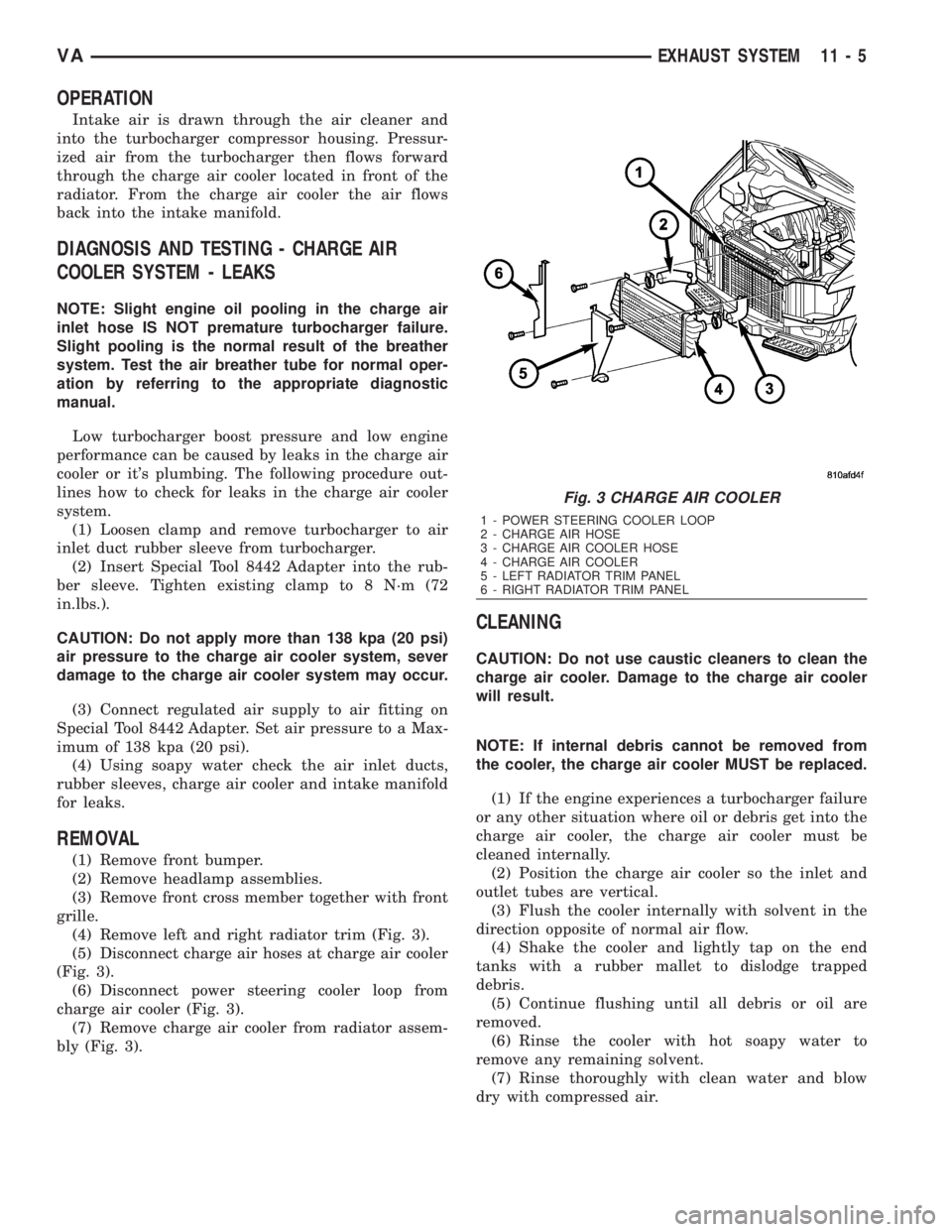
(4) Remove left and right radiator trim (Fig. 3).
(5) Disconnect charge air hoses at charge air cooler
(Fig. 3).
(6) Disconnect power steering cooler loop from
charge air cooler (Fig. 3).
(7) Remove charge air cooler from radiator assem-
bly (Fig. 3).
CLEANING
CAUTION: Do not use caustic cleaners to clean the
charge air cooler. Damage to the charge air cooler
will result.
NOTE: If internal debris cannot be removed from
the cooler, the charge air cooler MUST be replaced.
(1) If the engine experiences a turbocharger failure
or any other situation where oil or debris get into the
charge air cooler, the charge air cooler must be
cleaned internally.
(2) Position the charge air cooler so the inlet and
outlet tubes are vertical.
(3) Flush the cooler internally with solvent in the
direction opposite of normal air flow.
(4) Shake the cooler and lightly tap on the end
tanks with a rubber mallet to dislodge trapped
debris.
(5) Continue flushing until all debris or oil are
removed.
(6) Rinse the cooler with hot soapy water to
remove any remaining solvent.
(7) Rinse thoroughly with clean water and blow
dry with compressed air.
Fig. 3 CHARGE AIR COOLER
1 - POWER STEERING COOLER LOOP
2 - CHARGE AIR HOSE
3 - CHARGE AIR COOLER HOSE
4 - CHARGE AIR COOLER
5 - LEFT RADIATOR TRIM PANEL
6 - RIGHT RADIATOR TRIM PANEL
VAEXHAUST SYSTEM 11 - 5
Page 1699 of 2305
CAUTION: DO NOT crimp or bend fuel line. Inspect
sealing cone at line; replace line if compression
exists.
NOTE: Care must be taken not to cross the fuel
return and supply lines during installation.
(2) Attach fuel flow supply and return lines,
recrimping clamps using special tool #9539 (Fig. 9).
CAUTION: NEVER slacken the thread connection.
Use a wrench to counterhold at threaded connec-
tion when slackening and tightening torque in order
to avoid also slackening the threaded connection
the next time.
CAUTION: DO NOT crimp or bend fuel line. Inspect
sealing cone at line; replace line if compression
exists.
(3) Attach high pressure fuel line to pump.
Tighten to 22N´m (194 lbs.in.) (Fig. 9).
(4) Install the viscous fan.
(5) Connect negative battery cable.
(6) Start engine, allow to run, turn engine off and
inspect for leaks (Refer to 14 - FUEL SYSTEM -
WARNING), (Refer to 14 - FUEL SYSTEM - DIAG-
NOSIS AND TESTING).
FUEL PUMP MODULE
DESCRIPTION
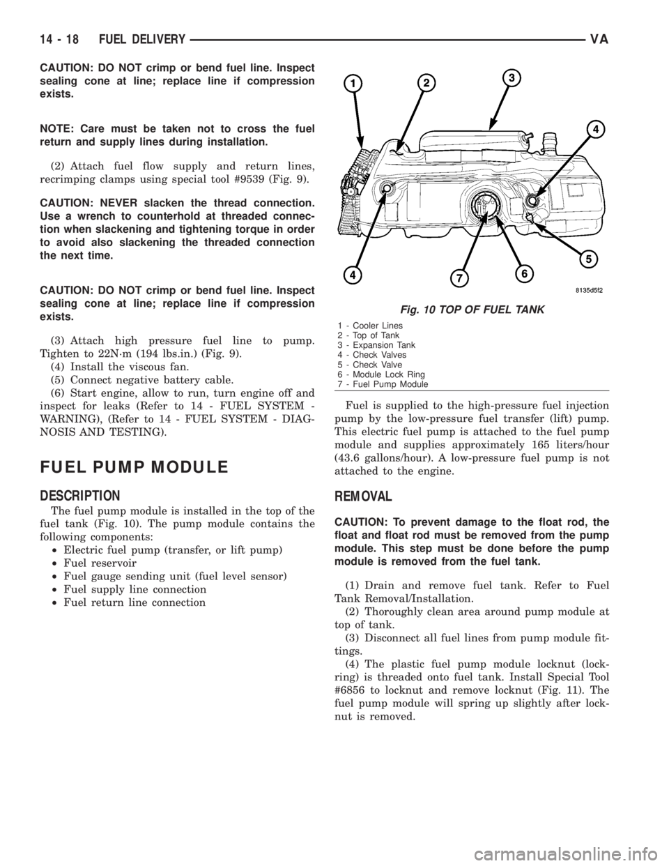
The fuel pump module is installed in the top of the
fuel tank (Fig. 10). The pump module contains the
following components:
²Electric fuel pump (transfer, or lift pump)
²Fuel reservoir
²Fuel gauge sending unit (fuel level sensor)
²Fuel supply line connection
²Fuel return line connectionFuel is supplied to the high-pressure fuel injection
pump by the low-pressure fuel transfer (lift) pump.
This electric fuel pump is attached to the fuel pump
module and supplies approximately 165 liters/hour
(43.6 gallons/hour). A low-pressure fuel pump is not
attached to the engine.
REMOVAL
CAUTION: To prevent damage to the float rod, the
float and float rod must be removed from the pump
module. This step must be done before the pump
module is removed from the fuel tank.
(1) Drain and remove fuel tank. Refer to Fuel
Tank Removal/Installation.
(2) Thoroughly clean area around pump module at
top of tank.
(3) Disconnect all fuel lines from pump module fit-
tings.
(4) The plastic fuel pump module locknut (lock-
ring) is threaded onto fuel tank. Install Special Tool
#6856 to locknut and remove locknut (Fig. 11). The
fuel pump module will spring up slightly after lock-
nut is removed.
Fig. 10 TOP OF FUEL TANK
1 - Cooler Lines
2-TopofTank
3 - Expansion Tank
4 - Check Valves
5 - Check Valve
6 - Module Lock Ring
7 - Fuel Pump Module
14 - 18 FUEL DELIVERYVA
Page 1742 of 2305
SPECIFICATIONS - TORQUE CHART
TORQUE SPECIFICATIONS
DESCRIPTION N´m Ft. Lbs. In. Lbs.
Power Steering Pump To
Timing Case Cover/Sup-
port21 15 185
High Pressure Flexible
Hose To Power Steering
Pump38 28 336
Power Steering Pulley To
Pump30 22 265
FLUID
STANDARD PROCEDURE
POWER STEERING PUMP FILL AND BLEED
PROCEDURE
(1) Remove the cap from the fluid reservoir.
Check cap seal for damage and replace if
needed.
(2) Fill the power steering pump with approved
fluid (Refer to LUBRICATION & MAINTENANCE/
FLUID TYPES - DESCRIPTION).Do not fill fluid
beyond the MAX mark.
(3) Raise the vehicles front wheels off the ground.
(4) With the engine off turn the steering wheel
from right to left.Perform this step until all the
bubble formations can no longer be seen in the
power steering reservoir.
(5) Start the engine and turn the steering wheel
with the engine at idle speed then shut the engine off
and check for correct oil level and no bubble in the
system.
(6) Reinstall power steering cap tightly.
(7) Test the system for leaks and proper operation.
FLUID COOLER TUBE
REMOVAL
(1) Siphon as much power steering fluid as possi-
ble out of the reservoir.
(2) Remove the grille (Refer to 23 - BODY/EXTE-
RIOR/GRILLE - REMOVAL).
(3) Remove the left headlight assembly.
(4) Disconnect the return lines from the cooler
tube.
(5) Remove the radiator clips (2).
(6) Remove the heat shield bolt for the turbo at
the core support.
(7) Remove the right headlight assembly.(8) Remove the core support bolts (4) and discon-
nect the hood latch cable.
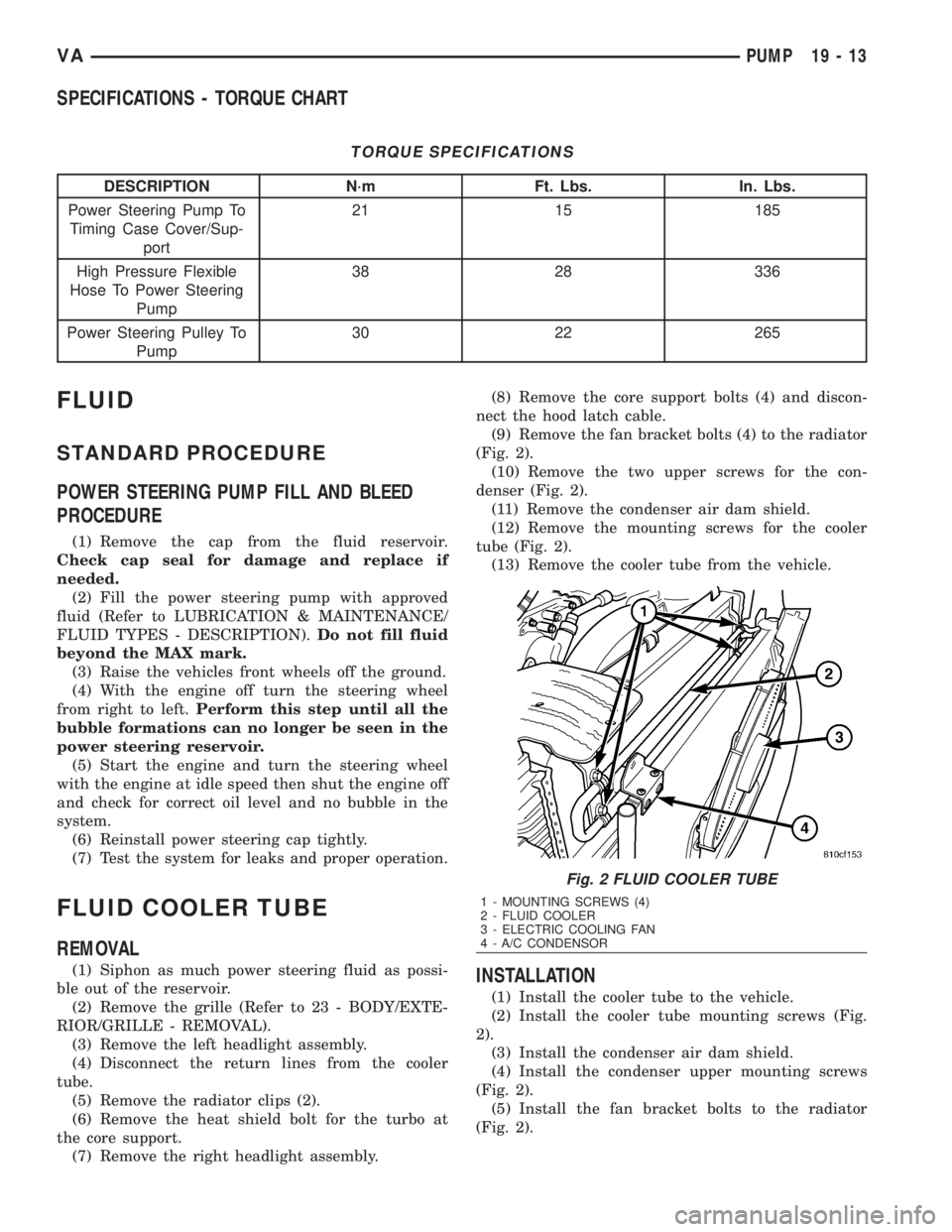
(9) Remove the fan bracket bolts (4) to the radiator
(Fig. 2).
(10) Remove the two upper screws for the con-
denser (Fig. 2).
(11) Remove the condenser air dam shield.
(12) Remove the mounting screws for the cooler
tube (Fig. 2).
(13) Remove the cooler tube from the vehicle.INSTALLATION
(1) Install the cooler tube to the vehicle.
(2) Install the cooler tube mounting screws (Fig.
2).
(3) Install the condenser air dam shield.
(4) Install the condenser upper mounting screws
(Fig. 2).
(5) Install the fan bracket bolts to the radiator
(Fig. 2).
Fig. 2 FLUID COOLER TUBE
1 - MOUNTING SCREWS (4)
2 - FLUID COOLER
3 - ELECTRIC COOLING FAN
4 - A/C CONDENSOR
VAPUMP 19 - 13
Page 1789 of 2305
(16) Disconnect ground strap and tie back to one
side.
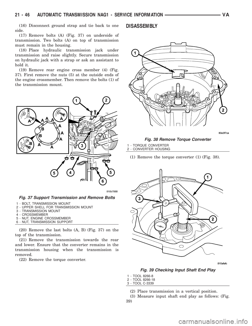
(17) Remove bolts (A) (Fig. 37) on underside of
transmission. Two bolts (A) on top of transmission
must remain in the housing.
(18) Place hydraulic transmission jack under
transmission and raise slightly. Secure transmission
on hydraulic jack with a strap or ask an assistant to
hold it.
(19) Remove rear engine cross member (4) (Fig.
37). First remove the nuts (5) at the outside ends of
the engine crossmember. Then remove the bolts (1) of
the transmission mount.
(20) Remove the last bolts (A, B) (Fig. 37) on the
top of the transmission.
(21) Remove the transmission towards the rear
and lower. Ensure that the converter remains in the
transmission housing when the transmission is
removed.
(22) Remove the torque converter.DISASSEMBLY
(1) Remove the torque converter (1) (Fig. 38).
(2) Place transmission in a vertical position.
(3) Measure input shaft end play as follows: (Fig.
39)
Fig. 37 Support Transmission and Remove Bolts
1 - BOLT, TRANSMISSION MOUNT
2 - UPPER SHELL FOR TRANSMISSION MOUNT
3 - TRANSMISSION MOUNT
4 - CROSSMEMBER
5 - NUT, ENGINE CROSSMEMBER
6 - NUT, TRANSMISSION SUPPORT
Fig. 38 Remove Torque Converter
1 - TORQUE CONVERTER
2 - CONVERTER HOUSING
Fig. 39 Checking Input Shaft End Play
1 - TOOL 8266-8
2 - TOOL 8266-18
3 - TOOL C-3339
21 - 46 AUTOMATIC TRANSMISSION NAG1 - SERVICE INFORMATIONVA
Page 1911 of 2305
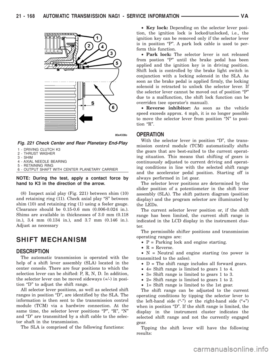
NOTE: During the test, apply a contact force by
hand to K3 in the direction of the arrow.
(8) Inspect axial play (Fig. 221) between shim (10)
and retaining ring (11). Check axial play ªSº between
shim (10) and retaining ring (1) using a feeler gauge.
Clearance should be 0.15-0.6 mm (0.006-0.024 in.).
Shims are available in thicknesses of 3.0 mm (0.118
in.), 3.4 mm (0.134 in.), and 3.7 mm (0.146 in.).
Adjust as necessary
SHIFT MECHANISM
DESCRIPTION
The automatic transmission is operated with the
help of a shift lever assembly (SLA) located in the
center console. There are four positions to which the
selection lever can be shifted: P, R, N, D. In addition,
the selector lever can be moved sideways (+/-) in posi-
tion ªDº to adjust the shift range.
All selector lever positions, as well as selected shift
ranges in position ªDº, are identified by the SLA. The
information is then sent to the transmission control
module (TCM) via a hardwire connection. At the
same time, the selector lever positions ªPº, ªRº, ªNº
and ªDº are transmitted by a shift cable to the selec-
tor shaft in the transmission.
The SLA is comprised of the following functions:²Key lock:Depending on the selector lever posi-
tion, the ignition lock is locked/unlocked, i.e., the
ignition key can be removed only if the selector lever
is in position ªPº. A park lock cable is used to per-
form this function.
²Park lock:The selector lever is not released
from postion ªPº until the brake pedal has been
applied and the ignition key is in driving position.
Shift lock is controlled by the brake light switch in
conjunction with a locking solenoid in the SLA. As
soon as the brake pedal is applied firmly, the locking
solenoid is retracted to unlock the selector lever. If
the selector lever cannot be moved out of position ªPº
due to a malfunction, the shift lock function can be
overriden (see operator's manual).
²Reverse inhibitor:As soon as the vehicle
speed exceeds approx. 4 mph, it is no longer possible
to move the selector lever from position ªNº to posi-
tion ªRº.
OPERATION
With the selector lever in position ªDº, the trans-
mission control module (TCM) automatically shifts
the gears that are best-suited to the current operat-
ing situation. This means that shifting of gears is
continuously adjusted to current driving and operat-
ing conditions in line with the selected shift range
and the accelerator pedal position. Starting off is
always performed in 1st gear.
The selector lever positions are determined by the
slider position of a potentiometer in the shift lever
assembly (SLA). The shift pattern diagram (position
display) and the program selector are illuminated by
the LEDs.
The current selector lever position or, if the shift
range has been limited, the current shift range is
indicated in the LCD display in the instrument clus-
ter.
The permissible shifter positions and transmission
operating ranges are:
²P = Parking lock and engine starting.
²R = Reverse.
²N = Neutral and engine starting (no power is
transmitted to the axles).
²D = The shift range includes all forward gears.
²4= Shift range is limited to gears 1 to 4.
²3= Shift range is limited to gears 1 to 3.
²2= Shift range is limited to gears 1 to 2.
²1= Shift range is limited to the 1st gear.
The shift range can be adjusted to the current
operating conditions by tipping the selector lever to
the left-hand side (ª-º) or the right-hand side (ª+º)
when in position ªDº. If the shift range is limited, the
display in the instrument cluster indicates the
selected shift range and not the currently engaged
gear.
Tipping the shift lever will have the following
results:Fig. 221 Check Center and Rear Planetary End-Play
1 - DRIVING CLUTCH K3
2 - THRUST WASHER
3 - SHIM
4 - AXIAL NEEDLE BEARING
5 - RETAINING RING
6 - OUTPUT SHAFT WITH CENTER PLANETARY CARRIER
21 - 168 AUTOMATIC TRANSMISSION NAG1 - SERVICE INFORMATIONVA
Page 2042 of 2305
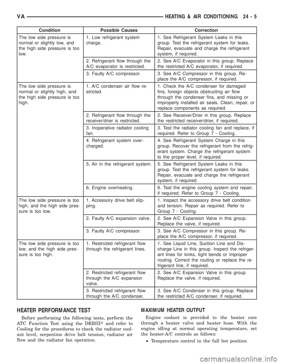
Condition Possible Causes Correction
The low side pressure is
normal or slightly low, and
the high side pressure is too
low.1. Low refrigerant system
charge.1. See Refrigerant System Leaks in this
group. Test the refrigerant system for leaks.
Repair, evacuate and charge the refrigerant
system, if required.
2. Refrigerant flow through the
A/C evaporator is restricted.2. See A/C Evaporator in this group. Replace
the restricted A/C evaporator, if required.
3. Faulty A/C compressor. 3. See A/C Compressor in this group. Re-
place the A/C compressor, if required.
The low side pressure is
normal or slightly high, and
the high side pressure is too
high.1. A/C condenser air flow re-
stricted.1. Check the A/C condenser for damaged
fins, foreign objects obstructing air flow
through the condenser fins, and missing or
improperly installed air seals. Clean, repair, or
replace components as required.
2. Refrigerant flow through the
receiver/drier is restricted.2. See Receiver/Drier in this group. Replace
the restricted receiver/drier, if required.
3. Inoperative radiator cooling
fan.3. Test the radiator cooling fan and replace, if
required. Refer to Group 7 - Cooling.
4. Refrigerant system over-
charged.4. See Refrigerant System Charge in this
group. Recover the refrigerant from the refrig-
erant system. Charge the refrigerant system
to the proper level, if required.
5. Air in the refrigerant system. 5. See Refrigerant System Leaks in this
group. Test the refrigerant system for leaks.
Repair, evacuate and charge the refrigerant
system, if required.
6. Engine overheating. 6. Test the engine cooling system and repair,
if required. Refer to Group 7 - Cooling.
The low side pressure is too
high, and the high side pres-
sure is too low.1. Accessory drive belt slip-
ping.1. Inspect the accessory drive belt condition
and tension. Repair as required. Refer to
Group 7 - Cooling.
2. Faulty A/C expansion valve. 2. See A/C Expansion Valve in this group.
Replace the valve, if required.
3. Faulty A/C compressor. 3. See A/C Compressor in this group. Re-
place the A/C compressor, if required.
The low side pressure is too
low, and the high side pres-
sure is too high.1. Restricted refrigerant flow
through the refrigerant lines.1. See Liquid Line, Suction Line and Dis-
charge Line in this group. Inspect the refriger-
ant lines for kinks, tight bends or improper
routing. Correct the routing or replace the re-
frigerant line, if required.
2. Restricted refrigerant flow
through the A/C expansion
valve.2. See A/C Expansion Valve in this group.
Replace the valve, if required.
3. Restricted refrigerant flow
through the A/C condenser.3. See A/C Condenser in this group. Replace
the restricted A/C condenser, if required.
HEATER PERFORMANCE TEST
Before performing the following tests, perform the
ATC Function Test using the DRBIIItand refer to
Cooling for the procedures to check the radiator cool-
ant level, serpentine drive belt tension, radiator air
flow and the radiator fan operation.
MAXIMUM HEATER OUTPUT
Engine coolant is provided to the heater core
through a heater valve and heater hose. With the
engine idling at normal operating temperature, set
the heater-A/C controls as follows:
²Temperature control in the full hot position
VAHEATING & AIR CONDITIONING 24 - 5
Page 2043 of 2305
²Mode control in the floor heat position
²Blower motor control in the highest speed posi-
tion
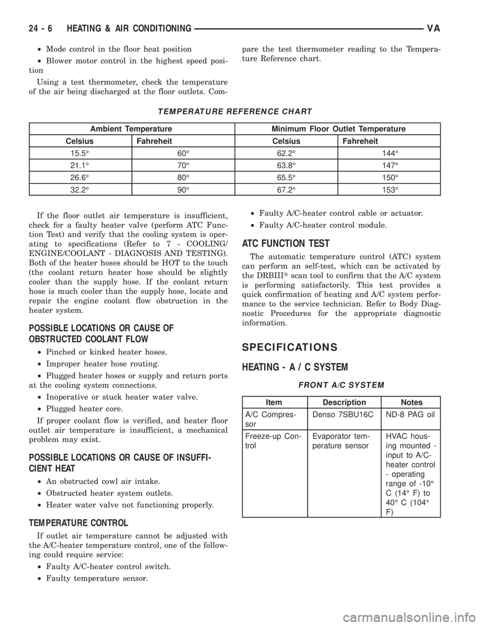
Using a test thermometer, check the temperature
of the air being discharged at the floor outlets. Com-pare the test thermometer reading to the Tempera-
ture Reference chart.
TEMPERATURE REFERENCE CHART
Ambient Temperature Minimum Floor Outlet Temperature
Celsius Fahreheit Celsius Fahreheit
15.5É 60É 62.2É 144É
21.1É 70É 63.8É 147É
26.6É 80É 65.5É 150É
32.2É 90É 67.2É 153É
If the floor outlet air temperature is insufficient,
check for a faulty heater valve (perform ATC Func-
tion Test) and verify that the cooling system is oper-
ating to specifications (Refer to 7 - COOLING/
ENGINE/COOLANT - DIAGNOSIS AND TESTING).
Both of the heater hoses should be HOT to the touch
(the coolant return heater hose should be slightly
cooler than the supply hose. If the coolant return
hose is much cooler than the supply hose, locate and
repair the engine coolant flow obstruction in the
heater system.
POSSIBLE LOCATIONS OR CAUSE OF
OBSTRUCTED COOLANT FLOW
²Pinched or kinked heater hoses.
²Improper heater hose routing.
²Plugged heater hoses or supply and return ports
at the cooling system connections.
²Inoperative or stuck heater water valve.
²Plugged heater core.
If proper coolant flow is verified, and heater floor
outlet air temperature is insufficient, a mechanical
problem may exist.
POSSIBLE LOCATIONS OR CAUSE OF INSUFFI-
CIENT HEAT
²An obstructed cowl air intake.
²Obstructed heater system outlets.
²Heater water valve not functioning properly.
TEMPERATURE CONTROL
If outlet air temperature cannot be adjusted with
the A/C-heater temperature control, one of the follow-
ing could require service:
²Faulty A/C-heater control switch.
²Faulty temperature sensor.²Faulty A/C-heater control cable or actuator.
²Faulty A/C-heater control module.
ATC FUNCTION TEST
The automatic temperature control (ATC) system
can perform an self-test, which can be activated by
the DRBIIItscan tool to confirm that the A/C system
is performing satisfactorily. This test provides a
quick confirmation of heating and A/C system perfor-
mance to the service technician. Refer to Body Diag-
nostic Procedures for the appropriate diagnostic
information.
SPECIFICATIONS
HEATING-A/CSYSTEM
FRONT A/C SYSTEM
Item Description Notes
A/C Compres-
sorDenso 7SBU16C ND-8 PAG oil
Freeze-up Con-
trolEvaporator tem-
perature sensorHVAC hous-
ing mounted -
input to A/C-
heater control
- operating
range of -10É
C (14É F) to
40É C (104É
F)
24 - 6 HEATING & AIR CONDITIONINGVA
Page 2158 of 2305
INDEX
ABS INDICATOR.......................8J-9ACCELERATOR PEDAL POSITION SENSOR. . . 14-32
ACCESSORY SWITCH BEZEL............23-56
ADR INDICATOR.....................8J-10
AIR CLEANER ELEMENT................9-21
AIR CLEANER HOUSING................9-21
AIR FILTER ....................24-45, 24-58
AIR OUTLET TEMPERATURE SENSOR....24-16
AIR OUTLETS.......................24-45
AIRBAG CONTROL MODULE.............8O-8
AIRBAG INDICATOR...................8J-11
ALB CONTROLLER....................5-16
ALB LEVER..........................5-16
AMBIENT TEMPERATURE INDICATOR.....8J-11
AMBIENT TEMPERATURE SENSOR.......24-17
ANTENNA BODY & CABLE..............8A-1
ARMREST..........................23-79
ASH RECEIVER......................23-57
ASH RECEIVER / CIGAR LIGHTER LAMP
UNIT..............................8L-30
ASSIST HANDLE.....................23-71
AUDIO..............................8A-1
AUTOMATIC TRANSMISSION NAG1 -
SERVICE INFORMATION................21-3
A - PILLAR TRIM.....................23-70
A / C CLUTCH RELAY.................24-24
A / C COMPRESSOR CLUTCH COIL.......24-12
A / C COMPRESSOR CLUTCH............24-8
A / C COMPRESSOR..................24-66
A / C CONDENSER COVER.............24-52
A / C CONDENSER FAN RELAY..........24-26
A / C CONDENSER HOUSING...........24-52
A / C CONDENSER....................24-69
A / C CONTROL MODULE..............24-28
A / C DISCHARGE LINE................24-71
A / C EVAPORATOR COVER.............24-55
A / C EVAPORATOR HOUSING...........24-55
A / C EVAPORATOR...................24-72
A / C EXPANSION VALVE...............24-73
A / C HEATER CONTROL...............24-12
A / C HIGH PRESSURE SWITCH.........24-30
A / C LOW PRESSURE SWITCH.........24-32
A / C PRESSURE TRANSDUCER.........24-14
BACKLITE - BULKHEAD TRIM PANEL.....23-84
BACKUP LAMP BULB..................8L-5
BASECOAT / CLEARCOAT FINISH........23-77
BATTERY CABLES....................8F-14
BATTERY HOLDDOWN.................8F-13
BATTERY SYSTEM.....................8F-1
BATTERY TRAY......................8F-16
BATTERY............................8F-6
BEARINGS - DIFFERENTIAL CASE.........3-38
BEARING / SEAL - AXLE HUB............3-28
BEARING / SEAL - AXLE................3-24
BELT TENSIONERS.....................7-5
BLOWER MOTOR RELAY...............24-33
BLOWER MOTOR RESISTOR............24-17
BLOWER MOTOR SWITCH........24-19, 24-35
BLOWER MOTOR...............24-47, 24-58
BODY...............................23-1
BOOST PRESSURE SENSOR............14-33
BRAKE INDICATOR...................8J-12
BRAKE LAMP SWITCH.................8L-6
BRAKE LINES.........................5-8
BRAKE PADS / SHOES...................5-8
BRAKE WEAR INDICATOR..............8J-13
BRAKES - ABS........................5-30
BRAKES - BASE........................5-2
BRAKE / PARK LAMP BULB.............8L-7
BULKHEAD TRIM PANEL...............23-72
BUMPERS...........................13-1
BUSHINGS............................2-3
B - PILLAR TRIM.....................23-71
CABIN HEATER.....................24-104
CABLE TENSIONER....................5-24
CABLE..............................8P-2
CABLES.............................5-24
CAMSHAFT POSITION SENSOR..........14-33
CAMSHAFT(S)........................9-28
CARGO LAMP SWITCH................8L-31
CARGO / DOME LAMP BULB............8L-30
CARGO / DOME LAMP UNIT............8L-31
CARPETS AND FLOOR MATS...........23-72
CATALYTIC CONVERTER
................11-3
CENTER BEARING
......................3-9
CENTER HIGH MOUNTED STOP LAMP BULB. . . 8L-8CENTER HIGH MOUNTED STOP LAMP UN.....8L-8
CENTER ROLLER ARM
................23-36CENTER TRACK......................23-37
CENTRAL TIMER MODULE..............8E-1
CHARGE AIR COOLER AND PLUMBING....11-4
CHARGING INDICATOR................8J-14
CHARGING SYSTEM..................8F-17
CHECK VALVE.......................8R-11
CHECK.......................23-13, 23-23
CHIME / BUZZER......................8B-1
CIGAR LIGHTER OUTLET............8W-97-1
CIRCUIT BREAKER.................8W-97-2
CLEARANCE LAMP BULB...............8L-9
CLEARANCE LAMP UNIT................8L-9
CLOCK.............................8J-14
CLOCKSPRING......................8O-12
CLUSTER BEZEL.....................23-55
COLUMN............................19-4
CONNECTOR.......................Intro.-9
CONNECTOR/GROUND/SPLICE
LOCATION........................8W-91-1
CONTROLLER ANTILOCK BRAKE.........8E-3
COOLANT LEVEL SENSOR...............7-13
COOLANT LOW INDICATOR.............8J-15
COOLANT............................7-9
COOLING.............................7-1
COWL TRIM........................23-73
CRANKCASE VENTILATION BREATHER......25-2
CRANKCASE VENTILATION HEATER.......25-1
CRANKSHAFT OIL SEAL - FRONT.........9-42
CRANKSHAFT OIL SEAL - REAR..........9-41
CRANKSHAFT POSITION SENSOR........14-35
CRANKSHAFT........................9-39
CUP HOLDER........................23-57
CYLINDER HEAD COVER(S).............9-33
CYLINDER HEAD......................9-22
DAYTIME RUNNING LAMP RELAY.......8L-10
DEFROSTER DUCTS..................24-47
DIFFERENTIAL........................3-31
DIODE............................Intro.-9
DISC BRAKE CALIPER ADAPTER.........5-14
DISC BRAKE CALIPERS.................5-11
DOME LAMP / INTRUSION SENSOR
BULB..............................8L-33
DOME LAMP / INTRUSION SENSOR......8L-33
DOME / READING LAMP BULB..........8L-32
DOME / READING LAMP UNIT..........8L-32
DOOR GLASS............23-15, 23-30, 23-46
DOOR JAMB SWITCH.................8L-34
DOOR LOCK MOTOR...................8N-1
DOOR OPENING SEALS................23-90
DOOR........................23-14, 23-23
DRIVE BELTS..........................7-5
DRIVER AIRBAG.....................8O-16
DRIVER HEATED SEAT SWITCH.........8G-11
D - PILLAR TRIM.....................23-73
ELECTRIC COOLANT PUMP.............24-75
ELECTRICAL.........................5-30
ELECTROHYDRAULIC UNIT............21-105
ENGINE BLOCK HEATER................7-14
ENGINE BLOCK.......................9-37
ENGINE CONTROL MODULE.............8E-3
ENGINE COOLANT TEMP SENSOR........7-15
ENGINE COOLANT THERMOSTAT.........7-16
ENGINE CRADLE CROSSMEMBER........13-8
ENGINE TEMPERATURE GAUGE.........8J-15
ENGINE..............................9-2
ENTRY / EXIT LAMP BULB.............8L-34
ENTRY / EXIT LAMP UNIT..............8L-35
ESP INDICATOR......................8J-16
EVAPORATOR TEMPERATURE
SENSOR......................24-19, 24-37
EXHAUST GAS RECIRCULATION..........25-4
EXHAUST MANIFOLD..................9-68
EXHAUST PIPE.......................11-3
EXHAUST SYSTEM....................11-1
EXHAUST TUBE.....................24-105
EXTERIOR HANDLE.......23-16, 23-31, 23-35
FAN DRIVE VISCOUS CLUTCH...........7-17
FASTENER IDENTIFICATION...........Intro.-3
FASTENER USAGE...................Intro.-6
FINESSE SANDING / BUFFING & POLISH . . 23-78
FLOOR DISTRIBUTION DUCTS..........24-47
FLUID AND FILTER..................21-131
FLUID CAPACITIES.....................0-5
FLUID COOLER TUBE
.................19-13
FLUID FILL / CHECK LOCATIONS
..........0-5
FLUID RESERVOIR
....................5-15
FLUID TYPES
..........................0-1
FLYWHEEL
...........................9-43FOG LAMP BULB.....................8L-10
FOG LAMP RELAY....................8L-11
FOG LAMP SWITCH...................8L-12
FRAME..............................13-3
FREEWHEELING CLUTCH.............21-135
FRONT BUMPER - STEPS...............13-2
FRONT DOOR INNER BELT
WEATHERSTRIP.....................23-90
FRONT DOOR OUTER BELT
WEATHERSTRIP.....................23-90
FRONT FASCIA.......................13-2
FRONT LAMP UNIT...................8L-13
FRONT POSITION LAMP BULB..........8L-14
FRONT SEAT BELT & RETRACTOR.......8O-20
FRONT SEAT BELT BUCKLE............8O-23
FRONT TURN / PARK / SIDE MARKER
LAMP BULB.........................8L-15
FRONT WHEEL SPEED SENSOR..........5-31
FRONT...............................2-1
FUEL DELIVERY.......................14-6
FUEL DOSING PUMP.................24-106
FUEL DRAIN TUBES..................14-10
FUEL FILL DOOR.....................23-48
FUEL FILTER CLOGGED INDICATOR......8J-17
FUEL FILTER........................14-10
FUEL GAUGE........................8J-17
FUEL INJECTOR.......................14-35
FUEL LEVEL SENDING UNIT / SENSOR....14-28
FUEL LINE.........................24-107
FUEL LINES.........................14-11
FUEL PRESSURE SENSOR.............14-39
FUEL PRESSURE SOLENOID............14-40
FUEL PUMP MODULE.................14-18
FUEL PUMP.........................14-13
FUEL QUANTITY CONTROL VALVE.......14-21
FUEL RAIL PRESSURE SENSOR.........14-12
FUEL RAIL..........................14-22
FUEL SYSTEM........................14-1
FUEL TANK.........................14-23
FUEL TEMPERATURE SENSOR..........14-42
FUSE BLOCK #1...................8W-97-2
FUSE BLOCK #2...................8W-97-3
GAP AND FLUSH.....................23-91
GEAR SELECTOR INDICATOR...........8J-18
GEAR...............................19-7
GEARSHIFT CABLE..................21-138
GEAR - PINION / RING.................3-41
GENERATOR DECOUPLER PULLEY.......8F-19
GENERATOR........................8F-18
GLOVE BOX.........................23-58
GLOW PLUG RELAY....................8I-1
GLOW PLUG..........................8I-1
GRILLE............................23-48
HCU (HYDRAULIC CONTROL UNIT).......5-36
HEADLAMP LEVELING MOTOR..........8L-16
HEADLAMP LEVELING SWITCH.........8L-17
HEADLINER.........................23-73
HEADREST..........................23-79
HEATED GLASS.......................8G-1
HEATED MIRRORS....................8G-9
HEATED SEAT ELEMENT...............8G-12
HEATED SEAT RELAY.................8G-12
HEATED SEAT SENSOR................8G-13
HEATED SEATS ......................8G-10
HEATER CORE.......................24-76
HEATER UNIT......................24-110
HEATING & AIR CONDITIONING..........24-1
HIGH BEAM HEADLAMP BULB..........8L-18
HIGH BEAM INDICATOR...............8J-19
HINGE..................23-17, 23-32, 23-51
HOISTING............................0-5
HOLDING CLUTCH B1................21-143
HOLDING CLUTCH B2................21-148
HOLDING CLUTCHES.................21-141
HOOD.............................23-51
HORN SWITCH.......................8H-1
HORN..............................8H-1
HOSES.............................19-14
HUB / BEARING........................2-4
HVAC HOUSING......................24-48
HYDRAULIC / MECHANICAL..............5-5
IGNITION CONTROL....................8I-1
INLET HOSE........................24-111
INPUT CLUTCH K1
...................21-92
INPUT CLUTCH K2
...................21-97
INPUT CLUTCH K3
..................21-102
INPUT CLUTCHES
....................21-90
INPUT SPEED SENSORS
..............21-153
VAINDEX 1
Description Group-Page Description Group-Page Description Group-Page