2006 MERCEDES-BENZ SPRINTER check engine light
[x] Cancel search: check engine lightPage 326 of 2305

ver: 2.14
date: 26 Jul93
file: key_iff.cc
date: Jul 26 1993
line: 548
err: 0x1
User-Requested COLD Boot
Press MORE to switch between this display
and the application screen.
Press F4 when done noting information.
3.9.1 DRBIIITDOES NOT POWER UP
(BLANK SCREEN)
If the LED's do not light or no sound is emitted at
start up, check for loose cable connections or a bad
cable. Check the vehicle battery voltage (data link
16-way connector cavity 16). A minimum of 11 volts
is required to adequately power the DRBIIIt. Also
check for a good ground at DLC.
If all connections are proper between the
DRBIIItand the vehicle or other devices, and the
vehicle battery is fully charged, an inoperative
DRBIIItmay be the result or a faulty cable or
vehicle wiring.
3.9.2 DISPLAY IS NOT VISIBLE
Low temperatures will affect the visibility of the
display. Adjust the contrast to compensate for this
condition.
4.0 DISCLAIMERS, SAFETY,
WARNINGS
4.1 DISCLAIMERS
All information, illustrations, and specifications
contained in this manual are based on the latestinformation available at the time of publication.
The right is reserved to make changes at any time
without notice.
4.2 SAFETY
4.2.1 TECHNICIAN SAFETY INFORMATION
WARNING: ENGINES PRODUCE CARBON
MONOXIDE THAT IS ODORLESS, CAUSES
SLOWER REACTION TIME, AND CAN LEAD
TO SERIOUS INJURY. WHEN THE ENGINE IS
OPERATING, KEEP SERVICE AREAS WELL
VENTILATED OR ATTACH THE VEHICLE
EXHAUST SYSTEM TO THE SHOP EXHAUST
REMOVAL SYSTEM.
Set the parking brake and block the wheels before
testing or repairing the vehicle. It is especially
important to block the wheels on front-wheel drive
vehicles; the parking brake does not hold the front
drive wheels.
When servicing a vehicle, always wear eye pro-
tection, and remove any metal jewelry such as
watchbands or bracelets that might make an inad-
vertent electrical contact.
When diagnosing an antilock brake or adjustable
pedals system problem, it is important to follow
approved procedures where applicable. These pro-
cedures can be found in the service manual. Follow-
ing these procedures is very important to safety of
individuals performing diagnostic tests.
4.2.2 VEHICLE PREPARATION FOR
TESTING
Make sure the vehicle being tested has a fully
charged battery. If it does not, false diagnostic codes
or error messages may occur.
4.2.3 SERVICING SUB-ASSEMBLIES
Some components of the antilock brake and trac-
tion control are intended to be serviced in assembly
only. Attempting to remove or repair certain sub-
components may result in personal injury and/or
improper system operation. Only those components
with approved repair and installation procedures in
the service manual should be serviced.
5
GENERAL INFORMATION
Page 347 of 2305
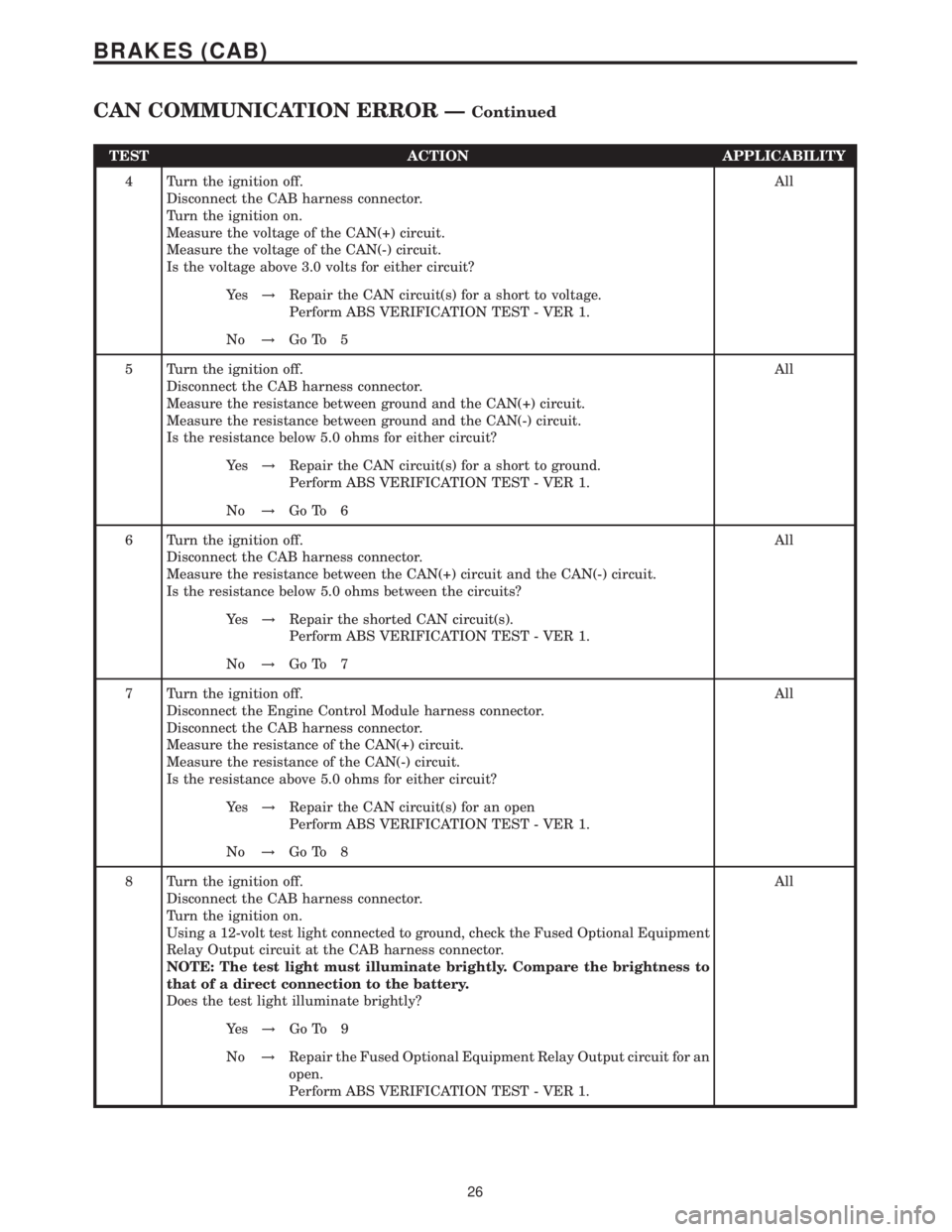
TEST ACTION APPLICABILITY
4 Turn the ignition off.
Disconnect the CAB harness connector.
Turn the ignition on.
Measure the voltage of the CAN(+) circuit.
Measure the voltage of the CAN(-) circuit.
Is the voltage above 3.0 volts for either circuit?All
Ye s!Repair the CAN circuit(s) for a short to voltage.
Perform ABS VERIFICATION TEST - VER 1.
No!Go To 5
5 Turn the ignition off.
Disconnect the CAB harness connector.
Measure the resistance between ground and the CAN(+) circuit.
Measure the resistance between ground and the CAN(-) circuit.
Is the resistance below 5.0 ohms for either circuit?All
Ye s!Repair the CAN circuit(s) for a short to ground.
Perform ABS VERIFICATION TEST - VER 1.
No!Go To 6
6 Turn the ignition off.
Disconnect the CAB harness connector.
Measure the resistance between the CAN(+) circuit and the CAN(-) circuit.
Is the resistance below 5.0 ohms between the circuits?All
Ye s!Repair the shorted CAN circuit(s).
Perform ABS VERIFICATION TEST - VER 1.
No!Go To 7
7 Turn the ignition off.
Disconnect the Engine Control Module harness connector.
Disconnect the CAB harness connector.
Measure the resistance of the CAN(+) circuit.
Measure the resistance of the CAN(-) circuit.
Is the resistance above 5.0 ohms for either circuit?All
Ye s!Repair the CAN circuit(s) for an open
Perform ABS VERIFICATION TEST - VER 1.
No!Go To 8
8 Turn the ignition off.
Disconnect the CAB harness connector.
Turn the ignition on.
Using a 12-volt test light connected to ground, check the Fused Optional Equipment
Relay Output circuit at the CAB harness connector.
NOTE: The test light must illuminate brightly. Compare the brightness to
that of a direct connection to the battery.
Does the test light illuminate brightly?All
Ye s!Go To 9
No!Repair the Fused Optional Equipment Relay Output circuit for an
open.
Perform ABS VERIFICATION TEST - VER 1.
26
BRAKES (CAB)
CAN COMMUNICATION ERROR ÐContinued
Page 362 of 2305
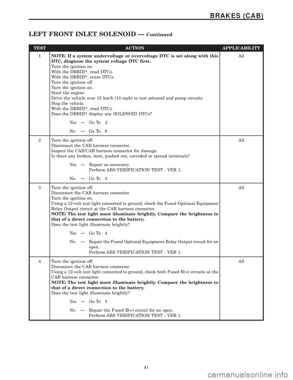
TEST ACTION APPLICABILITY
1NOTE: If a system undervoltage or overvoltage DTC is set along with this
DTC, diagnose the system voltage DTC first.
Turn the ignition on.
With the DRBIIIt, read DTCs.
With the DRBIIIt, erase DTCs.
Turn the ignition off.
Turn the ignition on.
Start the engine.
Drive the vehicle over 15 km/h (10 mph) to test solenoid and pump circuits.
Stop the vehicle.
With the DRBIIIt, read DTCs.
Does the DRBIIItdisplay any SOLENOID DTCs?All
Ye s!Go To 2
No!Go To 6
2 Turn the ignition off.
Disconnect the CAB harness connector.
Inspect the CAB/CAB harness connector for damage.
Is there any broken, bent, pushed out, corroded or spread terminals?All
Ye s!Repair as necessary.
Perform ABS VERIFICATION TEST - VER 1.
No!Go To 3
3 Turn the ignition off.
Disconnect the CAB harness connector.
Turn the ignition on.
Using a 12-volt test light connected to ground, check the Fused Optional Equipment
Relay Output circuit at the CAB harness connector.
NOTE: The test light must illuminate brightly. Compare the brightness to
that of a direct connection to the battery.
Does the test light illuminate brightly?All
Ye s!Go To 4
No!Repair the Fused Optional Equipment Relay Output circuit for an
open.
Perform ABS VERIFICATION TEST - VER 1.
4 Turn the ignition off.
Disconnect the CAB harness connector.
Using a 12-volt test light connected to ground, check both Fused B(+) circuits at the
CAB harness connector.
NOTE: The test light must illuminate brightly. Compare the brightness to
that of a direct connection to the battery.
Does the test light illuminate brightly?All
Ye s!Go To 5
No!Repair the Fused B(+) circuit for an open.
Perform ABS VERIFICATION TEST - VER 1.
41
BRAKES (CAB)
LEFT FRONT INLET SOLENOID ÐContinued
Page 396 of 2305
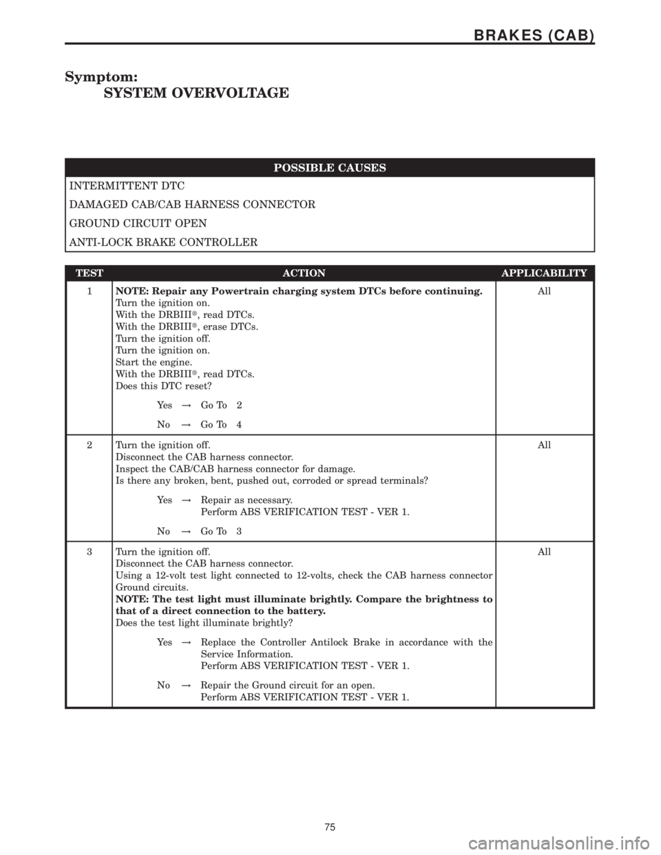
Symptom:
SYSTEM OVERVOLTAGE
POSSIBLE CAUSES
INTERMITTENT DTC
DAMAGED CAB/CAB HARNESS CONNECTOR
GROUND CIRCUIT OPEN
ANTI-LOCK BRAKE CONTROLLER
TEST ACTION APPLICABILITY
1NOTE: Repair any Powertrain charging system DTCs before continuing.
Turn the ignition on.
With the DRBIIIt, read DTCs.
With the DRBIIIt, erase DTCs.
Turn the ignition off.
Turn the ignition on.
Start the engine.
With the DRBIIIt, read DTCs.
Does this DTC reset?All
Ye s!Go To 2
No!Go To 4
2 Turn the ignition off.
Disconnect the CAB harness connector.
Inspect the CAB/CAB harness connector for damage.
Is there any broken, bent, pushed out, corroded or spread terminals?All
Ye s!Repair as necessary.
Perform ABS VERIFICATION TEST - VER 1.
No!Go To 3
3 Turn the ignition off.
Disconnect the CAB harness connector.
Using a 12-volt test light connected to 12-volts, check the CAB harness connector
Ground circuits.
NOTE: The test light must illuminate brightly. Compare the brightness to
that of a direct connection to the battery.
Does the test light illuminate brightly?All
Ye s!Replace the Controller Antilock Brake in accordance with the
Service Information.
Perform ABS VERIFICATION TEST - VER 1.
No!Repair the Ground circuit for an open.
Perform ABS VERIFICATION TEST - VER 1.
75
BRAKES (CAB)
Page 398 of 2305
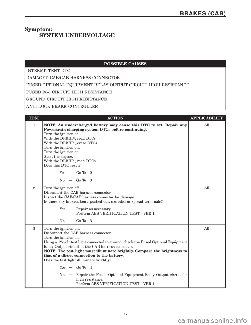
Symptom:
SYSTEM UNDERVOLTAGE
POSSIBLE CAUSES
INTERMITTENT DTC
DAMAGED CAB/CAB HARNESS CONNECTOR
FUSED OPTIONAL EQUIPMENT RELAY OUTPUT CIRCUIT HIGH RESISTANCE
FUSED B(+) CIRCUIT HIGH RESISTANCE
GROUND CIRCUIT HIGH RESISTANCE
ANTI-LOCK BRAKE CONTROLLER
TEST ACTION APPLICABILITY
1NOTE: An undercharged battery may cause this DTC to set. Repair any
Powertrain charging system DTCs before continuing.
Turn the ignition on.
With the DRBIIIt, read DTCs.
With the DRBIIIt, erase DTCs.
Turn the ignition off.
Turn the ignition on.
Start the engine.
With the DRBIIIt, read DTCs.
Does this DTC reset?All
Ye s!Go To 2
No!Go To 6
2 Turn the ignition off.
Disconnect the CAB harness connector.
Inspect the CAB/CAB harness connector for damage.
Is there any broken, bent, pushed out, corroded or spread terminals?All
Ye s!Repair as necessary.
Perform ABS VERIFICATION TEST - VER 1.
No!Go To 3
3 Turn the ignition off.
Disconnect the CAB harness connector.
Turn the ignition on.
Using a 12-volt test light connected to ground, check the Fused Optional Equipment
Relay Output circuit at the CAB harness connector.
NOTE: The test light must illuminate brightly. Compare the brightness to
that of a direct connection to the battery.
Does the test light illuminate brightly?All
Ye s!Go To 4
No!Repair the Fused Optional Equipment Relay Output circuit for
high resistance.
Perform ABS VERIFICATION TEST - VER 1.
77
BRAKES (CAB)
Page 431 of 2305

3.3.4 HANDLING NO TROUBLE CODE
PROBLEMS
After reading Section 3.0 (System Description
and Functional Operation), you should have a bet-
ter understanding of the theory and operation of the
on-board diagnostics and how this relates to the
diagnosis of a vehicle that may have a driveability-
related symptom or complaint. When there are no
trouble codes present, refer to the no trouble code
(*) tests.
3.4 USING THE DRBIIIT
Refer to the DRBIIItuser 's guide for instructions
and assistance with reading the DTCs, erasing the
DTCs, lab scope usage and other DRBIIItfunc-
tions.
3.4.1 DRBIIITDOES NOT POWER UP
If the LEDs do not light or no sound is emitted at
start up, check for loose cable connections or a bad
cable. Check the vehicle battery voltage at data link
connector cavity 16. A minimum of 11.0 volts is
required to adequately power the DRBIIIt. Check
for proper ground connection at data link connector
cavities 4 and 5.
If all connections are proper between the
DRBIIItand the vehicle or other devices, and the
vehicle battery is fully charged, an inoperative
DRBIIItmay be the result of a faulty cable or
vehicle wiring. For a blank screen, refer to the
appropriate diagnostic manual.
3.4.2 DISPLAY IS NOT VISIBLE
Low temperatures will affect the visibility of the
display. Adjust the contrast to compensate for this
condition.
4.0 DISCLAIMERS, SAFETY,
WARNINGS
4.1 DISCLAIMERS
All information, illustrations and specifications
contained in this manual are based on the latest
information available at the time of publication.
The right is reserved to make changes at any time
without notice.
4.2 SAFETY
4.2.1 TECHNICIAN SAFETY INFORMATION
WARNING: HIGH-PRESSURE FUEL LINES
DELIVER DIESEL FUEL UNDER EXTREME
PRESSURE FROM THE INJECTION PUMP TO
THE FUEL INJECTORS. THIS MAY BE AS
HIGH AS 23,200 PSI (1600 BAR). USE
EXTREME CAUTION WHEN INSPECTING
FOR HIGH-PRESSURE FUEL LEAKS. FUEL
UNDER THIS AMOUNT OF PRESSURE CAN
PENETRATE SKIN CAUSING PERSONAL
INJURY OR DEATH. INSPECT FOR
HIGH-PRESSURE FUEL LEAKS WITH A
SHEET OF CARDBOARD. WEAR SAFETY
GOGGLES AND ADEQUATE PROTECTIVE
CLOTHING WHEN SERVICING FUEL
SYSTEM.
WARNING: ENGINES PRODUCE CARBON
MONOXIDE THAT IS ODORLESS, CAUSES
SLOWER REACTION TIME AND CAN LEAD
TO SERIOUS INJURY. WHEN THE ENGINE IS
OPERATING, KEEP SERVICE AREA WELL
VENTILATED OR ATTACH THE VEHICLE
EXHAUST SYSTEM TO THE SHOP EXHAUST
REMOVAL SYSTEM.
Set the parking brake and block the wheels before
testing or repairing the vehicle. It is especially
important to block the wheels on front wheel drive
vehicles; the parking brake does not hold the drive
wheels.
When servicing a vehicle, always wear eye pro-
tection and remove any metal jewelry such as
watchbands or bracelets that might make electrical
contact.
When diagnosing powertrain system problems, it
is important to follow approved procedures where
applicable. These procedures can be found in the
8
GENERAL INFORMATION
Page 435 of 2305
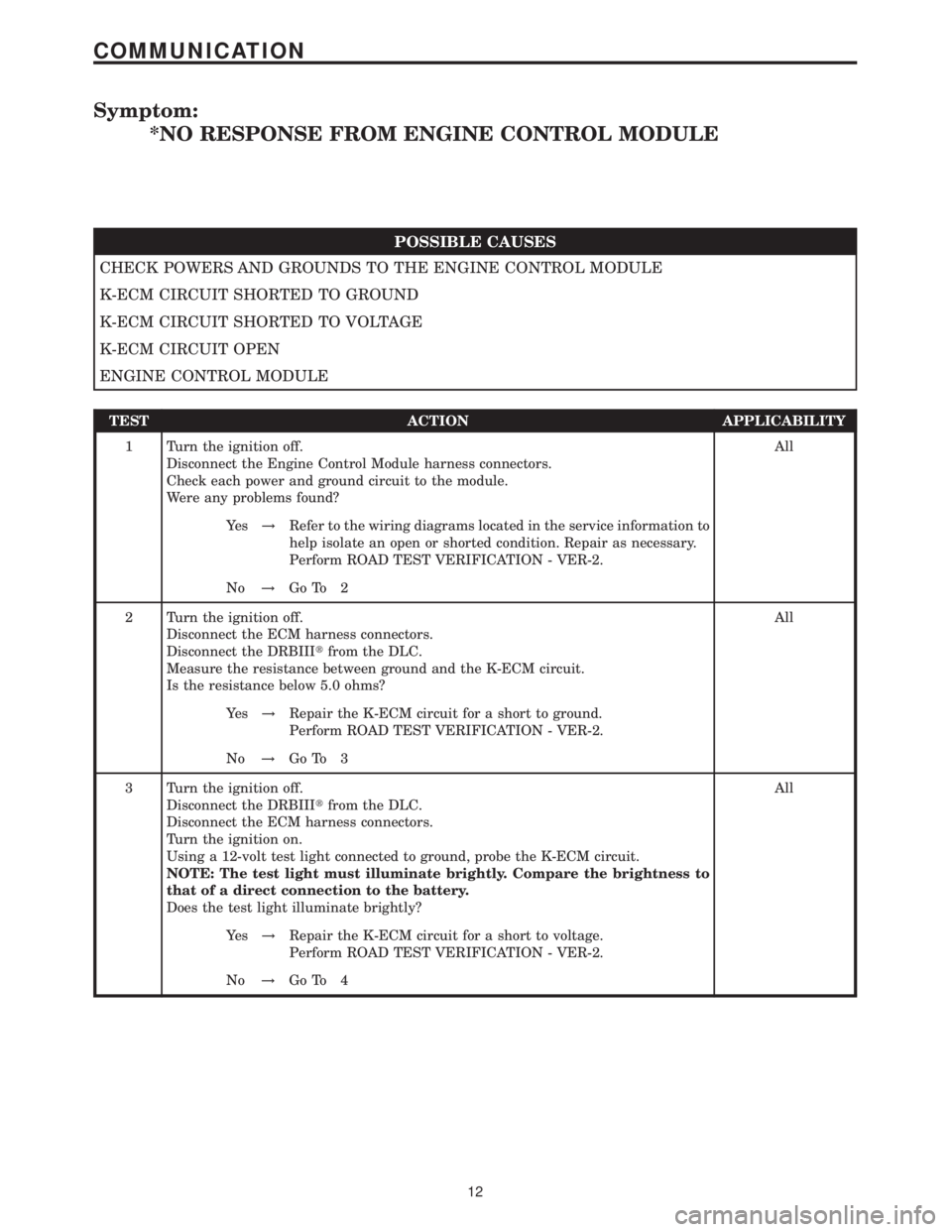
Symptom:
*NO RESPONSE FROM ENGINE CONTROL MODULE
POSSIBLE CAUSES
CHECK POWERS AND GROUNDS TO THE ENGINE CONTROL MODULE
K-ECM CIRCUIT SHORTED TO GROUND
K-ECM CIRCUIT SHORTED TO VOLTAGE
K-ECM CIRCUIT OPEN
ENGINE CONTROL MODULE
TEST ACTION APPLICABILITY
1 Turn the ignition off.
Disconnect the Engine Control Module harness connectors.
Check each power and ground circuit to the module.
Were any problems found?All
Ye s!Refer to the wiring diagrams located in the service information to
help isolate an open or shorted condition. Repair as necessary.
Perform ROAD TEST VERIFICATION - VER-2.
No!Go To 2
2 Turn the ignition off.
Disconnect the ECM harness connectors.
Disconnect the DRBIIItfrom the DLC.
Measure the resistance between ground and the K-ECM circuit.
Is the resistance below 5.0 ohms?All
Ye s!Repair the K-ECM circuit for a short to ground.
Perform ROAD TEST VERIFICATION - VER-2.
No!Go To 3
3 Turn the ignition off.
Disconnect the DRBIIItfrom the DLC.
Disconnect the ECM harness connectors.
Turn the ignition on.
Using a 12-volt test light connected to ground, probe the K-ECM circuit.
NOTE: The test light must illuminate brightly. Compare the brightness to
that of a direct connection to the battery.
Does the test light illuminate brightly?All
Ye s!Repair the K-ECM circuit for a short to voltage.
Perform ROAD TEST VERIFICATION - VER-2.
No!Go To 4
12
COMMUNICATION
Page 444 of 2305

TEST ACTION APPLICABILITY
1NOTE: If DTC P1611, P2306 or P2332 is present with this DTC, diagnose
DTCs P1611, P2306 or P2332 before diagnosing this DTC.
NOTE: Inspect all air intake and turbocharger related tubes for damage,
restriction or poor connection. Any of these conditions can cause a this DTC
to set.
NOTE: If the ECM detects and stores a DTC, the ECM also stores the
engine/vehicle operating conditions under which the DTC was set. Some of
these conditions are displayed on the DRB at the same time the DTC is
displayed.
NOTE: Before erasing stored DTCs, record these conditions. Attempting to
duplicate these conditions may assist when checking for an active DTC.
Turn the ignition on.
With the DRBIIIt, erase the ECM DTCs.
Test drive the vehicle.
With the DRBIIIt, read the ECM DTCs.
Does the DRB III display a Mass Air Flow Sensor DTC?All
Ye s!Go To 2
No!Go To 16
2NOTE: Check the ECM for other ECM DTC's related to circuits that are
open, shorted to ground or low voltage problems.
Does the DRB also display these type of DTC's?All
Ye s!Go To 3
No!Go To 4
3 Turn the ignition off.
Disconnect the ECM harness connectors.
Turn the ignition on.
Connect a jumper wire between ground and the Engine Control Relay Signal circuit
in ECM C2 harness connector cavity 44.
Using a 12-volt test light connected to ground, check the Fused Engine Control Relay
Output circuits at the ECM C1 harness connector cavities 1, 3 and 5.
Does the test light illuminate brightly for each circuit?All
Ye s!Go To 4
No!Refer to symptom list and perform Checking the ECM Power and
Grounds.
Perform ROAD TEST VERIFICATION - VER-2.
4NOTE: A malfunctioning EGR system can cause this DTC to set. Refer to
symptom Checking the EGR System in the Driveability category to check
EGR system operation.
Turn the ignition off.
Disconnect the MAF Sensor harness connector.
Turn the ignition on.
Measure the voltage of the MAF Sensor 5 Volt Supply circuit in MAF Sensor harness
connector.
Is the voltage between 4.8 and 5.2 volts?All
Ye s!Go To 5
No!Go To 12
21
DRIVEABILITY - DIESEL
P0100-MASS AIR FLOW SENSOR SIGNAL VOLTAGE TOO LOW Ð
Continued