Page 1891 of 3229

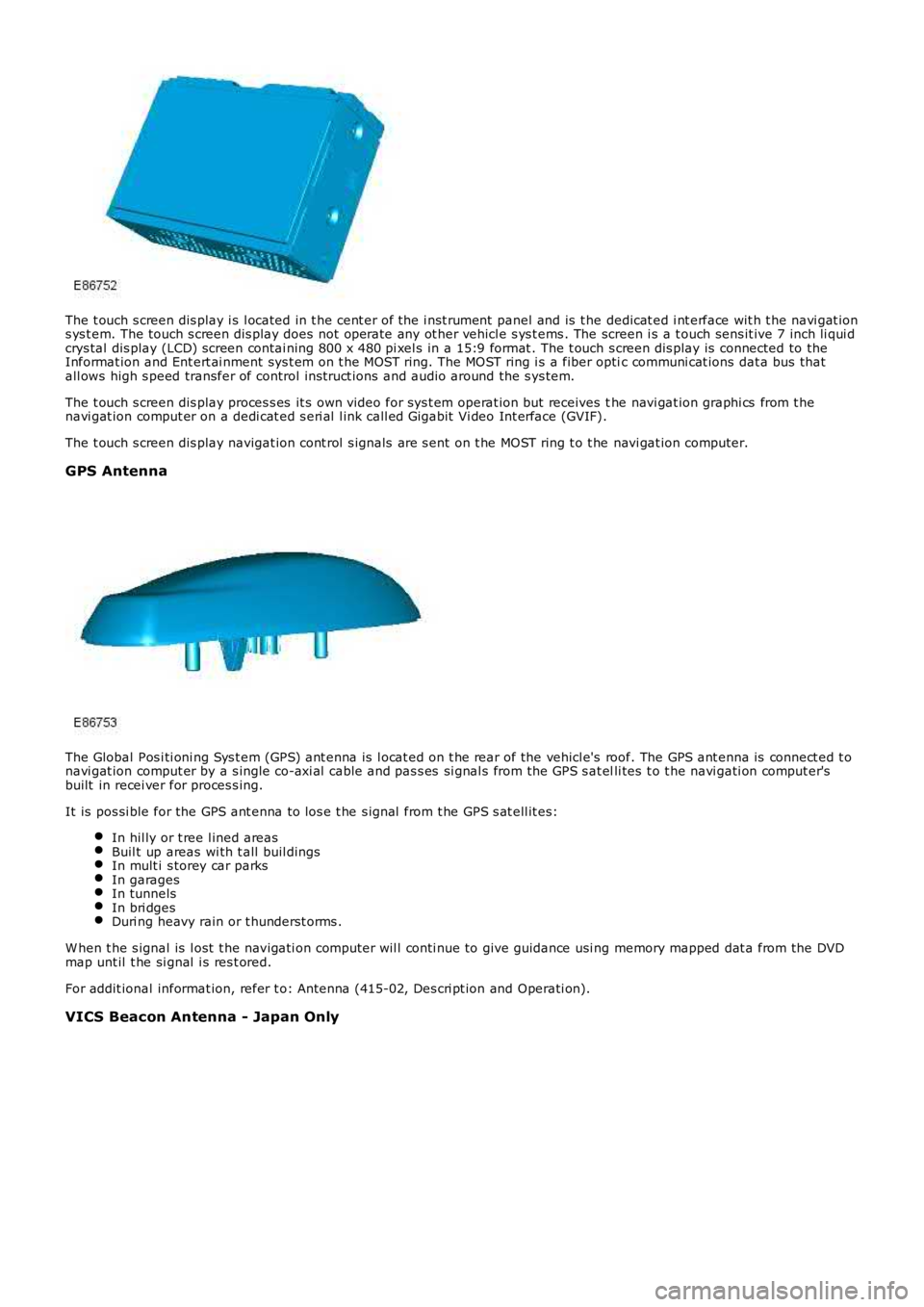
The t ouch s creen dis play i s l ocated in t he cent er of the i nst rument panel and is t he dedicat ed i nt erface wit h t he navi gat ions ys t em. The touch s creen dis play does not operate any ot her vehicl e s ys t ems . The screen i s a t ouch sens it ive 7 inch li qui dcrys tal dis play (LCD) screen contai ning 800 x 480 pi xel s in a 15:9 format . The t ouch s creen dis play is connected to theInformat ion and Ent ert ai nment sys t em on t he MOST ring. The MOST ring i s a fiber optic communi cat ions dat a bus thatall ows high s peed transfer of control ins truct ions and audio around the s ys tem.
The t ouch s creen dis play proces s es it s own video for sys t em operat ion but receives the navi gat ion graphi cs from t henavi gat ion comput er on a dedi cat ed s eri al l ink call ed Gigabit Vi deo Int erface (GVIF).
The t ouch s creen dis play navigat ion cont rol s ignals are s ent on t he MOST ring t o t he navi gat ion computer.
GPS Antenna
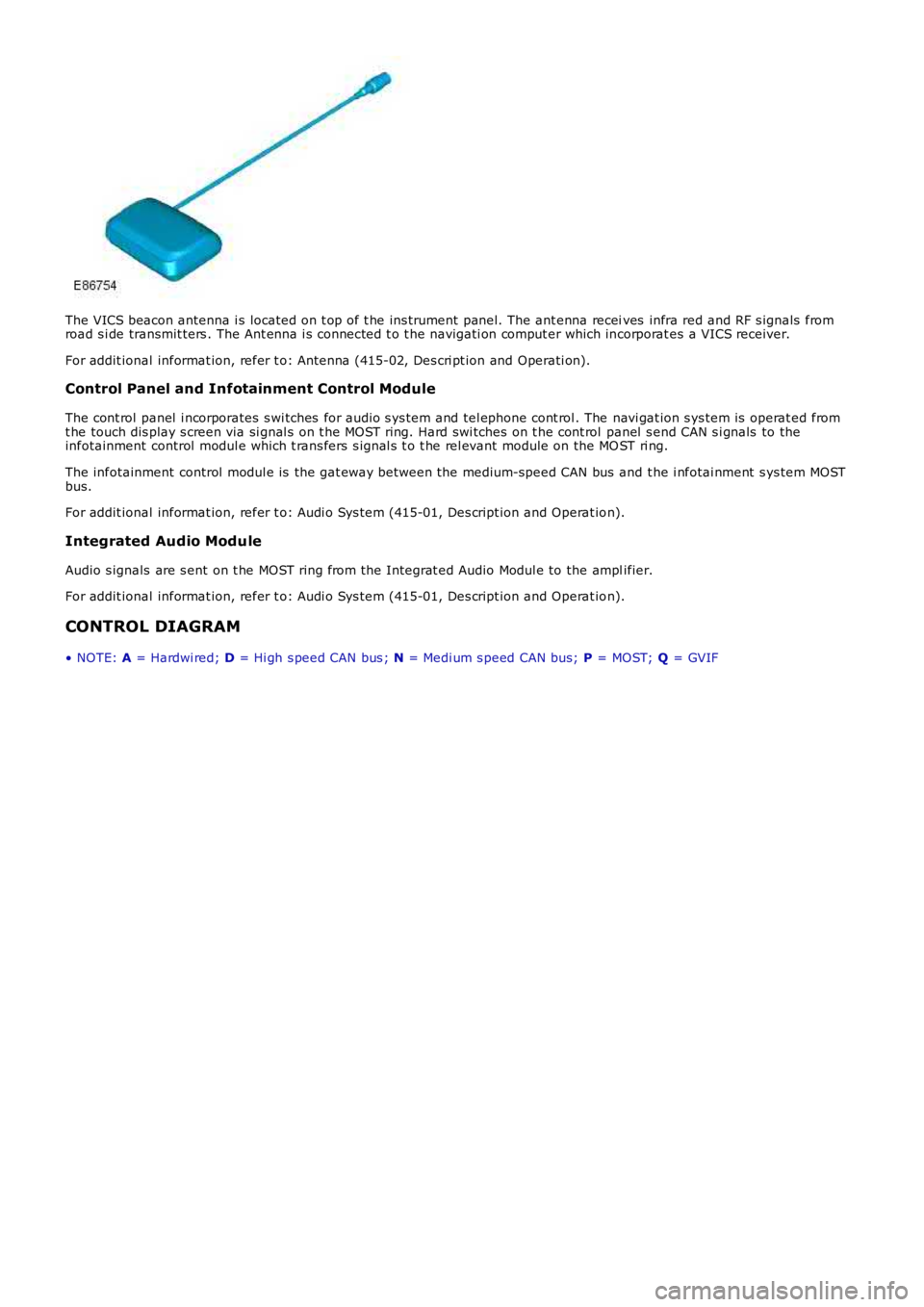
The Global Pos i ti oni ng Sys t em (GPS) ant enna is l ocat ed on t he rear of the vehicl e's roof. The GPS ant enna is connect ed t onavi gat ion comput er by a s ingle co-axi al cable and pas s es si gnal s from the GPS s at elli tes t o t he navi gati on comput er'sbuilt in recei ver for proces s ing.
It is pos si ble for the GPS ant enna to los e t he s ignal from t he GPS s at ell it es:
In hil ly or t ree l ined areasBuil t up areas wi th t all buil dingsIn mult i s torey car parksIn garagesIn tunnelsIn bri dgesDuri ng heavy rain or t hunderst orms .
W hen t he s ignal is l ost t he navigati on comput er wil l conti nue to give guidance usi ng memory mapped dat a from the DVDmap unt il t he si gnal i s res t ored.
For addit ional informat ion, refer t o: Antenna (415-02, Des cri pt ion and Operati on).
VICS Beacon Antenna - Japan Only
Page 1892 of 3229

The VICS beacon antenna i s located on t op of t he ins trument panel. The ant enna receives infra red and RF s ignals fromroad s i de transmit ters . The Ant enna i s connected t o t he navigati on comput er which incorporat es a VICS receiver.
For addit ional informat ion, refer t o: Antenna (415-02, Des cri pt ion and Operati on).
Control Panel and Infotainment Control Module
The cont rol panel i ncorporates s wi tches for audio s ys tem and tel ephone cont rol . The navi gat ion s ys tem is operat ed fromt he touch dis play s creen via si gnal s on t he MOST ring. Hard swi tches on t he cont rol panel s end CAN s i gnals to theinfotainment control modul e which t rans fers s ignal s t o t he rel evant module on the MOST ri ng.
The infotainment control modul e is the gat eway bet ween the medium-speed CAN bus and t he i nfotai nment s ys tem MOSTbus.
For addit ional informat ion, refer t o: Audi o Sys tem (415-01, Des cript ion and Operat ion).
Integrated Audio Module
Audio s ignals are s ent on t he MOST ring from the Integrat ed Audio Modul e to the amplifier.
For addit ional informat ion, refer t o: Audi o Sys tem (415-01, Des cript ion and Operat ion).
CONTROL DIAGRAM
• NOTE: A = Hardwi red; D = Hi gh s peed CAN bus ; N = Medi um s peed CAN bus; P = MOST; Q = GVIF
Page 1893 of 3229
ItemPart NumberDescription
1-Speakers2-Int egrated audio modul e
3-Ant i-lock brake s ys tem (ABS) cont rol module
4-Cent ral juncti on box (CJB)5-Global pos it ioning s ys tem (GPS) antenna
6-Vehi cl e Informat ion and Communi cat ion Sys tem (VICS) beacon antenna - Japan onl y
7-Traffic Mes s age Channel (TMC) antenna ampl ifier - Europe only8-Navi gat ion computer
9-Touch s creen dis play (TSD)
10-Audi o ampli fi er11-Infot ainment cont rol module (ICM)
Page 1897 of 3229
Publi s hed: 11-May-2011
Information and Entertainment System - Audio Unit
Removal and Inst all ati on
Removal
• NOTE: Removal s t eps in t his procedure may cont ain i nst all ati on det ail s.
Refer t o: Ins trument Panel Consol e (501-12 Ins t rument Panel andConsol e, Removal and Ins t al lat ion).1.
2.
3.
Page 1898 of 3229
4. NOTE: Do not dis ass embl e further if t he componenti s removed for acces s onl y.4.
5. CAUTION: Duri ng ins t al lat ion t he t op edge oft he bracket s mus t be ali gned wit h t he top edge of t heaudio unit . Failure t o do s o may res ult in damage tot he vehi cl e.
5.
Installation
To i nst all , revers e t he removal procedure.1.
Page 1903 of 3229
Publi s hed: 11-May-2011
Information and Entertainment System - Audio Unit Antenna
Removal and Inst all ati on
Removal
• NOTE: Removal s t eps in t his procedure may cont ain i nst all ati on det ail s.
Remove t he li ft gat e upper trim panel .
Refer t o: Li ft gate Trim Panel (501-05 Interi or Trim and
Ornament ati on, Removal and Ins tal lat ion).
1. Remove t he audi o unit antenna.
T orque: 10 Nm 2.
Installation To i nst all , revers e t he removal procedure.
1.
Page 1907 of 3229
Publi s hed: 11-May-2011
Information and Entertainment System - Rear Auxiliary Audio Controls
Removal and Inst all ati on
Removal
Remove t he coi n t ray.1.
Remove t he audi o cont rol s wit ch.2.
Installation
To i nst all , revers e t he removal procedure.1.
Page 1910 of 3229
Publi s hed: 11-May-2011
Antenna -
Torque SpecificationsDescriptionNmlb-ft
Audio uni t ant enna107
Cell ular phone ant enna107