Page 1878 of 3229

Dependi ng on the audi o s ys t em fit ted there are 3 di fferent s peaker configurat ions, these are:
Base audi o
2 Front door mounted mid/l ow range speakers2 Front door mounted hi gh range s peakers2 Rear door mount ed mi d/low range s peakers2 Rear door mount ed high range speakers
Mid range audio s ys tem
2 Front door mounted mid/l ow range speakers2 Front door mounted hi gh range s peakers2 Rear door mount ed mi d/low range s peakers2 Rear door mount ed high range speakersRear loads pace mounted s ub-woofer enclos ure
High line audio s ys t em
2 Front door mounted l ow range s peakers2 Front door mounted hi gh range s peakers2 Rear door mount ed mi d/low range s peakers2 Rear door mount ed high range speakersRear loads pace mounted s ub-woofer enclos ure2 Mi d range s peakers mounted on the i nst rument panel1 center fill s peaker cent ral ly l ocat ed in the i nst rument panel2 rear s urround s peakers mount ed in the rear C pil lars
CONTROL DIAGRAM SHEET 1 of 3
• NOTE: A = Hardwi red; N = Medium s peed CAN bus
Page 1879 of 3229
ItemPart NumberDescription
1-Bat tery2-BJB
3-CJB
4-Audio head uni t5-Front RH high range speaker
6-Rear RH hi gh range s peaker
7-Front RH mid/low range s peaker8-Rear RH mid/l ow range speaker
9-Front LH mid/low range s peaker
10-Rear LH mi d/l ow range s peaker11-Front LH hi gh range s peaker
Page 1880 of 3229
12-Rear LH high range s peaker
CONTROL DIAGRAM SHEET 2 of 3
• NOTE: A = Hardwi red; P = MOST
ItemPart NumberDescription
1-Bat tery2-Infot ainment cont rol module
3-Integrat ed audio modul e
4-Navigat ion computer5-Audio amplifier
Page 1882 of 3229
ItemPart NumberDescription
1-Bat tery2-Infot ainment cont rol module
3-Integrat ed audio modul e
4-Navigat ion computer5-Audio amplifier
6-Front center fill s peaker
7-Front RH mid range s peaker8-Front RH high range speaker
9-Rear RH hi gh range s peaker
10-Rear RH mid/l ow range speaker11-Front RH low range s peaker
Page 1884 of 3229
Publi s hed: 11-May-2011
Information and Entertainment System - Cellular Phone
Des cript ion and Operat ion
COMPONENT LOCATION
ItemPart NumberDescription1-Mi crophone
2-St eering wheel s wit ches
3-Audio amplifier4-Telephone cont rol module
5-Speakers
6-Integrat ed audio module (IAM)7-Infot ai nment cont rol module (ICM)
8-Cl ocks pring
OVERVIEW
The s ys t em al lows t he dri ver t o us e a Bl uet ooth equi pped cell ular phone hands et t hrough t he vehi cl es Informat ion andEntertainment s yst em.
• NOTE: There i s no physi cal connecti on (cradl e) bet ween t he phone hands et and the telephone cont rol module.Communicati ons bet ween t he 2 component s are purely Bl uet oot h. This can li mi t the avail abl e functi ons dependant on thehands et us ed.
Page 1887 of 3229
PRINCIPLES OF OPERATION
The phone sys tem is cont roll ed from the ICM and/or t he s teering wheel mount ed s wit ches . Control s i gnal s from t hes teeri ng wheel swi tches are sent via the clock s pri ng and the st eeri ng wheel module to the ICM. The ICM s ends controls ignals on t he MOST ring to the t elephone cont rol module. Audi o i s s ent on t he MOST ring to the audio ampl ifier and isoutput on t he vehi cl e s peaker s ys t em.
CONTROL DIAGRAM
• NOTE: A = Hardwi red; P = MOST
ItemPart NumberDescription
Page 1888 of 3229
1-Microphone
2-Telephone control modul e
3-Audi o ampl ifi er4-Speakers
5-Steeri ng wheel mount ed call s wit ches
6-Steeri ng wheel mount ed audio control s wi tches7-Clocks pring
8-Infotainment control modul e (ICM)
9-Int egrated audi o module (IAM)
Page 1889 of 3229

Publi s hed: 11-May-2011
Information and Entertainment System - Navigation System
Des cript ion and Operat ion
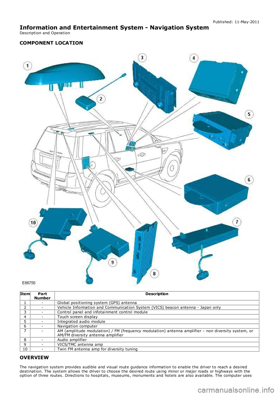
COMPONENT LOCATION
ItemPartNumberDescription
1-Gl obal pos it ioning s ys tem (GPS) antenna
2-Vehicl e Informat ion and Communi cat ion Sys tem (VICS) beacon antenna - Japan onl y3-Cont rol panel and i nfotai nment control modul e
4-Touch s creen dis play
5-Integrat ed audio modul e6-Navigat ion computer
7-AM (ampl it ude modulati on) / FM (frequency modul ati on) ant enna ampl ifier – non di versi ty sys t em, orAM/FM di versi ty ant enna ampli fier
8-Audio ampli fier
9-VICS/TMC ant enna amp10-Twi n FM ant enna amp for di versi ty tuning
OVERVIEW
The navi gat ion sys tem provides audible and vis ual rout e guidance informat ion t o enable t he dri ver t o reach a des i reddest inat ion. The sys t em all ows t he driver t o choos e t he desi red route us i ng minor or major roads or hi ghways wi th theopti on of three routes . Direct ions t o hos pit al s , museums , monuments and hot els are als o avail abl e. The computer us es