2006 LAND ROVER FRELANDER 2 heater
[x] Cancel search: heaterPage 1637 of 3229
Blower mot orHeater coreCabin ai r fil ter.For addit ional informat ion, refer t o: Air Di st ri buti on and Fi lt eri ng (412-01 Climat e Cont rol, Des cript ion andOperat ion).A/C evaporat or.For addit ional informat ion, refer t o: Air Condit ioning (412-01 Cli mat e Cont rol , Descripti on and Operat ion).Air i ntake flap and s tepper motor.For addit ional informat ion, refer t o: Cont rol Component s (412-01 Cli mat e Cont rol , Descripti on and Operat ion).Air di st ri but ion fl aps and s t epper mot ors .For addit ional informat ion, refer t o: Cont rol Component s (412-01 Cli mat e Cont rol , Descripti on and Operat ion).Temperature blend flaps and s t epper mot ors .For addit ional informat ion, refer t o: Cont rol Component s (412-01 Cli mat e Cont rol , Descripti on and Operat ion).Electric boos ter heater (if fi tt ed).For addit ional informat ion, refer t o: Electric Boos ter Heater (412-02 Auxi li ary Cl imat e Control, Des cript ion andOperat ion).
Blower Motor
The blower mot or compris es an open hub, centrifugal fan powered by an elect ric motor. Operati on of the bl ower motor iscont rol led by t he ATC module in conjuncti on wit h t he blower mot or control modul e. The ATC module provi des a Puls e W i dthModulated (PW M) si gnal t o t he blower motor control modul e based on the requi red bl ower speed. The bl ower motor cont rolmodule i nterprets the PW M s ignal as a blower mot or speed and controls t he volt age to t he blower mot or accordingl y.For addit ional informat ion, refer t o: Cont rol Component s (412-01 Cli mat e Cont rol , Descripti on and Operat ion).
Heater Core
The heat er core provi des t he heat s ource to warm the ai r bei ng s uppl ied i nto t he cabin. The heat er core is an alumi num, 2pass , fin and t ube heat exchanger ins t al led acros s t he widt h of t he heat er ass embly. Two al uminum tubes att ached t o t heheat er core extend t hrough t he engi ne bulkhead and connect t o t he engine cool ing s ystem. W hen the engine is runni ng,engi ne cool ant is const antl y ci rculat ed through the heater core by the coolant pump. For addit ional informati on, refer t o:
Engi ne Cool ing (303-03A Engine Cooli ng - I6 3.2L Petrol, Des cript ion and Operat ion),Engi ne Cool ing (303-03B Engine Cooli ng - TD4 2.2L Di esel , Descri pti on and Operat ion).
VENTILATION OUTLETS
The vent il ati on out let s all ow t he free flow of ai r through t he cabi n. The out let s are ins tall ed in the LH and RH rear quart erpanel s, behind the t ail lamps .
Each vent ilat ion out let compri ses a gril le covered by a s oft rubber fl ap, and i s effect ively a non-ret urn val ve. The flapsopen and cl ose aut omat ical ly depending on t he different ial between cabin and out si de air pres s ures .
PRINCIPLES OF OPERATION
Operat ion of t he heat ing and venti lat ion s ys tem is controlled by the ATC modul e.For addit ional informat ion, refer t o: Cont rol Component s (412-01 Cli mat e Cont rol , Descripti on and Operat ion).
Page 1641 of 3229
ItemPart NumberDescription
1-Met ering val ve2-Hous ing
3-Di aphragm
4-Temperat ure s ens or5-Out let pass age from evaporat or
6-Inlet pass age from evaporat or
The t hermos tat ic expans ion val ve meters the fl ow of refri gerant i nto the evaporator, to match t he refri gerant fl ow wi th t heheat load of the ai r pas s ing through t he evaporat or.
The t hermos tat ic expans ion val ve is a bl ock type valve l ocat ed behi nd the heat er as sembly, and att ached t o t he inl et andoutl et ports of t he evaporator. The t hermos t at ic expansi on valve cons i st s of an aluminum hous ing containi ng inlet andoutl et pas s ages . A ball and s pri ng met ering val ve is i nst all ed in the i nlet pass age and a t emperat ure s ensor i s ins t al led i nt he out let pas sage. The t emperature s ens or cons is t s of a t emperature s ens i ti ve tube connect ed to a diaphragm. Thebott om end of t he t emperature s ens it ive tube acts on the ball of t he met ering val ve. Pres s ure on top of t he diaphragm iscont rol led by t he evaporat or outl et t emperat ure conduct ed through the t emperat ure s ensi ti ve tube. The bott om of t hediaphragm sens es evaporat or out let pres s ure.
Liquid refrigerant flows t hrough t he metering valve i nto the evaporator. The res trict ion acros s t he metering valve reducest he pres sure and t emperature of the refrigerant . The res trict ion als o changes the l iquid st ream of refrigerant i nto a fi nes pray, to improve t he evaporati on proces s . As t he refri gerant pas s es through the evaporator, it abs orbs heat from t he airfl owing t hrough t he evaporat or. The i ncreas e i n t emperature caus es t he refri gerant to vapori ze and increas e in pres sure.
The t emperature and pres s ure of t he refri gerant l eavi ng the evaporat or act s on t he diaphragm and t emperat ure s ensi ti vet ube, which regul ate the met eri ng val ve openi ng and s o cont rol t he vol ume of refri gerant fl owing t hrough t he evaporat or.The warmer t he air flowi ng through the evaporator, the more heat avai lable to evaporat e refri gerant and thus t he greatervolume of refrigerant all owed through t he met eri ng val ve.
EVAPORATOR
The evaporat or is i nst all ed in the heater as s embly, bet ween t he blower and the heat er core, t o abs orb heat from t heexteri or or recirculat ed air. Low pres s ure, low temperat ure refrigerant changes from li qui d t o vapor i n t he evaporat or,absorbing l arge quant it ies of heat as it changes st ate.
Mos t of the moi s ture in the ai r pas s ing t hrough t he evaporat or condens es i nto wat er, whi ch drains out of the vehicl e bypass i ng through a drain tube t o t he unders ide of t he vehi cl e.
REFRIGERANT LINES
To mai nt ain si mil ar fl ow velocit ies around t he A/C s ys t em t he diamet er of t he refrigerant li nes varies t o s uit t he 2pres s ure/t emperat ure regi mes . Larger di ameter pipes are ins tal led i n t he low pres sure/t emperature regi me and s mall erdiamet er pi pes are i nst all ed in the hi gh pres sure/t emperature regi me.
Nylon l ined, low permeabi li ty rubber hos es are us ed i n t he low press ure li ne int o t he A/C compress or, and i n t he highpres s ure l ine from the condens er. The remainder of the refrigerant l ines are manufact ured from s teel.
Low and high press ure charging connecti ons are i ncorporated i nto the refrigerant li nes for s yst em s ervi ci ng.
Page 1654 of 3229
a utomati c control.
Air distri buti on can be re turned t o automatic control by pres sing the 'AUTO' swi tch loca ted in the ce nte r of the blower motorrotary controller. Thi s wi ll ill uminate the 'AUTO' LED and allow t he ATC module to control a ir di stribution in line wit h it s'comfort' algorithm
Air distri buti on is control led by 2 air dist ribution doors. The ATC module control s the position of the air dis tribution doors byprovi ding LIN bus me ssa ges to t he door ste pper motors . Ha ll ef fect sensors located wit hin the stepper mot ors inform t he ATCmodule t hat moveme nt of the st epper motors is taking place.
ECON - Single Zone Manual System
P ress ing the 'ECO N' moment ary swit ch on the control pa nel will swi tch off t he A/C s yste m. W he n s elected, the ATC modulewill t rans mit a mess age ove r the high speed CAN bus to the ECM re que sting the A/C compressor is dis able d. The ECMdisables the compres sor by de-e nergizing the A/C compress or control re lay loca ted in the BJB. The tell-tale LED in the swit chwill i lluminat e to ale rt the ve hicl e occupants tha t the system is in 'ECO N' mode .
W he n 'ECON' mode i s se lect ed, tempera ture control is s till a vai lable but no cooling of i ntake ai r wi ll ta ke place . The minimumoutput a ir te mpe rature f rom the sys tem will be ambient air tempera ture plus any heat pick up in the ai r int ake pat h.
A/C can be s witched back on by pres sing the 'ECON' swi tch a se cond time. This will als o extinguish the 'ECON' LED.
Stop/Sta rt Ve hicl es - From 2010 MY
From 2010 MY , t he 'ECON' switch wi ll be labeled ‘A/C’ to pre vent confus ion with the ‘Eco’ switch which operates the‘Stop/Sta rt’ a nd 'Gea r Change Indica tor' syst ems .For a ddit iona l inf ormation, re fer to: Starting Sys tem (303-06C Start ing Syst em - TD4 2.2L Diese l, Vehicles Buil t From:01-03-2009, Des cript ion and Ope rati on).
ECON - Dual Zone Automatic System
P ress ing the 'ECO N/O FF' momentary swi tch in the control pa nel will swi tch off t he A/C s yste m. W he n s elected, the ATCmodule will t rans mit a mess age ove r the high speed CAN bus to the ECM re que sting the A/C compress or is dis able d. The ECMdisables the compres sor by de-e nergizing the A/C compress or control re lay loca ted in the BJB. The 'ECO N' t ell-tale LED in t hes witch will il lumi nate to alert the ve hicle occupa nts that the sys tem is i n 'ECON' mode.
W he n 'ECON' mode i s se lect ed, tempera ture control is s till a vai lable but no cooling of i ntake ai r wi ll ta ke place . The minimumoutput a ir te mpe rature f rom the sys tem will be ambient air tempera ture plus any heat pick up in the ai r int ake pat h.
A second pre ss of the 'ECON/OFF' switch wil l ext inguish the 'ECO N' LED and illuminate the 'OFF' LED. W hen in 'OFF' mode t heATC module sets the blower mot or s pee d to 0. Air distri buti on i nto the cabi n wi ll remai n as pre viously sele cted. Al l LED's ont he control pane l wil l be ext inguishe d, a lthough night ti me illumina tion will remain acti ve.
• NO TE: W he n in 'OFF' mode , the he ated se at, heat ed windshie ld a nd heat ed rear window functions wi ll st ill be availa ble.
A thi rd press of t he 'ECO N/O FF' s wit ch re turns the s yste m to norma l (A/C) operation and extinguishes t he 'OFF' LED. Thes yste m can be re turned to a utomati c operat ion at a ny t ime by press ing the 'AUTO' swit ch mounted in t he cent ral (blowermotor) rotary control ler.
Stop/Sta rt Ve hicl es - From 2010 MY
From 2010 MY , t he 'ECON' switch wi ll be labeled ‘A/C’ to pre vent confus ion with the ‘Eco’ switch which operates the‘Stop/Sta rt’ a nd 'Gea r Change Indica tor' syst ems .For a ddit iona l inf ormation, re fer to: Starting Sys tem (303-06C Start ing Syst em - TD4 2.2L Diese l, Vehicles Buil t From:01-03-2009, Des cript ion and Ope rati on).
Programmed Defrost
The programmed def rost function is only ava ilable on ve hicl es fi tted wit h a dua l zone heati ng, vent ilat ion a nd A/C syst em.The f unction is s elected by press ing the 'PRO G' moment ary swit ch on the control pa nel. W hen s ele cted, the ATC moduleprovi des maximum winds hie ld de fros ting/de mist ing by confi guri ng t he s yste m a s follows:
'AUTO ' mode offIntake air set to fres h airAir di stribution se t to windshieldBlowe r motor spe ed s et t o maximumHeate d winds hiel d onRear window hea ter on.
W he n progra mmed defrost is sel ecte d, t he s et t emperat ure will remain unchanged. Programme d de fros t ca n be cancell ed bya ny of the following met hods:
P ress ing any air distribut ion moment ary swit chP ress ing the 'AUTO' s witch locate d in the center of t he blowe r motor rot ary cont rolle rP ress ing the 'PRO G' momenta ry s witch a second time .
• NO TE: Blower motor speed can be adjuste d wi thout te rmi nating programmed defrost.
Windshield Heater
The windshie ld heate r comprises 2 heate r el eme nts , LH and RH, bonded be twee n the glass laminat ions . The s yste m iss witched on by press ing the momentary swi tch l ocat ed on t he control panel . W hen selected, the ATC module t rans mits aheat ing request on t he high spe ed CAN bus to t he CJB. On rece ipt of the messa ge, the CJB ene rgiz es t he windshie ld heate rrelay loca ted in t he BJB by provi ding a ground path for t he relay coi l. The energized rela y provides a ba ttery fe ed t o bothheat er el eme nts . Aft er a period of 4 minutes the ATC module re moves t he request for windshie ld heati ng. The CJB the npowe rs down the windshield hea ter by re moving the ground pat h for the rel ay coil.
The ATC module will only reques t wi ndshield he ater ope rati on if the engine is runni ng. An e ngi ne s tatus si gnal is provi ded tot he ATC module by t he ECM over the high speed CAN bus.
Page 1655 of 3229
Rear Window Heater
The rear window hea ter comprise s a single heat er e leme nt bonded to the inner surf ace of t he glass . The syste m is swi tche don by pre ssing the mome nta ry s witch locate d on the control panel. W he n se lected, the ATC module tra nsmits a he atingreque st on the high spee d CAN bus to the CJB. On recei pt of the me ssa ge, the CJB energiz es t he rear window hea ter relayl ocat ed i n the Auxilia ry Junct ion Box (AJB) by providing a ground pa th for the re lay coil. The energiz ed relay provide s a bat teryf eed to t he heat er e leme nt. Afte r a period of 12 minute s the ATC module re moves the heat ing request . The CJB then powe rsdown the rea r wi ndow he ate r by removing the ground pa th f or t he relay coil .
The ATC module will only reques t re ar window heate r opera tion if the e ngine is running. An engine stat us s ignal is provide d tot he ATC module by t he ECM over the high speed CAN bus.
Exterior Mirror Heaters
O peration of the ext erior mirror heat ers is fully a utomat ic a nd re qui res no input from the driver. The exterior mirror hea tersa re a ctive when the ambient air tempera ture is below 5°C (41°F) and e ngine coolant te mpe rature i s be low 65° C (149° F).Ambi ent air a nd engine coola nt t empera ture val ues are provided by the ECM on the high speed CAN bus. O n re ceipt of the set emperat ure values, the CJB det ermines if e xterior mirror he ating is require d.
The CJB requests exterior mirror hea ting by transmit ting a high spe ed CAN bus mes sage to bot h the drivers and pa sse ngerdoor module s. The door modules provide fee d and ground paths to the respecti ve e xterior mirror he ating el eme nts . W hena mbi ent and engine cool ant tempera ture ris es a bove the va lues sta ted earl ier, the CJB transmi ts a high speed CAN busmess age to the door module s ca nce lling the hea ting reques t.
Seat Heaters
O peration of the sea t he aters is controll ed by the ATC module on re ceipt of a heati ng reque st f rom either of the se at heat ermomenta ry s witches loca ted on the cont rol pane l. The s witches are mounte d in the LH and RH rota ry controllers. A singlepress of a se at heat er switch wi ll implement low level heati ng a nd illumina te a tell-tale LED. A second pre ss of the switch willi mple me nt high l eve l hea ting and ill uminate 2 te ll-t ale LED's. A third press of t he s witch will turn t he s eat hea ter off.
Seat hea ting request s are transmitte d from the ATC module to the seat hea ter control modules on the LIN bus . Two se atheat er control modul es a re f itted, one under each front seat . The se at heat er control modules provide an e lect rical supply tot he s eat hea ter e lement s and a tempera ture sensor loca ted in t he s eat cus hion.
The s eat hea ter cont rol module provides a 5 V reference fee d to the sea t he ate r te mpe rature s ensor. The s eat hea tert emperat ure sensor is an NTC thermistor. By monitoring the ret urne d voltage, t he control module can calculate thet emperat ure of t he s eat. If t he t empera ture rise s above the target tempera ture , the control module wi ll dis abl e operat ion oft he heat er e leme nts .
Page 1703 of 3229
Publi s hed: 11-May-2011
Climate Control - Heater Core
Removal and Inst all ati on
Removal
Di sconnect t he bat t ery ground cable.
Refer t o: Specificati ons (414-00 Bat tery and Charging Sys tem -General Informat ion, Specificati ons).
1.
Drai n t he cool ing s ys tem.
Refer t o: Cool ing Sys tem Drai ni ng, Fi lli ng and Bleeding (303-03AEngine Cooli ng - I6 3.2L Petrol, General Procedures).
2.
Remove t he s el ect or lever.
Refer t o: Sel ect or Lever As sembl y (307-05 Aut omat icTrans mi ss ion/Transaxle Ext ernal Cont rol s , Removal andInst all at ion).
3.
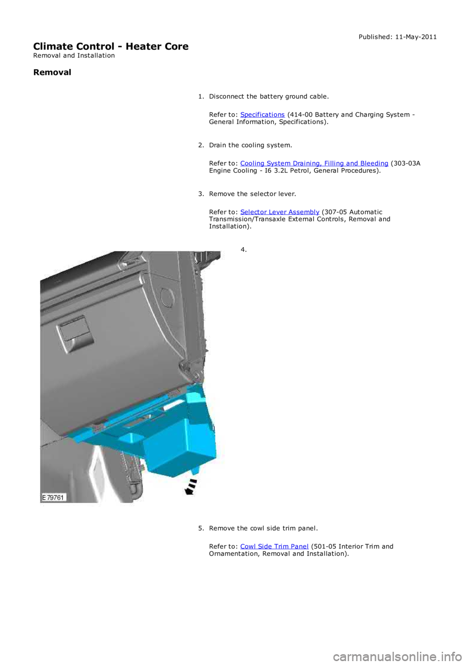
4.
Remove t he cowl s ide trim panel .
Refer t o: Cowl Si de Tri m Panel (501-05 Interior Tri m andOrnament ati on, Removal and Ins tal lat ion).
5.
Page 1718 of 3229
Publi s hed: 11-May-2011
Climate Control - Heater Core and Evaporator Core Housing
Removal and Inst all ati on
Removal
Make t he SRS s ys t em s afe.1.
Remove t he ins trument panel.
Refer t o: Ins trument Panel - TD4 2.2L Dies el (501-12 Inst rumentPanel and Cons ole, Removal and Inst all at ion).Refer t o: Ins trument Panel - I6 3.2L Pet rol (501-12 Ins t rument Paneland Consol e, Removal and Ins t al lat ion).
2.
Remove t he cl ocks pri ng.
Refer t o: Clocks pri ng (501-20B Supplement al Res t raint Sys tem,Removal and Ins tall ati on).
3.
Remove t he ins trument cl ust er.
Refer t o: Ins trument Clus ter (413-01 Ins t rument Clus t er, Removaland Inst all at ion).
4.
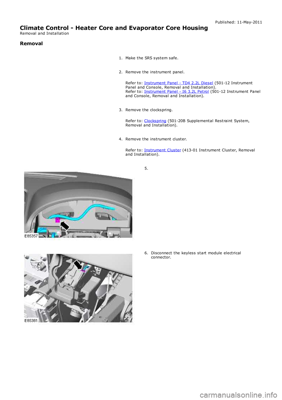
5.
Di sconnect t he keyl es s s t art module el ect ri calconnector.6.
Page 1737 of 3229
Publi shed: 26-Jul-2011
Auxiliary Heating - Fuel Fired Booster Heater
Diagnosi s and Tes ti ng
Overview
For informati on on t he des cri pti on and operati on of the s ys tem, refer t o s ect ion 412-02 -REFER to:
Fuel Fired Boos t er Heat er (412-02B Auxil iary Cli mate Cont rol, Des cri pt ion and Operati on),Fuel Fired Boos t er Heat er (412-02B, Des cript ion and Operat ion),Fuel Fired Boos t er Heat er (412-02B Auxil iary Cli mate Cont rol, Removal and Ins t al lat ion),Fuel Fired Boos t er Heat er Fuel Pump (412-02B Auxili ary Cl imat e Control, Removal and Ins tall ati on),Fuel Fired Boos t er Heat er Cool ant Pump (412-02B Auxil iary Cli mate Cont rol, Removal and Ins t al lat ion),Fuel Fired Boos t er Heat er Glow Pl ug And Burner As sembl y (412-02B Auxi liary Cli mate Cont rol , Removal andIns tal lat ion).Auxi li ary Heat ing i n the works hop manual .
Inspection and Verification
1. Verify t he cus t omer concern.1.
2. Vis ually ins pect for obvious mechani cal or electrical fault s .2.
Visual inspectionMechanicalElectrical
Fuel fired heater as sembl y- Combus ti on air fan- Coolant inl et /out let- Heat exchanger- Temperat ure s ens or- Exhaus t- Fuel inlet- Ai r inlet- EvaporatorAuxili ary fuel pump and li nesAuxili ary coolant pump
Fus esHarness esEl ect ri cal connector(s )Cont roll er area network (CAN) ci rcuit sCont rol module(s)
3. If an obvious cause for an obs erved or report ed concern is found, correct t he caus e (if pos s ible) beforeproceeding t o t he next s t ep3.
4. Us e the approved di agnos ti c s ys t em or a s can t ool t o ret rieve any diagnos t ic t rouble codes (DTCs ) before movingont o t he sympt om chart or DTC i ndex.4.
CAUTION: Di agnos is by s ubs ti tut ion from a donor vehicle is NO T acceptabl e. Subs ti tut ion of cont rol modules doesnot guarant ee confirmat ion of a faul t, and may als o caus e addit ional fault s i n t he vehi cl e being t est ed and/or t he donorvehi cl e.
• NOTE: If the control modul e or a component i s s us pect and the vehicle remains under manufacturer warrant y, refer t o theW arranty Pol icy and Procedures manual (s ect ion B1.2), or determine i f any pri or approval programme is in operat ion, pri ort o the ins tall ati on of a new module/component.
• NOTE: Generic scan t ool s may not read the codes li st ed, or may read only 5-digi t codes . Match t he 5 digi ts from t he s cant ool t o t he fi rs t 5 di gi ts of the 7-digit code li s ted t o i dent ify the fault (the last 2 digi ts gi ve ext ra informati on read by themanufacturer-approved di agnos ti c s ys t em).
• NOTE: Check and recti fy bas ic faul ts before beginni ng diagnos t ic rout ines i nvol vi ng pinpoint t es t s.
• NOTE: Ins pect connect ors for s igns of water ingres s , and pins for damage and/or corros ion.
• NOTE: If DTCs are recorded and, aft er performi ng the pi npoi nt tes ts , a fault is not present , an int ermi tt ent concern maybe t he caus e. Always check for loose connect ions and corroded terminals .
The t abl e below l is t s all Diagnos ti c Trouble Codes (DTCs ) t hat could be logged in the Fuel Fi red Boos ter Heater Module, foraddi ti onal Di agnos is and Tes ti ng informat ion refer t o t he relevant Diagnosi s and Test ing Secti on
DTC index
For a compl ete lis t of all Di agnos ti c Trouble Codes (DTCs) t hat could be logged on this vehicle, pleas e refer to Sect ion100-00. REFER t o: Diagnost ic Troubl e Code (DTC) Index - DTC: Auxi li ary Heater Control Modul e (AHCM) (100-00 GeneralInformat ion, Des cript ion and Operat ion).
Page 1738 of 3229
Publi s hed: 11-May-2011
Auxiliary Climate Control -
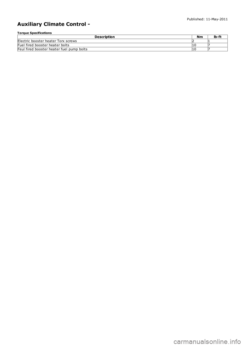
Torque SpecificationsDescriptionNmlb-ft
Electric boos ter heater Torx screws21
Fuel fired boost er heat er bol ts107Feul fired boost er heat er fuel pump bolt s107