2006 LAND ROVER FRELANDER 2 heater
[x] Cancel search: heaterPage 1122 of 3229
Publi s hed: 11-May-2011
Glow Plug System - Glow Plug System
Des cript ion and Operat ion
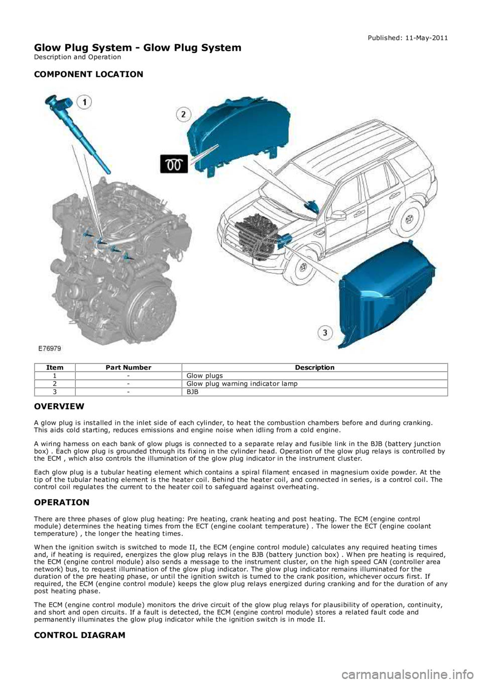
COMPONENT LOCATION
ItemPart NumberDescription
1-Glow plugs2-Glow plug warning i ndi cat or lamp
3-BJB
OVERVIEW
A gl ow plug i s i ns t alled in t he inl et si de of each cyli nder, to heat t he combus t ion chambers before and duri ng cranki ng.This ai ds col d s tarti ng, reduces emis s ions and engine nois e when idli ng from a col d engine.
A wi ri ng harnes s on each bank of glow plugs is connect ed t o a s eparat e rel ay and fusible li nk in t he BJB (bat t ery junct ionbox) . Each glow plug i s grounded through i ts fi xi ng in the cyli nder head. Operati on of the gl ow plug relays is cont roll ed byt he ECM , which al so cont rols the i ll uminati on of the gl ow plug indicator in the instrument cl us t er.
Each gl ow pl ug is a tubular heati ng element which cont ains a spi ral fi lament encas ed i n magnesi um oxide powder. At t het ip of t he tubular heati ng element is the heater coil . Behi nd the heat er coil , and connect ed i n s eries , is a cont rol coil . Thecont rol coil regulat es the current to the heat er coil t o s afeguard agains t overheat ing.
OPERATION
There are t hree phases of glow plug heati ng: Pre heati ng, crank heat ing and pos t heat ing. The ECM (engi ne cont rolmodule) determines t he heat ing ti mes from the ECT (engi ne cool ant temperat ure) . The lower t he ECT (engi ne coolantt emperature) , t he l onger t he heat ing t imes .
W hen t he i gni ti on s wit ch is s wi tched to mode II, t he ECM (engi ne cont rol module) calculates any requi red heat ing t imesand, i f heat ing is requi red, energizes the gl ow pl ug relays i n t he BJB (bat tery juncti on box) . W hen pre heati ng is required,t he ECM (engi ne cont rol module) als o s ends a mes s age to the i nst rument clus t er, on the high s peed CAN (cont roll er areanetwork) bus , to request i ll uminati on of the gl ow pl ug indicator. The gl ow pl ug indicator remains il lumi nat ed for thedurat ion of t he pre heati ng phase, or unti l the i gni ti on s wit ch is t urned t o t he crank pos it ion, whichever occurs fi rs t. Ifrequired, the ECM (engine control modul e) keeps t he glow pl ug rel ays energi zed during cranking and for the durati on of anypost heat ing phase.
The ECM (engi ne cont rol module) moni tors the drive circui t of the gl ow plug relays for pl aus i bi li ty of operat ion, cont inuit y,and s hort and open ci rcuit s . If a fault i s detected, the ECM (engine cont rol module) s tores a rel ated faul t code andpermanentl y il lumi nat es t he glow pl ug indicator whi le t he i gni ti on s wit ch is i n mode II.
CONTROL DIAGRAM
Page 1134 of 3229
module), regulates t he amount of exhaus t gas es reci rculated into the ai r int ake s ys tem. The ECM uses s i gnals fromvarious engine s ens ors and calculates a res pons e bas ed on t he embedded software algori thm t o cont rol exhaus t gasrecircul ati on. The ECM trans mi ts this cont rol s ignal t o t he valve's actuat or, which i s clos ed-loop controlled wit h t he mas sair flow (MAF) s ens or providi ng the feedback t o t he ECM.
COMPONENT DESCRIPTION
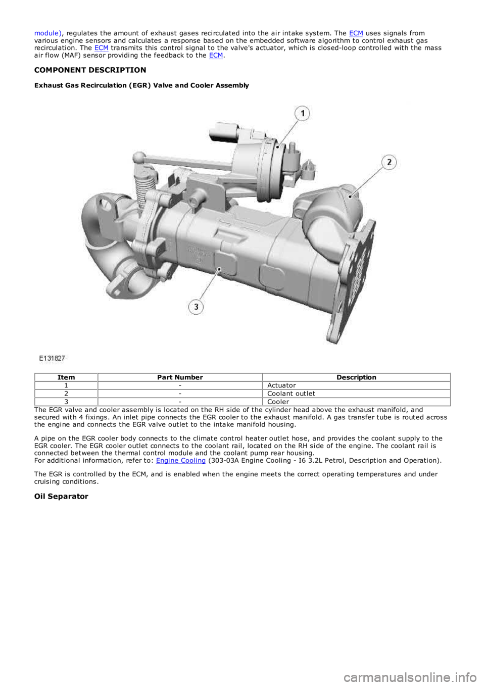
Exhaust Gas R ecirculation (EGR) Valve and Cooler Assembly
ItemPart NumberDescription1-Actuator
2-Coolant out let
3-CoolerThe EGR valve and cooler ass embl y is l ocat ed on t he RH s ide of t he cylinder head above t he exhaus t manifold, ands ecured wit h 4 fixi ngs . An i nl et pipe connects the EGR cooler t o t he exhaus t manifold. A gas t rans fer t ube is rout ed acros st he engi ne and connect s t he EGR valve out let t o the intake mani fold hous ing.
A pi pe on t he EGR cool er body connect s to the cl imat e cont rol heater outl et hos e, and provides t he cool ant s upply t o t heEGR cooler. The EGR cooler outl et connect s t o t he cool ant rail , locat ed on t he RH s ide of the engine. The cool ant rail isconnected bet ween the t hermal control modul e and the coolant pump rear hous ing.For addit ional informat ion, refer t o: Engi ne Cooling (303-03A Engine Cooli ng - I6 3.2L Pet rol, Des cri pt ion and Operati on).
The EGR i s cont rol led by t he ECM, and is enabled when t he engine meet s t he correct operati ng temperatures and undercruis i ng condit ions .
Oil Separator
Page 1214 of 3229
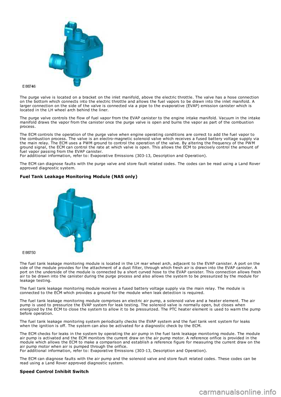
The purge valve i s located on a bracket on the i nlet manifold, above the el ect ri c throt t le. The val ve has a hos e connecti onon t he bott om whi ch connect s i nt o t he electric t hrot tl e and all ows t he fuel vapors to be drawn i nto the i nlet manifold. Alarger connect ion on t he s ide of t he valve i s connect ed via a pipe t o t he evaporati ve (EVAP) emis s ion canis ter whi ch islocated i n t he LH wheel arch behind t he li ner.
The purge valve controls t he flow of fuel vapor from t he EVAP cani st er to the engine intake mani fold. Vacuum in the intakemanifold draws the vapor from t he canis ter once the purge val ve is open and burns the vapor as part of the combus ti onprocess .
The ECM controls t he operati on of the purge val ve when engine operat ing condi ti ons are correct t o add t he fuel vapor t ot he combus ti on process . The valve i s an electro-magnet ic s olenoid valve whi ch receives a fused bat tery vol tage s upply vi at he main relay. The ECM us es a PW M ground t o cont rol t he operati on of the val ve. By al tering t he frequency of the PW Mground s ignal, t he ECM can cont rol t he rat e at whi ch val ve is open. Thi s all ows the ECM to precis ely control t he amount offuel vapor pas si ng from the EVAP canis ter.For addit ional informat ion, refer t o: Evaporat ive Emi s si ons (303-13, Des cript ion and Operat ion).
The ECM can diagnose fault s wi th the purge val ve and s tore fault relat ed codes . The codes can be read us i ng a Land Roverapproved diagnos t ic s yst em.
Fuel Tank Leakage Monitoring Module (NAS only)
The fuel t ank leakage moni toring module is l ocat ed in the LH rear wheel arch, adjacent to t he EVAP canis ter. A port on t hes ide of t he module provi des for t he att achment of a dus t fi lt er, t hrough which fres h air i s drawn i nto the EVAP canis ter. Aport on t he unders ide of t he module i s connected by a s hort curved hos e to t he EVAP canis ter. Thi s connecti on allows fres hair t o be drawn int o t he cani st er during t he purge proces s and als o al lows t he s yst em to be pres surized by t he module forleakage tes t ing.
The fuel t ank leakage moni toring module receives a fus ed bat tery vol tage s upply via the main relay. The modul e i sconnected t o t he ECM whi ch provides a ground for the modul e when l eak det ect ion i s required.
The fuel t ank leakage moni toring module compris es an elect ric ai r pump, a s olenoi d valve and a heat er el ement. The airpump i s used to press urize t he EVAP s ys t em for leak tes t ing. The sol enoi d valve is normall y open, but clos es whenenergized by t he ECM t o clos e t he s ys t em t o al low i t to be pres s urized. The PTC heater element is us ed t o warm t he pumpbefore operati on.
The fuel t ank leakage moni toring s yst em periodicall y checks the EVAP sys tem and t he fuel tank vent s ys t em for leakswhen t he ignit ion i s off. The s ys t em can als o be act ivated for a diagnos ti c check by t he ECM.
The ECM checks for leaks in t he s yst em by operati ng the ai r pump in the fuel tank leakage monit ori ng modul e. The modul eair pump i s acti vat ed and t he ECM monit ors the current draw on t he air pump motor. A reference ori fi ce is provi ded in t hemodule whi ch allows the ECM to make a comparis on and es t abl is h a reference figure for meas uring the current draw on theair pump motor when air i s pumped through the orifice.For addit ional informat ion, refer t o: Evaporat ive Emi s si ons (303-13, Des cript ion and Operat ion).
The ECM can diagnose fault s wi th the ai r pump and the sol enoi d val ve and s tore faul t relat ed codes . Thes e codes can beread us ing a Land Rover approved diagnos t ic s ys tem.
Speed Control Inhibit Switch
Page 1382 of 3229
14.
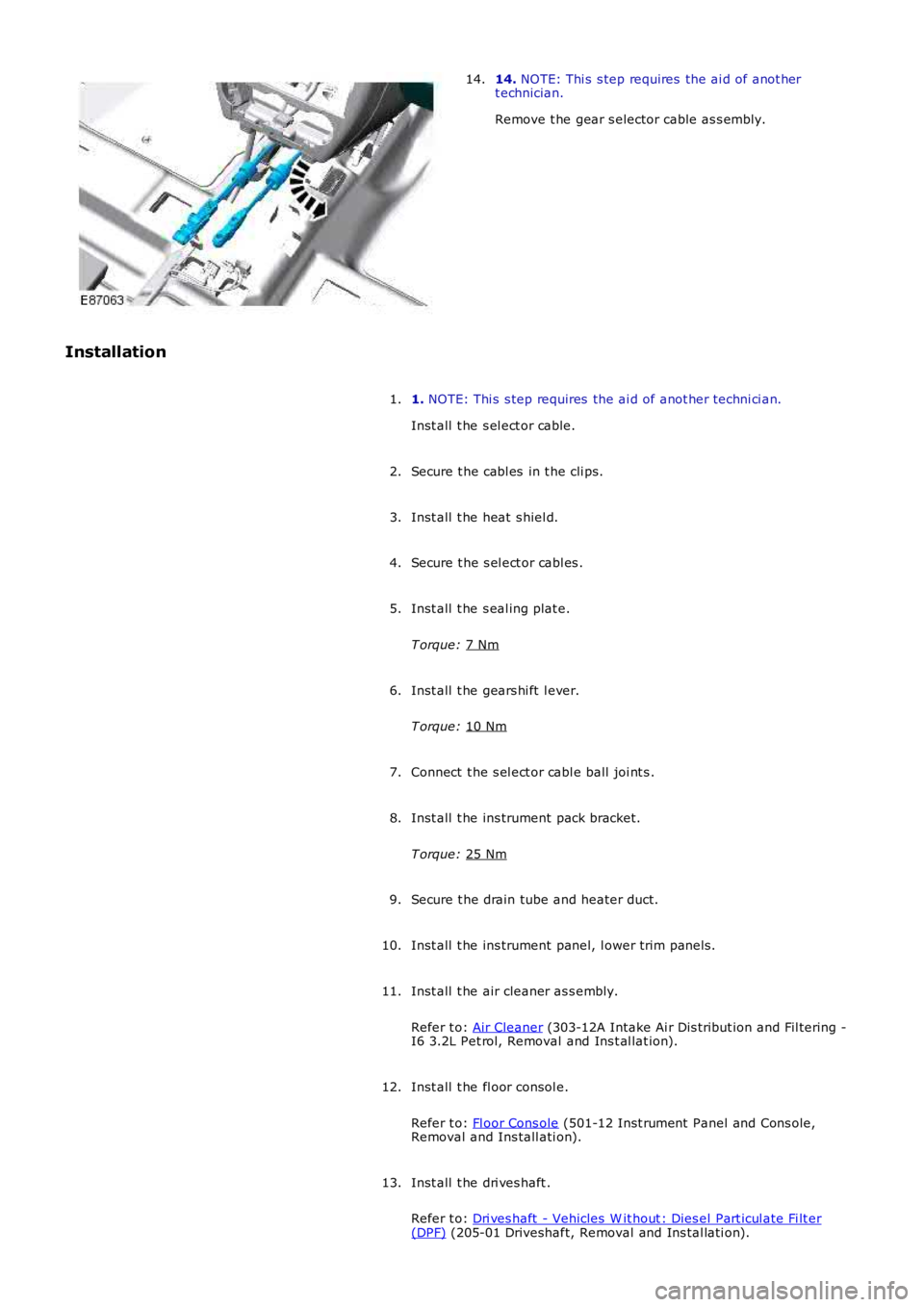
NOTE: Thi s s tep requires the ai d of anot her
t echnician.
Remove t he gear s elector cable as s embly.
14.
Installation 1. NOTE: Thi s s tep requires the ai d of anot her techni ci an.
Inst all t he s el ect or cable.
1.
Secure t he cabl es in t he cli ps.
2.
Inst all t he heat s hiel d.
3.
Secure t he s el ect or cabl es .
4.
Inst all t he s eal ing plat e.
T orque: 7 Nm 5.
Inst all t he gears hi ft l ever.
T orque: 10 Nm 6.
Connect t he s el ect or cabl e ball joi nt s .
7.
Inst all t he ins trument pack bracket.
T orque: 25 Nm 8.
Secure t he drain tube and heater duct.
9.
Inst all t he ins trument panel, l ower trim panel s.
10.
Inst all t he air cleaner as s embly.
Refer t o: Air Cleaner (303-12A Intake Ai r Dis tribut ion and Fil tering -
I6 3.2L Pet rol, Removal and Ins t al lat ion).
11.
Inst all t he fl oor consol e.
Refer t o: Fl oor Cons ole (501-12 Inst rument Panel and Cons ole,
Removal and Ins tall ati on).
12.
Inst all t he dri ves haft .
Refer t o: Dri ves haft - Vehicles W it hout : Dies el Part icul ate Fi lt er (DPF) (205-01 Driveshaft, Removal and Ins tal lati on).
13.
Page 1483 of 3229
Inst all t he s eal ing plat e.
T orque: 7 Nm 6.
Connect t he s el ect or cabl e ball joi nt s .
7.
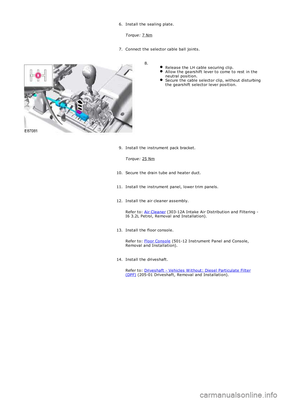
Releas e t he LH cabl e s ecuring cli p. All ow t he gears hift lever t o come t o rest in t he
neutral pos it ion. Secure t he cabl e s elect or clip, wi thout dis turbing
t he gears hi ft s elect or l ever pos it ion. 8.
Inst all t he ins trument pack bracket.
T orque: 25 Nm 9.
Secure t he drain tube and heater duct.
10.
Inst all t he ins trument panel, l ower trim panel s.
11.
Inst all t he air cleaner as s embly.
Refer t o: Air Cleaner (303-12A Intake Ai r Dis tribut ion and Fil tering -
I6 3.2L Pet rol, Removal and Ins t al lat ion).
12.
Inst all t he fl oor consol e.
Refer t o: Fl oor Cons ole (501-12 Inst rument Panel and Cons ole,
Removal and Ins tall ati on).
13.
Inst all t he dri ves haft .
Refer t o: Dri ves haft - Vehicles W it hout : Dies el Part icul ate Fi lt er (DPF) (205-01 Driveshaft, Removal and Ins tal lati on).
14.
Page 1563 of 3229
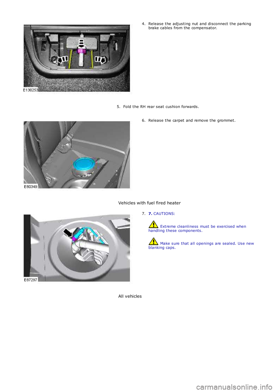
Releas e t he adjus ti ng nut and di sconnect t he parkingbrake cables from the compens at or.4.
Fold t he RH rear s eat cus hi on forwards .5.
Releas e t he carpet and remove t he grommet .6.
Vehicles with fuel fired heater
7. CAUTIONS:
Ext reme cl eanli ness must be exerci sed whenhandl ing t hese components .
Make s ure that all openings are sealed. Us e newblanking caps.
7.
All vehicles
Page 1567 of 3229
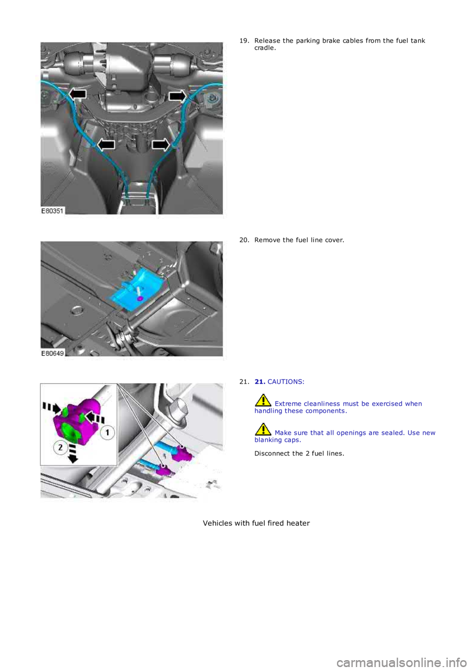
Releas e t he parking brake cables from t he fuel tankcradle.19.
Remove t he fuel li ne cover.20.
21. CAUTIONS:
Ext reme cl eanli ness must be exerci sed whenhandl ing t hese components .
Make s ure that all openings are sealed. Us e newblanking caps.
Di sconnect t he 2 fuel l ines.
21.
Vehicles with fuel fired heater
Page 1585 of 3229
The fuel deli very module flange i s s eal ed to the t ank wit h an O-ring and s ecured wi th a locki ng ring.
The lower part of t he fuel deli very module forms the fuel del ivery pot , and provides the locat ion for the in-t ank pump andt he 2 jet pumps . The delivery pot provi des a cons t ant res ervoir of fuel for t he engine drawn fuel supply. The engine fuels uppl y and ret urn l ines are immers ed in the del ivery pot .
The delivery pot is mai ntained full by t he 2 jet pumps . The i n-t ank pump draws fuel from wit hin the fuel deli very pot andforces the fuel t hrough t he 2 jet pumps . The flow of fuel t hrough each jet pump creat es a venturi effect t hat draws fuelfrom bot h s ides of t he fuel tank i nto the fuel deli very pot. Surpl us fuel entering the fuel deli very pot overflows into theus abl e s ide of t he fuel t ank.
A valve i s l ocated in t he l ower (usabl e tank s i de) jet pump s uppl y ori fi ce. The valve i s open when the i n-t ank pump isenergized and t he lower jet pump is s upplying fuel i nto the fuel del ivery pot . The val ve wil l cl os e when the i n-t ank pump isde-energized t o prevent fuel drai ni ng from the fuel del ivery pot .
The in-tank pump is energized by t he fuel pump relay l ocat ed in the Cent ral Juncti on Box (CJB). The Engine Cont rol Module(ECM) energi zes the fuel pump relay at al l ti mes when t he ignit ion i s in power modes 4 (Acces s ory) t o 9 (Engi ne crank).For addit ional informat ion, refer t o: Electroni c Engi ne Controls - 2.2L Dies el (303-14 El ect ronic Engine Cont rols - 2.2LDies el, Des cript ion and Operat ion).
A modi fi ed fuel delivery modul e i s ins tal led for col d climat e market vehicl es that feat ure a fuel fi red boos ter heater andauxi li ary fuel pump. The modified fuel del ivery modul e incorporat es a s eparate fuel supply line that connects t o anauxi li ary fuel pump, mounted on the ext erior RH si de of the tank. An addi ti onal fuel l ine connects the auxil iary fuel pumpt o the fuel fi red boos ter heat er.For addit ional informat ion, refer t o: Fuel Fired Boost er Heat er (412-02B Auxi liary Cli mate Cont rol , Des cri pti on andOperat ion).
Fuel Sender Units
The 2 MAPPS fuel s ender uni ts are located on eit her s ide of t he s addl e s haped tank, and connect t o t he int ernal elect ricalconnecti ons on the fuel del ivery modul e fl ange. Each s ens or provides an elect rical signal t o t he CJB t hat i s proport ionatet o the fuel level i n each s ide of t he tank.
The act ual fuel level i n t he t ank i s calculated by the CJB and t rans mit t ed via t he medium s peed Cont roll er Area Net work(CAN) bus t o t he ins t rument clus ter.
A warning l amp is incorporat ed in t he i ns t rument clus ter and wi ll il lumi nat e when t he fuel l evel is at, or below apredetermined l evel . On vehi cles wi th a high-l ine i nst rument clus ter, a mes s age is di spl ayed and a chi me i s s ounded t oinform the driver to refuel .
For addit ional informat ion, refer t o:
Ins trument Clus ter (413-01 Ins t rument Clus t er, Descripti on and Operat ion),Informat ion and Mes s age Cent er (413-08 Informati on and Mes sage Cent er, Descripti on and Operat ion).
Fuel Tank Breather Valve
The breat her valve i s located i n t he fuel t ank and is connected to the fuel deli very module fl ange vi a an i nt ernal breatherhose. The breat her valve al lows ai r to es cape and ent er the fuel tank t o compens at e for t he changing vol ume wit hin thet ank.
FUEL TANK FILLER