2006 LAND ROVER FRELANDER 2 heater
[x] Cancel search: heaterPage 796 of 3229
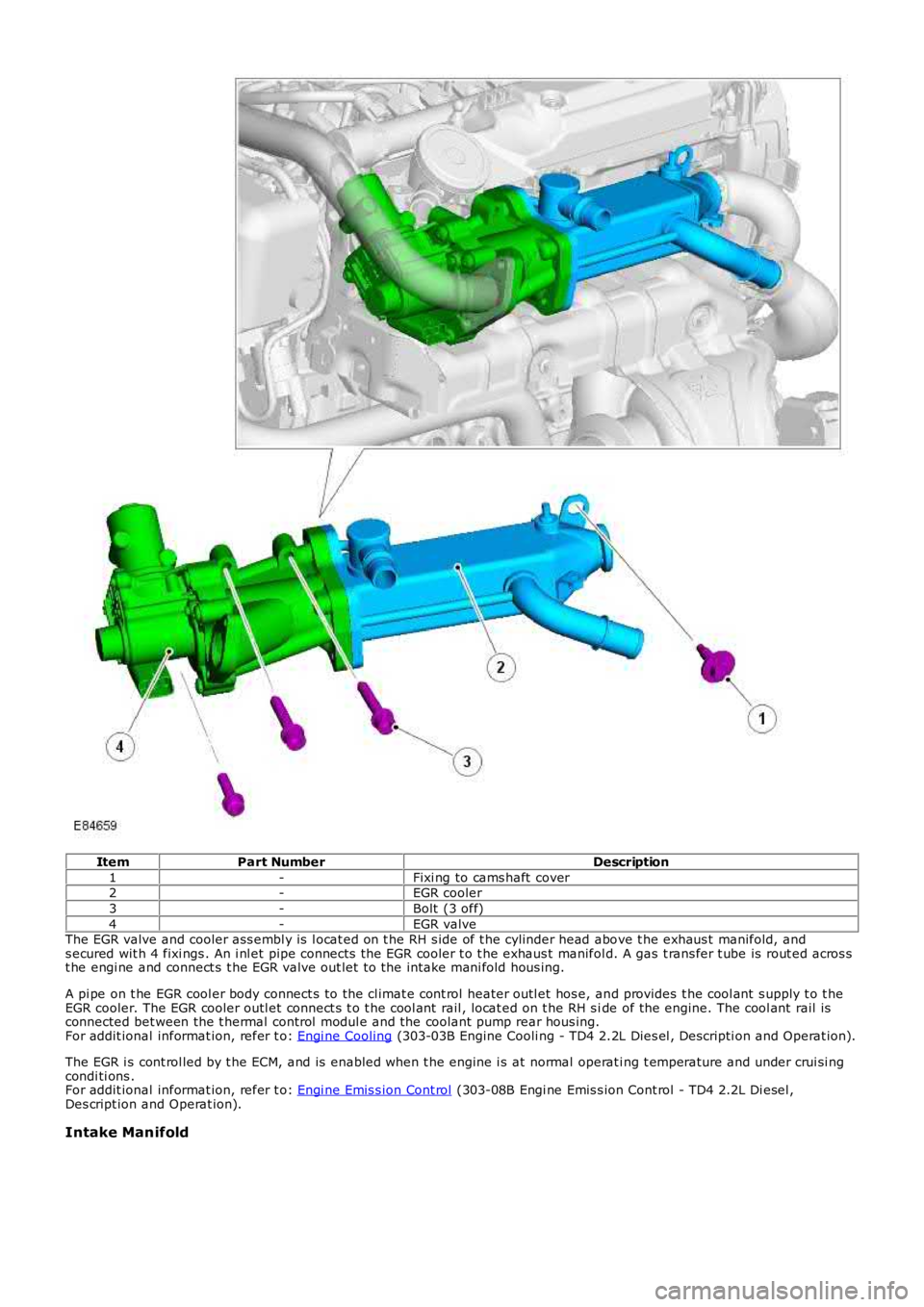
ItemPart NumberDescription
1-Fixi ng to cams haft cover2-EGR cooler
3-Bolt (3 off)
4-EGR valveThe EGR valve and cooler ass embl y is l ocat ed on t he RH s ide of t he cylinder head above t he exhaus t manifold, ands ecured wit h 4 fixi ngs . An i nl et pipe connects the EGR cooler t o t he exhaus t manifold. A gas t rans fer t ube is rout ed acros st he engi ne and connect s t he EGR valve out let t o the intake mani fold hous ing.
A pi pe on t he EGR cool er body connect s to the cl imat e cont rol heater outl et hos e, and provides t he cool ant s upply t o t heEGR cooler. The EGR cooler outl et connect s t o t he cool ant rail , locat ed on t he RH s ide of the engine. The cool ant rail isconnected bet ween the t hermal control modul e and the coolant pump rear hous ing.For addit ional informat ion, refer t o: Engi ne Cooling (303-03B Engine Cooli ng - TD4 2.2L Dies el , Descripti on and Operat ion).
The EGR i s cont rol led by t he ECM, and is enabled when t he engine i s at normal operati ng t emperature and under crui si ngcondi ti ons .For addit ional informat ion, refer t o: Engi ne Emis s ion Cont rol (303-08B Engi ne Emis s ion Cont rol - TD4 2.2L Di esel ,Des cript ion and Operat ion).
Intake Manifold
Page 901 of 3229
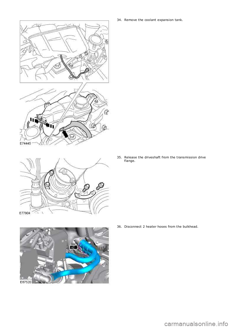
Remove t he cool ant expans i on tank.34.
Releas e t he dri ves haft from the t rans mi ss i on driveflange.35.
Di sconnect 2 heater hos es from t he bulkhead.36.
Page 939 of 3229
5-Engine coolant pump
6-Exhaus t Gas Recircul at ion (EGR) valve cool er
7-Heat er connect ion hos es8-Cl imat e cont rol s yst em heat er matrix
9-Thermal control modul e
10-Auxil iary coolant pump (col d cli mate vehi cl es )11-Fuel Fi red Boos ter Heater (FFBH) - (cold cli mate vehi cl e)
OVERVIEW
The main requirement of t he TD4 di es el engi ne cool ing s ys tem is t o regul ate t he engines operati ng t emperature, wit hi n anopti mum range for all ambi ent and operat ing condit ions. Addit ional functi ons of t he cool ing s ys tem are to provi de heat ingt o the cl imat e cont rol s ys tem, and cooling for the EGR s ys t em, engi ne lubri cat ion sys tem, and t rans mi ss i on lubri cat ions ys t em (automat ic t rans mis s ion model s only).
The cool ing s ys tem pipes and hoses feature qui ck rel eas e coupl ings t o all ow eas y acces s to the sys tem.
On cold cl imat e market vehicles , the cooli ng s ys t em i s modified t o i ncorporate a FFBH and auxi liary cool ing pump. TheFFBH provides auxili ary heati ng t o t he vehi cl e cabi n.For addit ional informat ion, refer t o: Fuel Fired Boost er Heat er (412-02B Auxi liary Cli mate Cont rol , Des cri pti on andOperat ion).
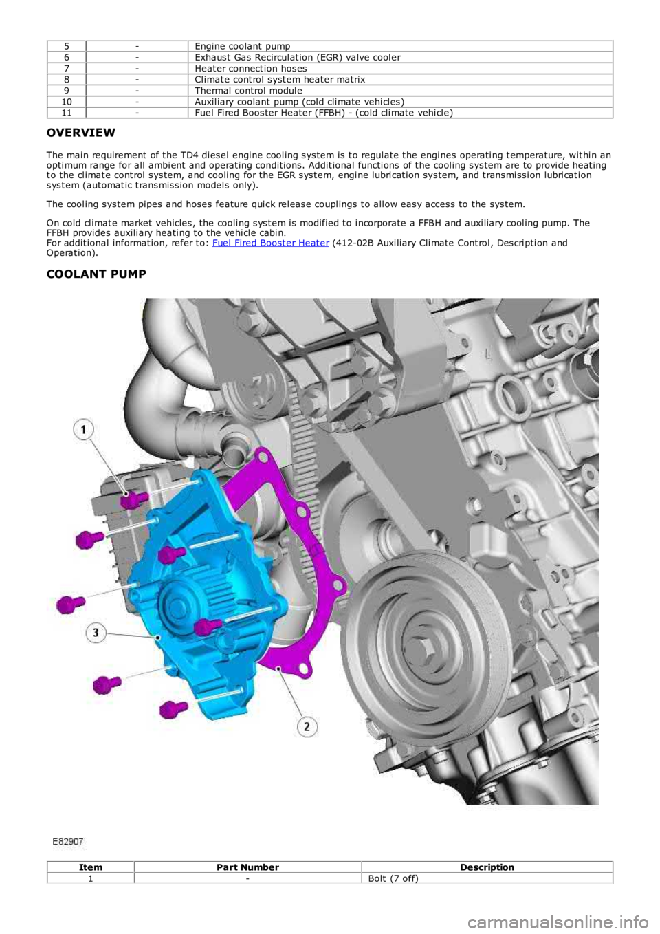
COOLANT PUMP
ItemPart NumberDescription
1-Bolt (7 off)
Page 940 of 3229
2-Gas ket
3-Coolant pump
The cent ri fugal type coolant pump is mount ed at t he front of t he engine and s ecured wit h 7 bol ts . The pump i s direct lydri ven by the t oothed cams haft belt and circul ates coolant through t he cylinder block and cyl inder head, cool ing s ys temand heat er circuit .
The cool ant pump is able to del iver cool ant at a rate of 215 lit ers /min (57 US gal lons /min) at 2.8 bar (41 psi ), creat ing amaximum external s yst em press ure of 2.0 bar (30 psi ).
A l arge di amet er cool ant rail located on the Ri ght -Hand (RH) s ide of t he engine connects the rear of t he coolant pumphous i ng to the t hermal control modul e outl et . A connect ion on t he cool ant rail at t he cool ant pump hous ing end provi dest he coolant return from t he EGR cooler.
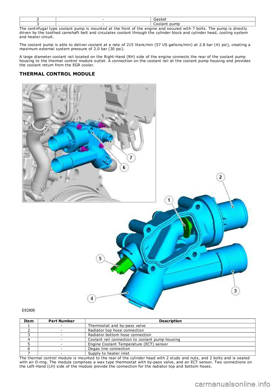
THERMAL CONTROL MODULE
ItemPart NumberDescription
1-Thermos t at and by-pass val ve
2-Radiat or top hos e connecti on3-Radiat or bot tom hose connect ion
4-Coolant rai l connect ion to coolant pump hous ing
5-Engine Coolant Temperat ure (ECT) sens or6-Degas l ine connecti on
7-Supply t o heater i nl et
The t hermal cont rol module i s mounted to t he rear of t he cyl inder head wit h 2 s t uds and nut s , and 2 bolt s and is s ealedwit h an O-ring. The module compri s es a wax t ype thermos t at wit h by-pas s valve, and an ECT s ens or. Two connect ions ont he Left-Hand (LH) s i de of the module provide t he connecti on for t he radi at or top and bot tom hoses .
Page 944 of 3229

CLIMATE CONTROL HEATER MATRIX
The heat er mat rix is i nst all ed in the cli mate cont rol as sembl y, l ocat ed on t he vehi cl e cent er li ne bet ween t he ins trumentpanel and t he engi ne bulkhead. Two pi pes pas s t hrough t he bul khead i nto the engine compart ment and connect to as uppl y and a return cool ing s yst em heat er hos e. The coolant s uppl y hos e is connect ed t o an outl et on the thermal controlmodule. The cool ant return hose is connect ed to the EGR cool er.
The mat ri x is cons truct ed from al uminum wit h t wo end t anks i nterconnect ed wit h t ubes. Aluminum fins are locatedbetween t he t ubes and t rans fer heat to the pas s ing air. Coolant is s upplied to the heater mat ri x at all t imes when theengi ne is running.For addit ional informat ion, refer t o: Heati ng and Vent il ati on (412-01 Cl imat e Control, Des cript ion and Operat ion).
ENGINE COOLANT
The long-l ife engine coolant is s i licate free and is not t o be mixed wi th convent ional engi ne coolant .
The cool ing s ys tem cont ai ns approximat el y 8 l it ers (8.5 US quart s) of a 50/50 wat er and l ong li fe coolant concentrati on.
PRINCIPLES OF OPERATION
Cooling Sys tem Flow at Normal Operat ing Temperat ure
Page 1104 of 3229
25-Fuel fired heat er (i f fi tt ed)
26-Auxili ary coolant pump **
* Vehicles wit hout fuel fired heat er.
** Vehicles wi th fuel fi red heater.
INTELLIGENT TECHNOLOGY
New and revi s ed components as di s cus s ed in this secti on have been developed t o ensure t hat al l vehicl e s ys t ems operatevirtuall y uninterrupt ed in a Stop/St art cycl e.
Voltage Quality Module
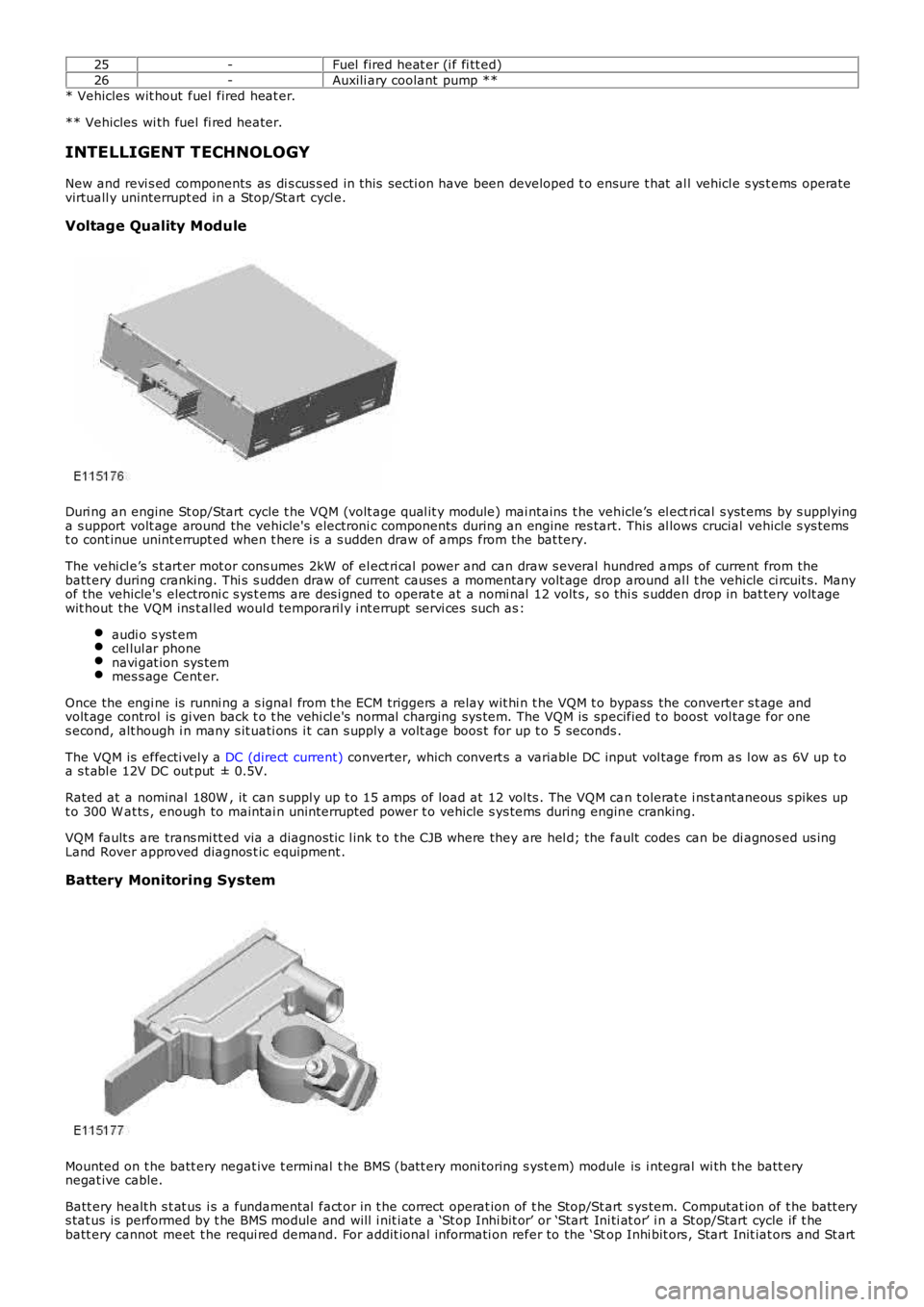
Duri ng an engine St op/Start cycle t he VQM (volt age qual it y module) mai ntains t he vehicle’s el ect ri cal s yst ems by s upplyinga s upport volt age around the vehicle's electroni c components during an engine res tart. This al lows crucial vehicle s ys temst o cont inue unint errupt ed when t here i s a s udden draw of amps from the bat tery.
The vehi cl e’s s t art er mot or cons umes 2kW of el ect ri cal power and can draw s everal hundred amps of current from thebatt ery during cranking. Thi s s udden draw of current causes a momentary volt age drop around al l t he vehicle ci rcuit s. Manyof the vehicle's electroni c s ys t ems are des i gned t o operat e at a nomi nal 12 volt s , so thi s s udden drop in bat tery volt agewit hout the VQM ins t al led woul d temporaril y i nt errupt servi ces such as :
audi o s yst emcel lul ar phonenavi gat ion sys temmes s age Cent er.
Once the engi ne is runni ng a s ignal from t he ECM triggers a relay wit hi n t he VQM t o bypass the converter s t age andvolt age control is gi ven back t o t he vehi cl e's normal charging sys tem. The VQM is specified t o boost vol tage for ones econd, alt hough i n many s it uati ons i t can s upply a volt age boos t for up t o 5 seconds .
The VQM is effecti vel y a DC (direct current) converter, which convert s a variable DC input vol tage from as l ow as 6V up t oa s t abl e 12V DC out put ± 0.5V.
Rated at a nominal 180W , it can s uppl y up t o 15 amps of load at 12 vol ts . The VQM can t olerat e i ns t ant aneous s pikes upt o 300 W at ts , enough to maintai n uninterrupt ed power t o vehicle s ys tems during engine cranking.
VQM fault s are trans mi tt ed via a diagnost ic l ink t o t he CJB where they are hel d; the fault codes can be di agnos ed us ingLand Rover approved diagnos t ic equipment .
Battery Monitoring System
Mounted on t he batt ery negat ive t ermi nal t he BMS (batt ery moni toring s yst em) module is i ntegral wi th t he batt erynegat ive cable.
Batt ery healt h s t at us i s a fundamental fact or in t he correct operat ion of t he Stop/St art s ys tem. Computat ion of t he batt erys tat us is performed by t he BMS module and will i nit iate a ‘St op Inhi bit or’ or ‘Start Ini ti at or’ i n a St op/Start cycle if t hebatt ery cannot meet t he requi red demand. For addit ional informati on refer to the ‘Stop Inhi bit ors , Start Init iat ors and St art
Page 1108 of 3229
however remain i ll uminated.
A ‘st all recovery’ event is the onl y s tat e when t he Stop/St art s yst em wil l permit t he engine t o be s t art ed when thet ransmis s ion i s in gear; hence t he requirement for t he cl utch pedal to be full y depres sed. If the s t all recovery fai ls and t heengi ne does not res tart, t he dri ver wi ll be reques ted vi a t he Mess age Center t o ‘s elect neutral ’ to at t empt anot her rest art .
If the engine does not res t art aft er thi s request t he ‘st all recovery’ mode wil l ti me-out and deact ivate. At t his point t he‘Eco’ i con in t he i ns t rument panel wi ll exti ngui sh and the light s usual ly as s ociat ed wi th an engi ne st all wi ll il lumi nat e. As ares ult t he dri ver will be requi red to perform a convent ional engi ne res tart.
Alt hough st all recovery i s a feat ure of t he St op/Start sys t em i t is pos si ble for it t o acti vat e i ndependent ly from t heStop/St art parameters . For exampl e:
If the St op/Start s ys t em has been deact ivated by the driver st all recovery wi ll s ti ll funct ion.Stal l recovery wil l act ivate at ambi ent temperat ures as l ow as (minus ) - 2°C, whereas the St op/Syst em operat ingt emperature threshold is above 4°C.Different t o t he operat ion of t he Stop/St art s yst em, s tal l recovery wil l st il l functi on when the vehicle is t owing;refer to the ‘Trail er Towi ng’ s ect ion.
• NOTE: As t he neces s ary cri teria will not have been sat is fi ed when t he vehi cl e i s at the beginning of a journey s t allrecovery wi ll not functi on. For exampl e, if t he vehi cl e s tal ls when l eavi ng the garage or driveway a convent ional engineres t art wi ll be required.
Trailer Towing
The Stop/St art s ys tem wil l aut omati cal ly di sabl e when t rail er light s are det ect ed by t he CJB via s ignals from t he t rail ermodule, t hi s informat ion i s t hen trans mi tt ed t o t he ECM. It i s not pos s ibl e for t he s ys t em t o det ect when a trai ler powerplug i s ins ert ed i n the vehicl e’s t owi ng s ocket s o it us es operat ion of t he trail er l ights as it s indi cat or.
The t rail er towing sys tem inhi bi ts St op/St art as i t is pos s ible that trail er power requirements could interfere wit h t heoperati on of the bat tery monit ori ng s ys t em. In parti cul ar, a t rai ler batt ery could revers e t he feed current t o t he vehicleduri ng an engi ne cranking event , t hi s coul d pos si bly:
Confus e t he bat t ery monit ori ng s ys t em i nto det ect ing an unreal is t ically smal l current at engi ne cranking.Rupture the fus e as sociat ed wit h t he t rail er modul e.
Climate Control System
• NOTE: The ‘ECON’ butt on has been renamed ‘A/C’ to prevent confus ion wi th the St op/St art s yst em ‘Eco’ s wit ch.
A number of changes have been made to the l ogi c and operati on of climat e control system, wit hi n a St op/St art cycle to:
maint ain occupant comfortprevent winds hi eld mis ti ngcons erve bat tery power.
This has been achi eved by the ATC (automat ic t emperat ure control) module monit oring and varyi ng, as necess ary variousclimate control funct ions wi thi n a St op/Start cycle.
In s ome circums t ances t he ATC has t he capabil it y to inhibit an engi ne s hut down or init iat e an engine rest art wit hi n aStop/St art cycle. Thi s i s achi eved by t he ATC module communi cat ing wit h t he CJB on the medi um s peed CAN. The variousoverri de functi ons the ATC has in a St op/St art cycl e are di s cus s ed bel ow:
Coolant temperat ure
The ATC module wil l i nhibit an engine shut down or i nit iat e an engine res t art wi thi n a St op/Start cycle if t he coolantt emperature fal ls below the calculat ed t hreshol d to s upport t he cabin t emperat ure s et by t he vehi cl e occupant s .
W i nds hiel d demis t ing
The variant of cli mate control fi tt ed t o the vehicl e influences t he s oft ware changes that have been made. For exampl e, thebase cl imat e-control s ys tem does not have a humi dit y s ens or, as us ed on a highline sys tem t o ini ti at e a winds hi elddemis t . Therefore, a calculat ion for demis ti ng the winds hi eld i s made us ing t he s ignals from t he rai n s ens or and ambientt emperature s ens or. Us i ng the probabi lit y t hat windshi eld mis ti ng wil l occur if i t is raining and t he ambi ent t emperat ure i scool , the ATC wil l presume a wi nds hiel d demis t is required and s tart the engine when i n a St op/St art cycl e.
Evaporat or temperat ure the main cause of windshi eld mis ti ng is al s o monit ored and t he high-line cl imat e cont rol s yst emwil l periodicall y cool t he evaporat or as neces s ary t o reduce mi s ti ng during a Stop/St art cycl e. The sys tem operates thewinds hield demis t s hut ter and i f the evaporator i s wet t he shut ter wi ll remai n clos ed for a few seconds after an engineres t art unti l the vapor is di ss ipat ed.
If the driver sel ect s eit her ‘programmed defros t ’ or t he ‘wi ndshi el d heater’ i t is as s umed t hat a qui ck demis t of thewinds hield is requi red. Therefore, t he ATC vi a the CJB will ei ther: i nhibit an engine shut down or i nit iat e an engine res t art .
Heater fan speed
Duri ng an engine s hutdown t he ATC monit ors cabin temperat ure and maint ai ns the fan speed at a l evel that wi ll cons erve,for as l ong as poss ibl e t he heat i n t he core of t he cabi n heat er. If the driver s elect s a hi gher fan s peed and the heatcannot be mai ntained i n t he heat er core, the engine will rest art .
Heated rear window and heated s eats
If the heated rear window or heated s eats are acti ve or act ivated during an engine shut down event t he power out put oft he relevant s ys t em wi ll be i nt errupted unt il the engi ne is rest art ed. The tell -t ale light i n t he relevant s wit ch wil lil lumi nat e t o i ndi cat e t he s ys t em i s act ive even t hough the s ys tem is recei vi ng no power. This feature is us ed t o conservebatt ery power.
Page 1110 of 3229
Envi ronmental effected s t op inhibi tor
The fol lowing environmental condit ions wi ll i nhi bit t he engi ne from s hutt ing down:
External t emperature above 35°CExternal t emperature below 4°C
Start Initiators
W hen t he engine has s hutdown wi thi n a St op/Start cycle the followi ng condi ti ons will i nit iate an early res tart wit hin t hes ame St op/Start cycle:
Dri ver effected st art i nit iator
The fol lowing driver effect ed condi ti ons will i nit iate an earl y engi ne res t art:
Dri ver s wi tches off t he Stop/St art s ys temVehicle s peed above cali brat ed threshold 3 Km/hour (2 mi le/hour)- A res tart will only occur if t he transmis s ion i s in neut ral and the driver’s pres ence is det ect ed for example, thedri ver’s s afet y belt remains s ecured and t he driver’s door remains latchedBrake s ervo vacuum below thres hold (dri ver operat ing brake pedal)HDC (hil l decent cont rol) i s acti vat edTR (terrain res pons e) mode i s act ivat edA hi gher heater fan speed i s s elect edW i nds hiel d demis t i s act ivat ed
Vehicle s ys tem effect ed s tart init iat or
The fol lowing vehicl e s ys t em condi ti ons wil l init iat e an earl y engine res t art :
Batt ery cranking capabili ty is near it s l ower t hres hol dBatt ery s t ate of charge i s near it s lower t hreshol dW i nds hiel d demis t acti vat esThe int eri or cabin t emperat ure decreas es bel ow or increas es above the occupant’s s et thres holds
Envi ronmental effected s t art ini ti ator
The fol lowing environmental condit ions wi ll i ni ti ate an early engi ne res tart:
External t emperature ri s es above 35°CExternal t emperature reduces bel ow 4°C
Start Inhibitors
W hen t he engine has s hutdown wi thi n a St op/Start cycle the followi ng condi ti ons will prevent an automat ic res tart :
Dri ver effected st art i nhi bit or
The fol lowing driver effect ed condi ti ons will i nhi bit an aut omati c engi ne res tart:
Hood has been openedThe accelerator pedal i s depress edGear sel ect or moved out of neutral; mes s age Cent er wil l di spl ay: ‘Sel ect Neut ral To Res tart ’Dri ver’s safet y belt i s dis engaged; t hi s i s an automat ic s t art inhi bi tor t herefore the engi ne can be res tarted bydepres si ng the cl utch pedalDri ver’s door is unl atched; t his is an aut omati c st art i nhibit or therefore t he engine can be rest art ed by depres si ngt he cl utch pedal
Vehicle s ys tem effect ed s tart inhibit or
The fol lowing vehicl e s ys t em condi ti ons wil l inhibit an aut omati c engi ne res t art :
Engi ne has s hut down for l onger t han 5 mi nut es : a conventi onal res t art wi ll be requi redThere i s a s ys tem fault