Page 1595 of 3229
Releas e t he adjus ti ng nut and di sconnect t he parking
brake cables from the compens at or.
4.
Fold t he RH rear s eat cus hi on forwards .
5. Releas e t he carpet and remove t he grommet .
6.
Vehicles with fuel fired heater 7.
CAUTIONS: Ext reme cl eanli ness must be exerci sed when
handl ing t hese components . Make s ure that all openings are sealed. Us e new
blanking caps.
7.
All vehicles
Page 1599 of 3229
Releas e t he parking brake cables from t he fuel tank
cradle.
19. Remove t he fuel li ne cover.
20. 21.
CAUTIONS: Ext reme cl eanli ness must be exerci sed when
handl ing t hese components . Make s ure that all openings are sealed. Us e new
blanking caps.
Di sconnect t he 2 fuel l ines.
21.
Vehicles with fuel fired heater
Page 1628 of 3229
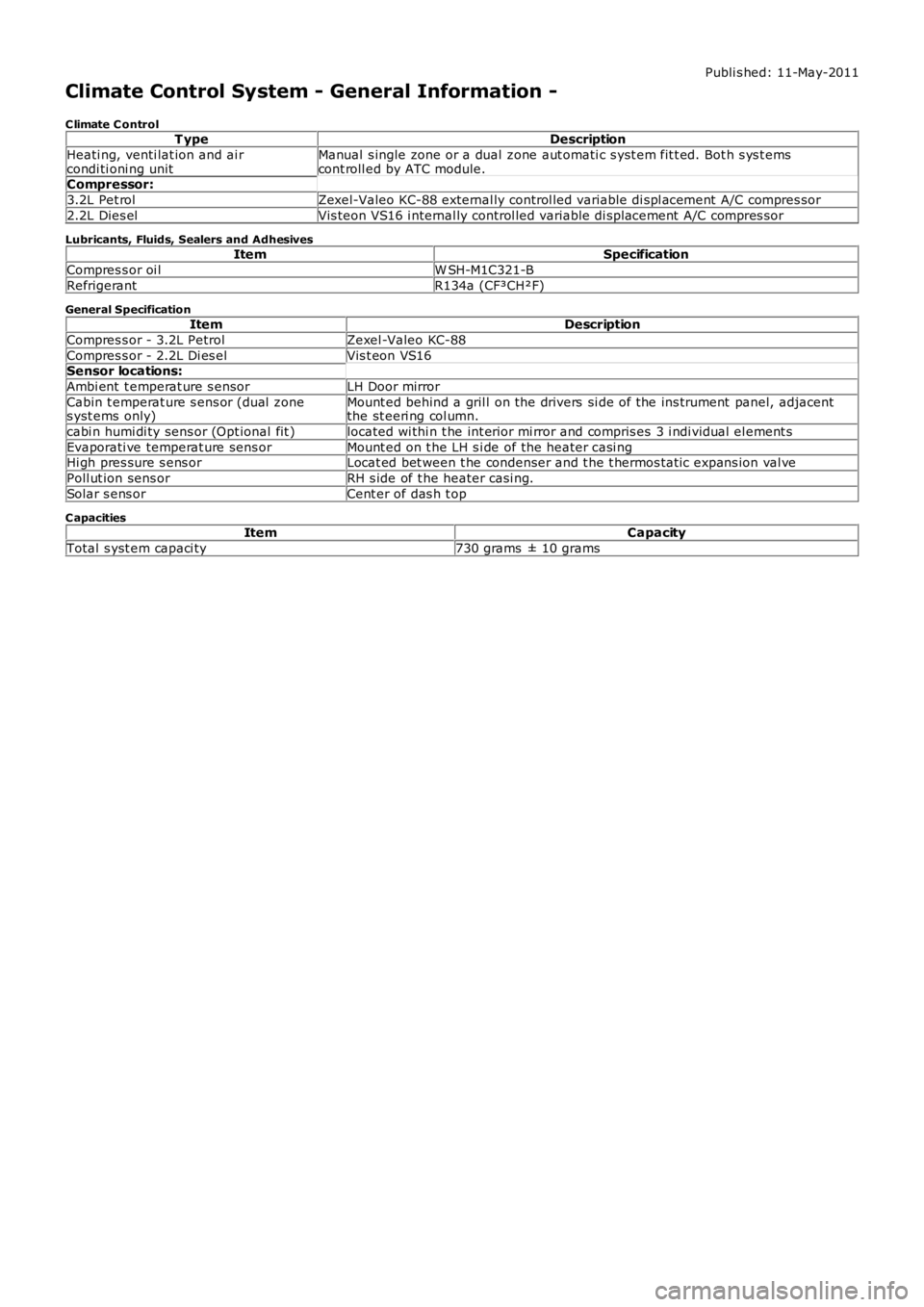
Publi s hed: 11-May-2011
Climate Control System - General Information -
C limate C ontrolT ypeDescription
Heati ng, venti lat ion and ai rcondi ti oni ng unitManual s ingle zone or a dual zone aut omati c s yst em fit t ed. Bot h s ys t emscont roll ed by ATC module.Compressor:
3.2L Pet rolZexel-Valeo KC-88 external ly control led variable di spl acement A/C compres sor
2.2L Dies elVis teon VS16 i nternal ly control led variable di spl acement A/C compres sor
Lubricants, Fluids, Sealers and AdhesivesItemSpecification
Compres s or oi lW SH-M1C321-B
RefrigerantR134a (CF³CH²F)
General SpecificationItemDescription
Compres s or - 3.2L PetrolZexel -Valeo KC-88
Compres s or - 2.2L Di es elVis t eon VS16Sensor locations:
Ambi ent t emperat ure s ensorLH Door mirror
Cabin t emperat ure s ens or (dual zones yst ems only)Mount ed behind a gril l on the drivers si de of the ins trument panel, adjacentthe st eeri ng col umn.
cabi n humi di ty sens or (Opt ional fit )located wi thi n t he int erior mi rror and compris es 3 i ndi vidual el ement s
Evaporati ve temperat ure sens orMount ed on t he LH s i de of the heater casi ngHi gh pres sure s ens orLocat ed bet ween t he condenser and t he t hermos tat ic expans ion val ve
Poll ut ion sens orRH s ide of t he heater casi ng.
Solar s ens orCent er of das h t op
C apacitiesItemCapacity
Total s yst em capaci ty730 grams ± 10 grams
Page 1629 of 3229
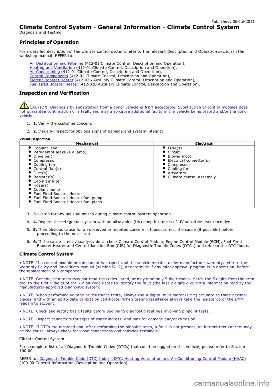
Publi shed: 06-Jul-2011
Climate Control System - General Information - Climate Control System
Diagnosi s and Tes ti ng
Principles of Operation
For a detail ed descripti on of the cl imat e cont rol s yst em, refer to the relevant Des cri pti on and Operati on s ect ion i n t heworks hop manual . REFER to:
Air Dis t ri but ion and Fi lt ering (412-01 Cl imat e Control, Des cript ion and Operat ion),Heat ing and Vent il at ion (412-01 Cl imat e Control, Des cript ion and Operat ion),Air Condi ti oning (412-01 Cli mate Cont rol , Des cri pti on and Operati on),Cont rol Component s (412-01 Cli mate Cont rol , Des cri pti on and Operati on),Elect ric Boost er Heater (412-02B Auxi liary Cli mate Cont rol , Descri pti on and Operat ion),Fuel Fired Boos t er Heat er (412-02B Auxil iary Cli mate Cont rol, Des cri pt ion and Operati on).
Inspection and Verification
CAUTION: Di agnos is by s ubs ti tut ion from a donor vehicle is NO T acceptabl e. Subs ti tut ion of cont rol modules doesnot guarant ee confirmat ion of a faul t, and may als o caus e addit ional fault s i n t he vehi cl e being t est ed and/or t he donorvehi cl e.
1. Verify t he cus t omer concern.1.
2. Vis ually ins pect for obvious s igns of damage and s ys t em i ntegri ty.2.
Visual InspectionMechanicalElectrical
Coolant levelRefrigerant l eaks (UV l amp)Drive beltCompres s orCooli ng fanControl flap(s)Duct(s )Regis ter(s )Cabin ai r fi lt erHos e(s )Coolant pumpFuel Fi red Boos ter HeaterFuel Fi red Boos ter Heater fuel pumpFuel Fi red Boos ter Heater fuel pipes
Fus e(s)Circui tBlower mot orElectrical connect or(s)Compres s orCool ing fanAct uatorsCli mate cont rol ass embly
3. Lis ten for any unus ual noi ses during cli mate cont rol s ys t em operat ion.3.
4. Ins pect t he refri gerant s ys t em wi th an ult raviolet (UV) lamp for t races of UV s ens i ti ve leak t race dye.4.
5. If an obvious cause for an obs erved or report ed concern is found, correct t he caus e (if pos s ible) beforeproceeding t o t he next s t ep5.
6. If t he caus e is not vis ually evi dent , check Cli mate Cont rol Module, Engi ne Control Module (ECM), Fuel FiredBoos ter Heater and Central Juncti on Box (CJB) for Di agnos ti c Trouble Codes (DTCs ) and refer to the DTC Index.6.
Climate Control System
• NOTE: If a cont rol module or component i s s uspect and the vehicl e remai ns under manufacturer warrant y, refer t o t heW arranty Pol icy and Procedures manual (s ect ion B1.2), or determine i f any pri or approval program is i n operat ion, beforet he replacement of a component.
• NOTE: Generic scan t ool s may not read the codes li st ed, or may read only 5-digi t codes . Match t he 5 digi ts from t he s cant ool t o t he fi rs t 5 di gi ts of the 7-digit code li s ted t o i dent ify the fault (the last 2 digi ts gi ve ext ra informati on read by themanufacturer-approved di agnos ti c s ys t em).
• NOTE: W hen performing volt age or res is t ance t est s , always use a digi tal mult imeter (DMM) accurat e t o t hree deci malplaces, and wi th an up-t o-date cal ibrat ion cert ificate. W hen tes ti ng res is t ance al ways take t he res is t ance of t he DMMleads i nt o account .
• NOTE: Check and recti fy bas ic faul ts before beginni ng diagnos t ic rout ines i nvol vi ng pinpoint t es t s.
• NOTE: Ins pect connect ors for s igns of water ingres s , and pins for damage and/or corros ion.
• NOTE: If DTCs are recorded and, aft er performi ng the pi npoi nt tes ts , a fault is not present , an int ermi tt ent concern maybe t he caus e. Always check for loose connect ions and corroded terminals .
Cli mate Cont rol Syst em
For a compl ete lis t of all Di agnos ti c Trouble Codes (DTCs) t hat could be logged on this vehicle, pleas e refer to Sect ion100-00.
REFER to: Di agnos ti c Trouble Code (DTC) Index - DTC: Heati ng Vent il ati on and Air Condit ioning Control Modul e (HVAC)(100-00 General Informati on, Des cri pti on and Operati on).
Page 1632 of 3229
Publi s hed: 11-May-2011
Climate Control -
Torque SpecificationsDescriptionNmlb-ft
A/C compres sor refridgerant li ne connect ions2418
A/C condens er refridgerant li ne connecti ons107Compres s or lower s upport bracket - 3.2 Pet rol2518
Compressor upper support bracket - 3.2 Petrol:
M104533M82518
M6107
Compres s or mount ing bol ts - Al l engi nes25Condens er core bolt s107
Heater core and evaporat or core hous ing bol ts76
Heater housi ng t o bulkhead Torx bolt s76Pres s ure t rans ducer86
Thermos t at ic expansi on valve bolt s43
Thermos t at ic expansi on valve nut97
Page 1634 of 3229
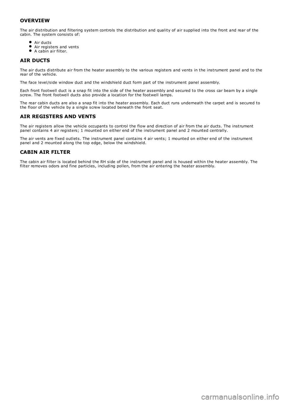
OVERVIEW
The air dis t ri but ion and fil tering s ys tem cont rols the di st ributi on and qual it y of air s uppl ied i nto t he front and rear of t hecabi n. The sys tem cons is t s of:
Air ductsAir regi s ters and vent sA cabin ai r fi lt er.
AIR DUCTS
The air ducts di st ri bute ai r from t he heater as sembl y to the various regi st ers and vents in t he i ns t rument panel and t o t herear of t he vehi cl e.
The face l evel /s ide window duct and t he wi nds hiel d duct form part of t he ins trument panel as sembl y.
Each front footwell duct is a s nap fit into the s i de of the heater as s embly and s ecured t o the cross car beam by a s ingles crew. The front footwel l ducts als o provide a locati on for t he foot well lamps .
The rear cabi n ducts are als o a snap fit i nto the heater as s embly. Each duct runs underneath t he carpet and is secured t ot he fl oor of t he vehi cl e by a si ngl e s crew l ocat ed beneat h t he front seat .
AIR REGISTERS AND VENTS
The air regi s ters allow the vehicle occupant s t o cont rol t he fl ow and di recti on of ai r from t he air ducts . The ins t rumentpanel contains 4 air regi st ers ; 1 mount ed on eit her end of t he i ns t rument panel and 2 mount ed central ly.
The air vents are fixed outl et s . The ins trument panel cont ains 4 ai r vent s ; 1 mounted on ei ther end of t he ins trumentpanel and 2 mount ed along t he t op edge, below the wi ndshi el d.
CABIN AIR FILTER
The cabi n air fil ter is locat ed behind t he RH s i de of the i nst rument panel and is housed wit hin t he heater as sembl y. Thefi lt er removes odors and fine part icl es , i ncludi ng pol len, from t he air ent ering the heater as s embly.
Page 1635 of 3229
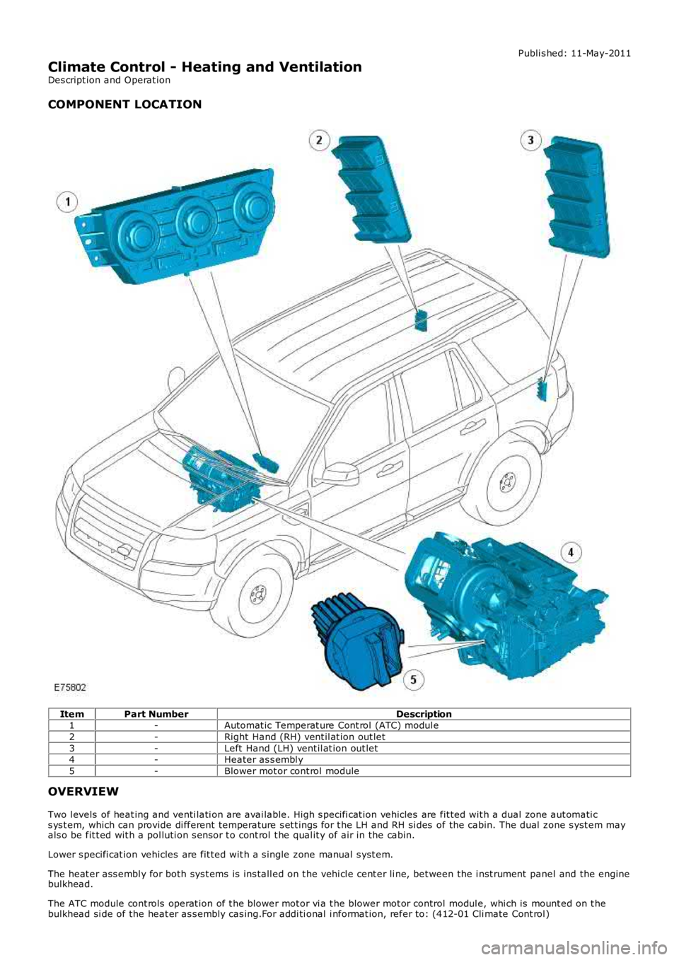
Publi s hed: 11-May-2011
Climate Control - Heating and Ventilation
Des cript ion and Operat ion
COMPONENT LOCATION
ItemPart NumberDescription1-Automat ic Temperat ure Cont rol (ATC) modul e
2-Right Hand (RH) vent il at ion out let
3-Left Hand (LH) vent il at ion out let4-Heater as s embl y
5-Blower mot or cont rol module
OVERVIEW
Two l evels of heat ing and venti lati on are avai lable. High s pecifi cat ion vehicles are fit ted wit h a dual zone aut omati cs ys t em, which can provide di fferent temperature s et t ings for t he LH and RH si des of the cabin. The dual zone s yst em mayals o be fit t ed wit h a pol luti on s ens or t o cont rol t he qual it y of air in the cabin.
Lower s pecifi cat ion vehicles are fit ted wit h a s ingle zone manual s yst em.
The heat er ass embl y for both sys t ems is ins tall ed on t he vehi cl e cent er li ne, bet ween the i nst rument panel and the enginebulkhead.
The ATC module cont rols operat ion of t he blower mot or vi a t he blower mot or control modul e, whi ch is mount ed on t hebulkhead si de of the heat er as s embly cas ing.For addi ti onal i nformat ion, refer to: (412-01 Cli mate Cont rol )
Page 1636 of 3229
Air Dis t ri but ion and Fi lt ering (Des cript ion and Operat ion),Air Condi ti oning (Descri pti on and Operat ion),Cont rol Component s (Descri pti on and Operat ion).
Some vehicles may al s o be fit ted wi th an auxi li ary heater. For addit ional i nformati on, refer t o: (412-02B Auxil iary Cl imat eControl )
Elect ric Boost er Heater (Des cri pti on and Operati on),Fuel Fired Boos t er Heat er (Des cript ion and O perati on).
AUTOMATIC TEMPERATURE CONTROL MODULE
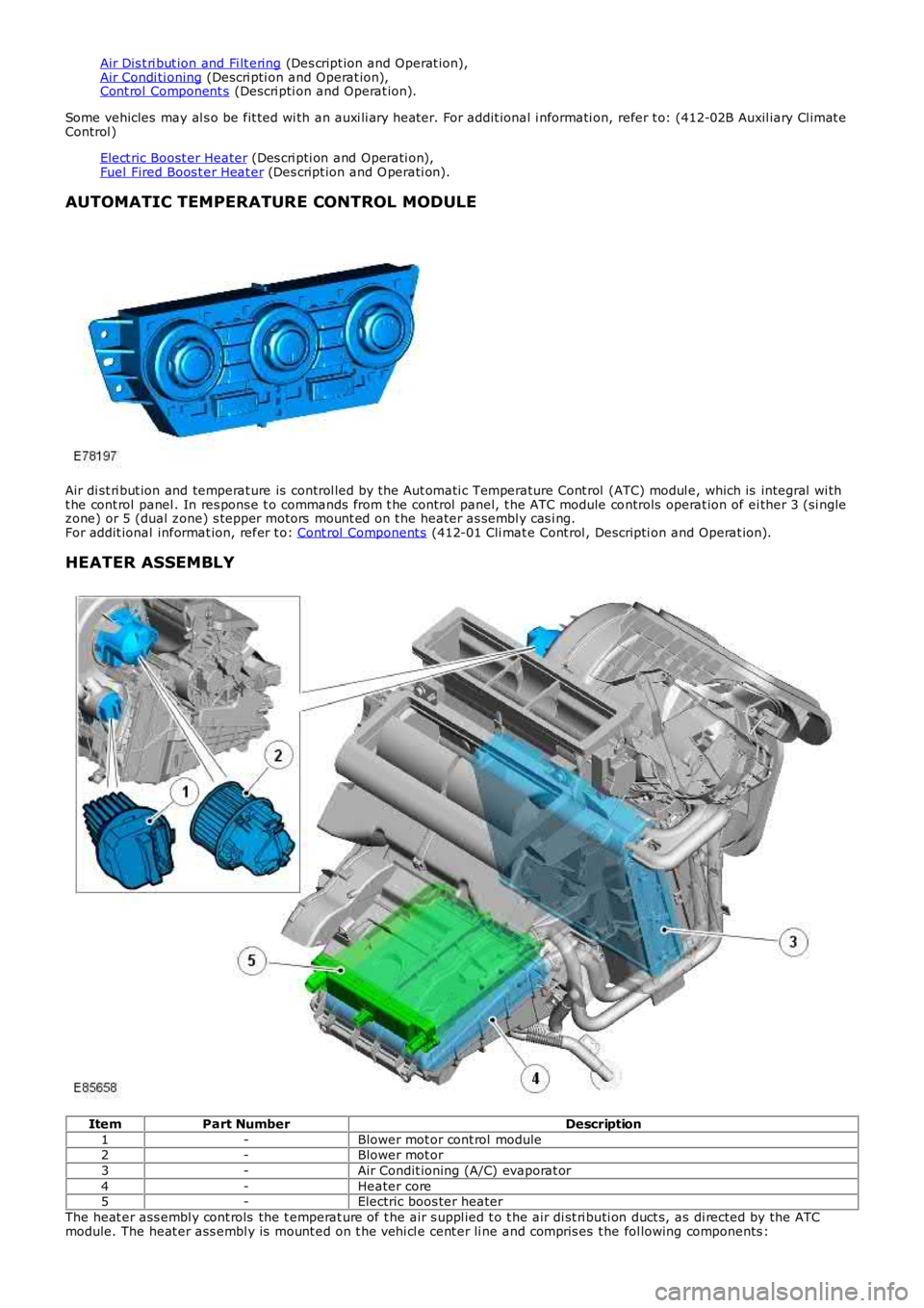
Air di st ri but ion and temperat ure is control led by the Aut omati c Temperature Cont rol (ATC) modul e, which is integral wi tht he cont rol panel . In res pons e t o commands from t he control panel, t he ATC module controls operat ion of ei ther 3 (si nglezone) or 5 (dual zone) s tepper motors mount ed on t he heater as sembl y cas i ng.For addit ional informat ion, refer t o: Cont rol Component s (412-01 Cli mat e Cont rol , Descripti on and Operat ion).
HEATER ASSEMBLY
ItemPart NumberDescription
1-Blower mot or cont rol module2-Blower mot or
3-Air Condit ioning (A/C) evaporat or
4-Heater core5-Electric boos ter heater
The heat er ass embl y cont rols the t emperat ure of t he air s uppl ied t o t he air di st ri buti on duct s, as di rected by the ATCmodule. The heat er ass embl y is mount ed on t he vehi cl e cent er li ne and compris es t he fol lowing components :