2006 LAND ROVER FRELANDER 2 heater
[x] Cancel search: heaterPage 1770 of 3229
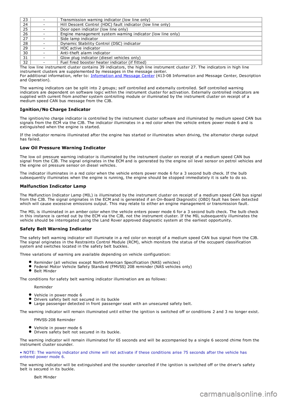
23-Transmis s ion warni ng indi cat or (low li ne only)
24-Hil l Des cent Cont rol (HDC) fault i ndi cat or (l ow li ne only)
25-Door open i ndi cat or (l ow li ne only)26-Engi ne management s yst em warning i ndicat or (l ow l ine only)
27-Side l amp indicat or
28-Dynami c Stabil it y Control (DSC) indicat or29-HDC acti ve indicator
30-Ant i-t heft alarm i ndi cat or
31-Glow pl ug indicat or (dies el vehicles onl y)32-Fuel fired boos ter heater i ndi cat or (i f fi tt ed)
The low li ne ins trument cl ust er cont ains 39 i ndi cat ors , the hi gh li ne ins t rument clus ter 27. The indicators in hi gh li neins t rument clus ters are s upplemented by mess ages in the mess age cent er.For addit ional informat ion, refer t o: Informat ion and Mes s age Cent er (413-08 Informat ion and Mes s age Cent er, Des cript ionand Operat ion).
The warni ng indicators can be s plit i nto 2 groups ; sel f cont roll ed and ext ernall y cont rol led. Self cont rol led warni ngindicat ors are dependent on software l ogi c wit hin t he i ns t rument clus ter for act ivati on. External ly controll ed indicators ares uppl ied wi th current from anot her s yst em cont roll ing module or ill uminat ed by the ins trument cl us t er on receipt of amedium s peed CAN bus mes sage from the CJB.
Ignition/No Charge Indicator
The ignit ion/no charge indicator i s cont rol led by t he ins t rument clus ter s oft ware and i ll uminated by medium speed CAN buss ignals from the ECM via t he CJB. The indicator il lumi nat es i n a red col or when the vehicle ent ers power mode 6 and isexti nguis hed when t he engine i s s tart ed.
If the i ndi cat or remai ns ill uminat ed aft er the engine has s t art ed or ill uminat es when drivi ng, t he alt ernator charge out puthas fai led.
Low Oil Pressure Warning Indicator
The low oil pres s ure warning i ndi cat or is i lluminated by t he i ns t rument clus ter on recei pt of a medium speed CAN buss ignal from t he CJB. The s ignal ori gi nates i n t he ECM and is generat ed by t he engi ne oil l evel s ens or on petrol vehicl es andt he engi ne oil pres s ure s ensor on di esel vehi cles .
The indicat or i ll uminates i n a red color when t he vehi cl e enters power mode 6 for a 3 s econd bulb check. If t he bul bs ubs equent ly ill uminat es when the engine is runni ng, t he engine s houl d be s t opped i mmediat ely i t is s afe to do s o.
Malfunction Indicator Lamp
The Malfunct ion Indicat or Lamp (MIL) i s il lumi nat ed by t he ins trument cl ust er on receipt of a medi um s peed CAN bus s ignalfrom the CJB. The si gnal originat es in t he ECM and i s generated if an On-Board Diagnos ti c (OBD) fault has been det ectedwhich wi ll caus e excess i ve emis s ions output. Thi s may rel ate to ei ther an engine management or trans mi ss i on fault .
The MIL is ill uminat ed in an amber color when t he vehi cl e enters power mode 6 for a 3 s econd bul b check. The bul b checkin thi s ins tance is carri ed out by the ECM vi a t he CJB, not t he ins trument cl ust er. If t he MIL subs equent ly i lluminates t hevehi cl e s houl d be i nterrogated us ing t he Land Rover approved diagnost ic sys tem at the earli es t opport uni ty.
Safety Belt Warning Indicator
The s afety bel t warni ng indicator wi ll il lumi nat e i n a red color on receipt of a medi um s peed CAN bus s ignal from t he CJB.The s ignal origi nat es in the Res traint s Cont rol Module (RCM), which monit ors the s t at us of t he occupant clas s ificati ons ys t em and s wi tches located i n t he s afety bel t buckles .
Three vari ati ons of warning are avai lable depending on vehicle confi gurati on:
Reminder (al l vehicl es except Nort h Ameri can Specificati on (NAS) vehicles )Federal Mot or Vehi cl e Safet y Standard (FMVSS) 208 remi nder (NAS vehi cles only)Belt Mi nder
The condi ti ons for s afety bel t warning indicator il lumi nat ion are as follows :
Reminder
Vehicle i n power mode 6Dri vers s afet y belt not s ecured in i ts buckleLarge pas senger det ect ed i n front pas s enger s eat wit h an uns ecured safety bel t.
The warni ng indicator wi ll remai n i lluminated unt il eit her t he i gni ti on is swi tched off or condi ti ons 2 and 3 no longer exis t .
FMVSS-208 Reminder
Vehicle i n power mode 6Dri vers s afet y belt not s ecured in i ts buckle.
The warni ng indicator wi ll remai n i lluminated for 65 s econds and wil l be accompanied by a si ngl e 6 second chi me from theins t rument clus ter s ounder.
• NOTE: The warni ng indicator and chime wil l not acti vat e i f thes e condi ti ons aris e 75 seconds aft er t he vehicle hasentered power mode 6.
The warni ng indicator wi ll be exti ngui shed and t he s ounder cancell ed if t he i gni ti on is s wi tched off or t he dri ver's s afet ybelt i s s ecured in i ts buckle.
Belt Mi nder
Page 1794 of 3229
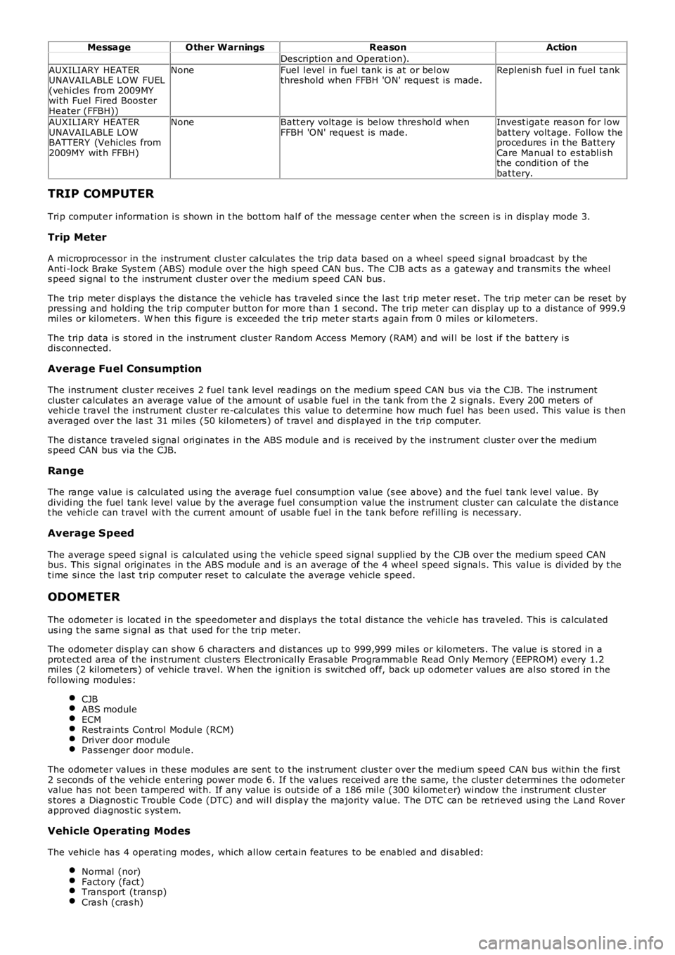
MessageO ther WarningsReasonAction
Descripti on and Operat ion).
AUXILIARY HEATERUNAVAILABLE LOW FUEL(vehi cl es from 2009MYwi th Fuel Fired Boos t erHeater (FFBH))
NoneFuel l evel in fuel tank i s at or bel owthreshold when FFBH 'ON' reques t is made.Repl eni sh fuel in fuel tank
AUXILIARY HEATERUNAVAILABLE LOWBATTERY (Vehicles from2009MY wit h FFBH)
NoneBatt ery volt age is bel ow t hres hol d whenFFBH 'ON' reques t is made.Invest igat e reas on for l owbat tery volt age. Follow theprocedures i n t he Batt eryCare Manual t o es t abl is hthe condi ti on of thebat tery.
TRIP COMPUTER
Tri p comput er informat ion i s s hown in t he bott om hal f of the mes s age cent er when the s creen i s in dis play mode 3.
Trip Meter
A microprocess or in the ins trument cl us t er calculat es the trip dat a based on a wheel speed s ignal broadcas t by t heAnti -l ock Brake Sys t em (ABS) modul e over the hi gh speed CAN bus . The CJB act s as a gat eway and t ransmit s t he wheels peed si gnal t o t he ins trument cl ust er over t he medium s peed CAN bus .
The t rip meter di spl ays t he dis t ance t he vehicle has t raveled s i nce t he l as t t ri p met er res et . The t ri p met er can be reset bypres s ing and holdi ng the t rip computer butt on for more t han 1 s econd. The t ri p met er can dis play up to a dis t ance of 999.9mi les or kil omet ers . W hen this fi gure is exceeded the t ri p met er st art s again from 0 miles or ki lometers .
The t rip dat a i s s tored in the i nst rument clus t er Random Acces s Memory (RAM) and will be los t if t he batt ery i sdis connected.
Average Fuel Consumption
The ins t rument clus ter receives 2 fuel t ank level readings on t he medium s peed CAN bus vi a t he CJB. The i nst rumentclus ter calcul ates an average value of t he amount of usable fuel in the t ank from t he 2 s i gnal s. Every 200 meters ofvehi cl e t ravel the i nst rument clus t er re-calculat es this val ue to det ermine how much fuel has been us ed. Thi s value i s thenaveraged over t he las t 31 mi les (50 kil ometers ) of t ravel and di s pl ayed in t he t ri p comput er.
The dis t ance t raveled s ignal ori gi nates i n t he ABS module and i s received by t he inst rument clus ter over t he medi ums peed CAN bus via t he CJB.
Range
The range value i s calculated us i ng the average fuel cons umpt ion val ue (s ee above) and t he fuel t ank level val ue. Bydividi ng the fuel tank l evel val ue by t he average fuel cons umpti on value t he ins t rument clus ter can cal cul at e t he dis t ancet he vehi cl e can travel wi th the current amount of us abl e fuel i n t he tank before refil li ng is necess ary.
Average Speed
The average s peed s i gnal is cal cul at ed us ing t he vehi cle s peed s ignal s uppli ed by the CJB over the medium speed CANbus. This si gnal originat es in t he ABS module and is an average of t he 4 wheel s peed si gnal s. This val ue is di vided by t het ime si nce the l ast t ri p computer res et t o cal cul ate the average vehicle s peed.
ODOMETER
The odometer is locat ed i n the speedometer and dis plays t he tot al di s tance the vehicl e has travel ed. This is calculat edus ing t he s ame s ignal as that us ed for t he trip meter.
The odometer dis play can s how 6 characters and dis t ances up t o 999,999 mi les or kil ometers . The value i s s tored in aprot ect ed area of t he ins t rument clus ters Electroni cal ly Eras able Programmabl e Read Only Memory (EEPROM) every 1.2mi les (2 kil ometers ) of vehicle t ravel. W hen the i gnit ion i s s wit ched off, back up odomet er val ues are al so s tored in t hefol lowing modul es:
CJBABS moduleECMRest rai nts Cont rol Modul e (RCM)Dri ver door modulePass enger door module.
The odometer values in thes e modules are s ent t o t he ins t rument clus ter over t he medi um s peed CAN bus wit hin the firs t2 s econds of t he vehi cl e entering power mode 6. If the values received are t he s ame, t he clus ter det ermi nes t he odometervalue has not been tampered wit h. If any value i s outs ide of a 186 mil e (300 ki lometer) wi ndow the i nst rument clus t ers tores a Diagnos ti c Trouble Code (DTC) and wil l di spl ay the majori ty val ue. The DTC can be ret rieved us ing t he Land Roverapproved diagnos t ic s yst em.
Vehicle Operating Modes
The vehi cl e has 4 operat ing modes , which al low cert ain features to be enabl ed and dis abl ed:
Normal (nor)Fact ory (fact )Trans port (trans p)Cras h (cras h)
Page 1834 of 3229
NameItemNumberVehicleDescription
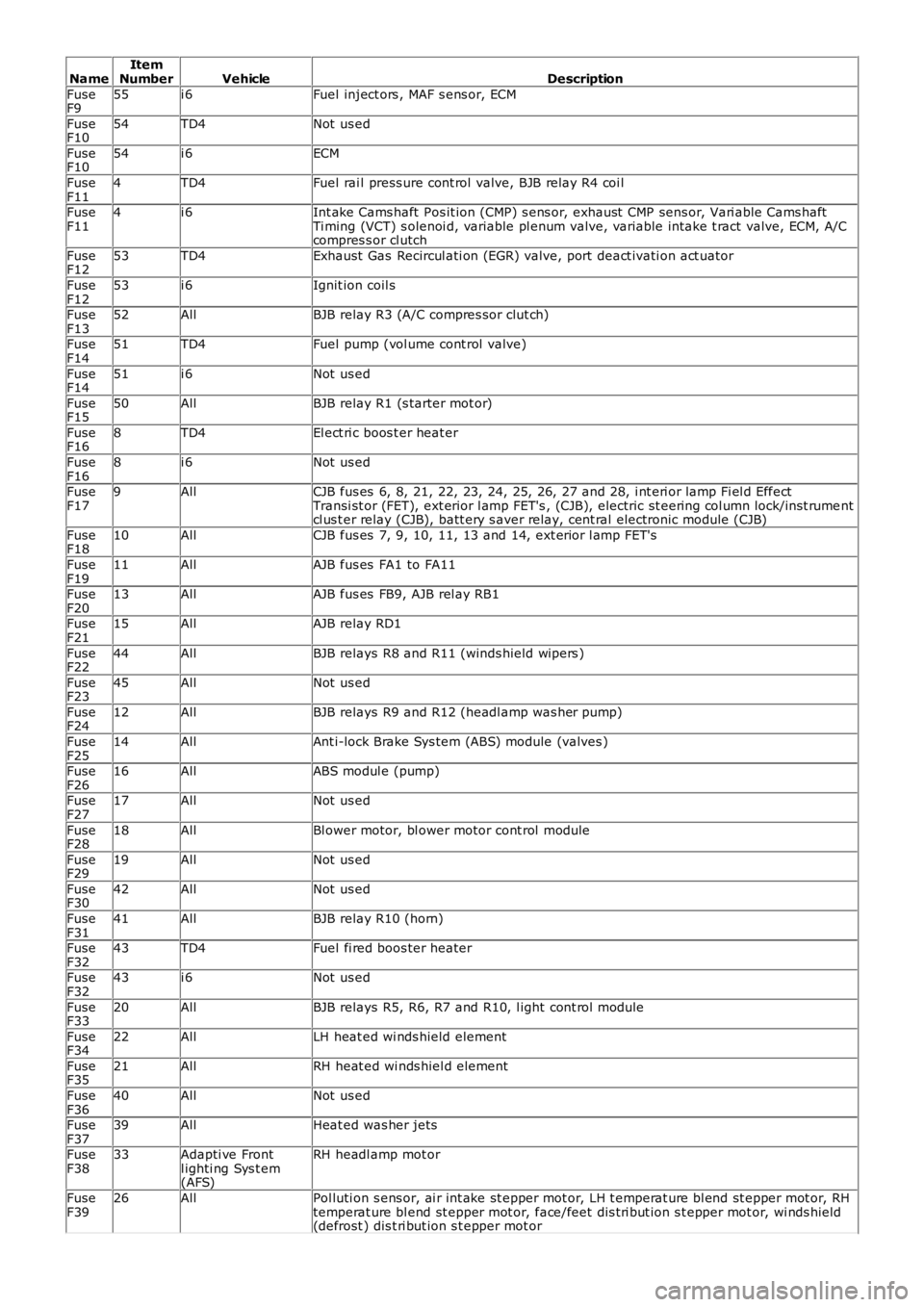
FuseF955i 6Fuel inject ors , MAF s ens or, ECM
FuseF1054TD4Not us ed
FuseF1054i 6ECM
FuseF114TD4Fuel rai l press ure cont rol valve, BJB relay R4 coi l
FuseF114i 6Int ake Cams haft Pos it ion (CMP) s ens or, exhaust CMP sens or, Vari able Cams haftTi ming (VCT) s olenoi d, variable pl enum valve, variable intake t ract valve, ECM, A/Ccompres s or cl utch
FuseF1253TD4Exhaust Gas Recircul ati on (EGR) valve, port deact ivati on act uator
FuseF1253i 6Ignit ion coil s
FuseF1352AllBJB relay R3 (A/C compres sor clut ch)
FuseF1451TD4Fuel pump (vol ume cont rol valve)
FuseF1451i 6Not us ed
FuseF1550AllBJB relay R1 (s tarter mot or)
FuseF168TD4El ect ri c boos t er heat er
FuseF168i 6Not us ed
FuseF179AllCJB fus es 6, 8, 21, 22, 23, 24, 25, 26, 27 and 28, i nt eri or lamp Fi el d EffectTransi st or (FET), ext erior l amp FET's , (CJB), electric st eering col umn lock/i ns t rumentcl us t er relay (CJB), batt ery s aver relay, cent ral electronic module (CJB)
FuseF1810AllCJB fus es 7, 9, 10, 11, 13 and 14, ext erior l amp FET's
FuseF1911AllAJB fus es FA1 to FA11
FuseF2013AllAJB fus es FB9, AJB rel ay RB1
FuseF2115AllAJB relay RD1
FuseF2244AllBJB relays R8 and R11 (winds hield wipers )
FuseF2345AllNot us ed
FuseF2412AllBJB relays R9 and R12 (headl amp was her pump)
FuseF2514AllAnt i-lock Brake Sys tem (ABS) module (valves )
FuseF2616AllABS modul e (pump)
FuseF2717AllNot us ed
FuseF2818AllBl ower motor, bl ower motor cont rol module
FuseF2919AllNot us ed
FuseF3042AllNot us ed
FuseF3141AllBJB relay R10 (horn)
FuseF3243TD4Fuel fi red boos ter heater
FuseF3243i 6Not us ed
FuseF3320AllBJB relays R5, R6, R7 and R10, l ight cont rol module
FuseF3422AllLH heat ed wi nds hield element
FuseF3521AllRH heat ed wi nds hiel d element
FuseF3640AllNot us ed
FuseF3739AllHeat ed was her jets
FuseF3833Adapti ve Frontl ighti ng Sys t em(AFS)
RH headl amp mot or
FuseF3926AllPol luti on s ens or, ai r int ake st epper mot or, LH t emperat ure bl end st epper mot or, RHtemperat ure bl end st epper mot or, face/feet dis t ri but ion s t epper mot or, wi nds hield(defrost ) dis t ri but ion s t epper mot or
Page 1843 of 3229
Publi s hed: 11-May-2011
Generator and Regulator - GeneratorTD4 2.2L Diesel
Des cript ion and Operat ion
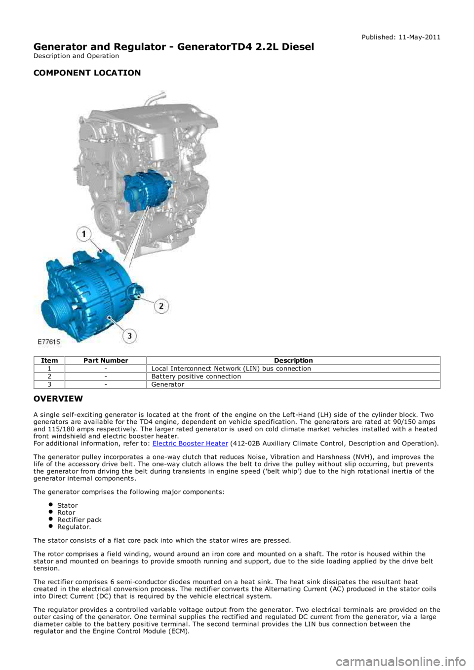
COMPONENT LOCATION
ItemPart NumberDescription
1-Local Interconnect Net work (LIN) bus connect ion2-Bat tery pos i ti ve connect ion
3-Generat or
OVERVIEW
A s i ngl e s elf-exci ti ng generator is locat ed at t he front of t he engine on t he Left -Hand (LH) s ide of t he cyl inder bl ock. Twogenerators are avail abl e for t he TD4 engine, dependent on vehi cl e s peci fi cat ion. The generat ors are rated at 90/150 ampsand 115/180 amps respecti vel y. The l arger rat ed generator is us ed on cold cl imat e market vehicles ins tall ed wit h a heat edfront winds hi eld and el ect ri c boos t er heat er.For addit ional informat ion, refer t o: Electric Boos ter Heater (412-02B Auxi li ary Cl imat e Control , Descripti on and Operat ion).
The generator pull ey incorporates a one-way clut ch that reduces Nois e, Vi brat ion and Harshnes s (NVH), and improves theli fe of t he acces s ory drive belt . The one-way clut ch al lows t he belt t o drive t he pul ley wi thout s li p occurring, but prevent st he generat or from driving t he belt during t rans ients in engine s peed ('belt whip') due to the hi gh rot at ional inert ia of thegenerator int ernal components .
The generator compri ses t he fol lowi ng major component s:
Stat orRotorRect ifier packRegul ator.
The s tat or cons is ts of a fl at core pack into which t he s tat or wi res are pres s ed.
The rot or compris es a fiel d winding, wound around an i ron core and mounted on a s haft. The rotor is hous ed wi thin thes tat or and mount ed on beari ngs to provi de s mooth running and s upport, due t o t he s ide l oadi ng appl ied by t he dri ve beltt ens ion.
The rect ifi er compris es 6 s emi -conductor di odes mount ed on a heat s ink. The heat s ink di ss i pat es t he res ult ant heatcreated in t he electrical convers ion proces s . The recti fi er converts the Al ternat ing Current (AC) produced i n the st ator coil sint o Di rect Current (DC) that is required by the vehicl e electrical sys tem.
The regulat or provides a control led variable volt age output from the generat or. Two electrical terminals are provi ded on theouter casi ng of the generat or. One t ermi nal s uppli es the rect ified and regul ated DC current from the generat or, via a largediamet er cable to the bat tery pos i ti ve terminal. The s econd terminal provides t he LIN bus connect ion bet ween theregulat or and the Engine Cont rol Modul e (ECM).
Page 1972 of 3229
Publi s hed: 11-May-2011
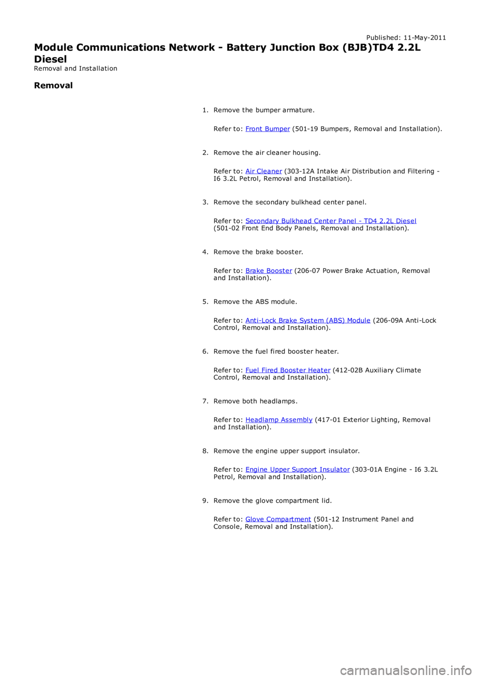
Module Communications Network - Battery Junction Box (BJB)TD4 2.2L
Diesel
Removal and Inst all ati on
Removal
Remove t he bumper armature.
Refer t o: Front Bumper (501-19 Bumpers , Removal and Ins tall ati on).
1.
Remove t he air cleaner hous ing.
Refer t o: Air Cleaner (303-12A Intake Ai r Dis tribut ion and Fil tering -I6 3.2L Pet rol, Removal and Ins t al lat ion).
2.
Remove t he s econdary bulkhead cent er panel.
Refer t o: Secondary Bulkhead Cent er Panel - TD4 2.2L Dies el(501-02 Front End Body Panel s, Removal and Ins tal lati on).
3.
Remove t he brake boost er.
Refer t o: Brake Boost er (206-07 Power Brake Act uat ion, Removaland Inst all at ion).
4.
Remove t he ABS module.
Refer t o: Ant i-Lock Brake Sys t em (ABS) Modul e (206-09A Anti -LockControl, Removal and Ins tall ati on).
5.
Remove t he fuel fi red boos ter heater.
Refer t o: Fuel Fired Boos t er Heat er (412-02B Auxil iary Cli mateControl, Removal and Ins tall ati on).
6.
Remove both headlamps .
Refer t o: Headl amp As sembl y (417-01 Ext eri or Li ght ing, Removaland Inst all at ion).
7.
Remove t he engi ne upper s upport ins ulat or.
Refer t o: Engi ne Upper Support Ins ulat or (303-01A Engine - I6 3.2LPetrol, Removal and Ins tall ati on).
8.
Remove t he glove compartment l id.
Refer t o: Glove Compart ment (501-12 Ins trument Panel andConsol e, Removal and Ins t al lat ion).
9.
Page 1991 of 3229
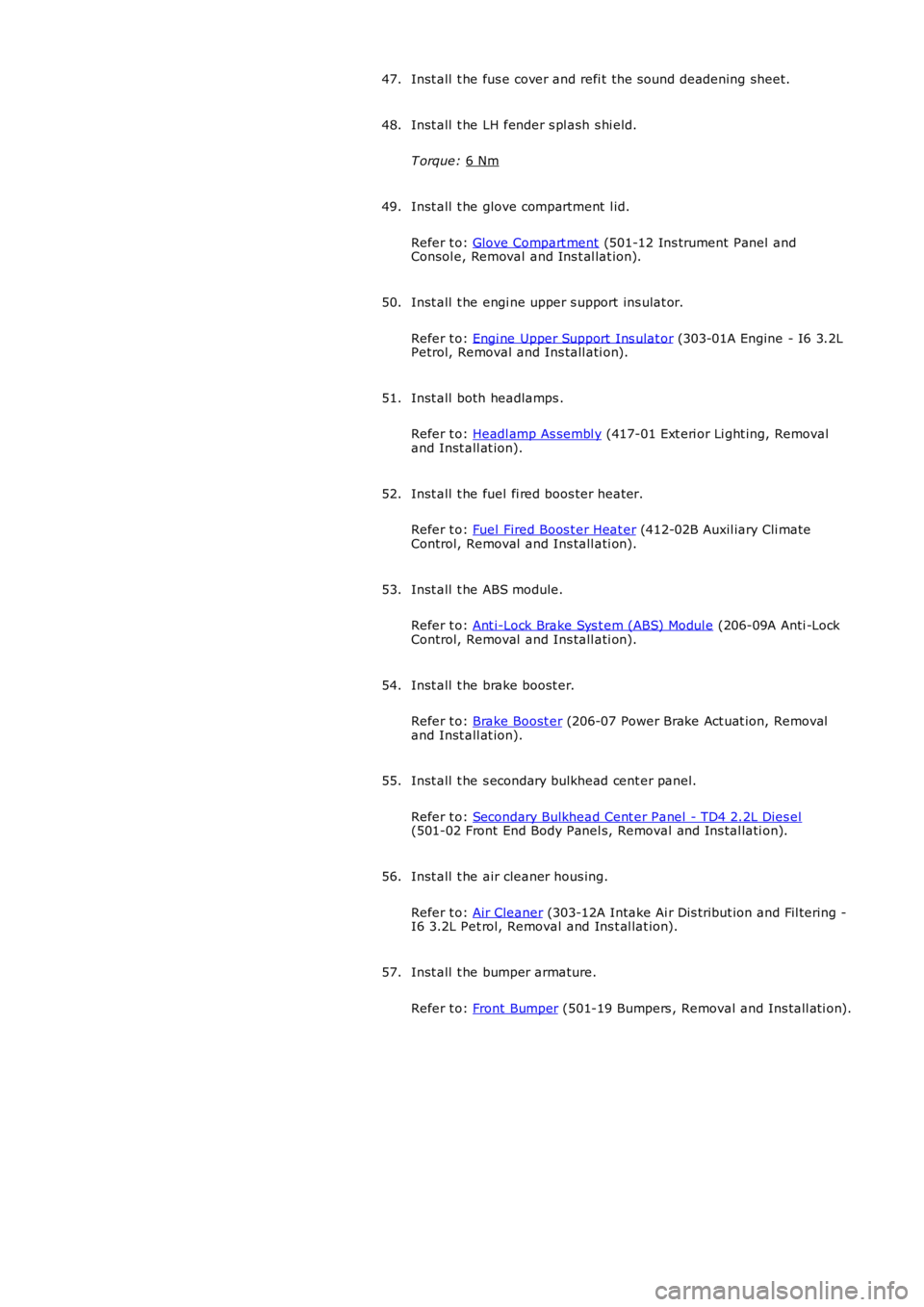
Inst all t he fus e cover and refi t the s ound deadening sheet.
47.
Inst all t he LH fender s pl ash s hi eld.
T orque: 6 Nm 48.
Inst all t he glove compartment l id.
Refer t o: Glove Compart ment (501-12 Ins trument Panel and
Consol e, Removal and Ins t al lat ion).
49.
Inst all t he engi ne upper s upport ins ulat or.
Refer t o: Engi ne Upper Support Ins ulat or (303-01A Engine - I6 3.2L
Petrol, Removal and Ins tall ati on).
50.
Inst all both headlamps .
Refer t o: Headl amp As sembl y (417-01 Ext eri or Li ght ing, Removal
and Inst all at ion).
51.
Inst all t he fuel fi red boos ter heater.
Refer t o: Fuel Fired Boos t er Heat er (412-02B Auxil iary Cli mate
Control, Removal and Ins tall ati on).
52.
Inst all t he ABS module.
Refer t o: Ant i-Lock Brake Sys t em (ABS) Modul e (206-09A Anti -Lock
Control, Removal and Ins tall ati on).
53.
Inst all t he brake boost er.
Refer t o: Brake Boost er (206-07 Power Brake Act uat ion, Removal
and Inst all at ion).
54.
Inst all t he s econdary bulkhead cent er panel.
Refer t o: Secondary Bulkhead Cent er Panel - TD4 2.2L Dies el (501-02 Front End Body Panel s, Removal and Ins tal lati on).
55.
Inst all t he air cleaner hous ing.
Refer t o: Air Cleaner (303-12A Intake Ai r Dis tribut ion and Fil tering -
I6 3.2L Pet rol, Removal and Ins t al lat ion).
56.
Inst all t he bumper armature.
Refer t o: Front Bumper (501-19 Bumpers , Removal and Ins tall ati on).
57.
Page 2072 of 3229
3-Touch Screen Dis play (TAD)
4-Integrat ed Head Unit (IHU) - Hi-Li ne
5-Bl uet ooth phone module6-Ampl ifier/t uner
7-Di git al Audio Broadcas t (DAB) recei ver
8-Navigat ion computer
OVERVIEW
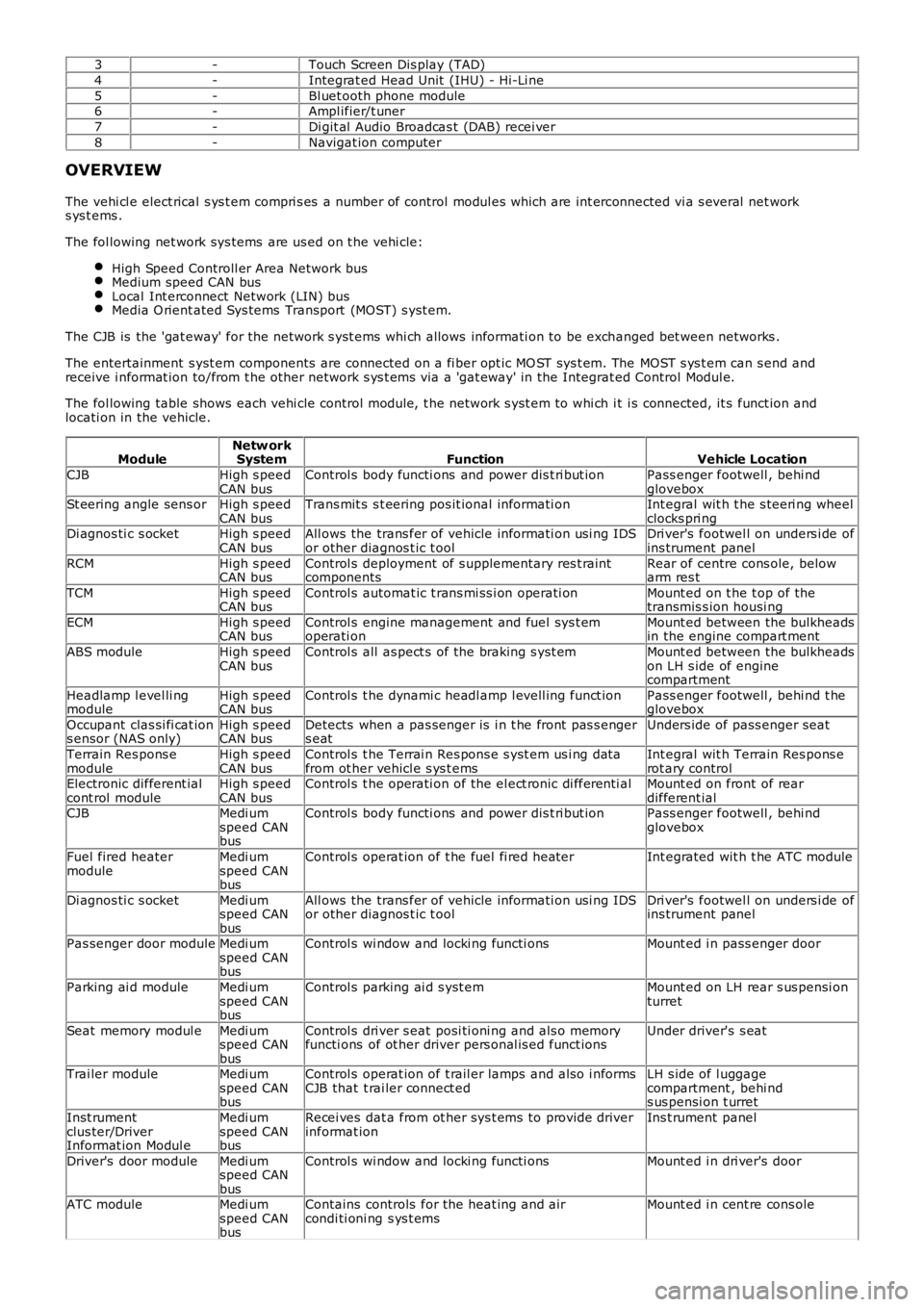
The vehi cl e elect rical s ys t em compri s es a number of control modul es which are int erconnected vi a s everal net works ys t ems .
The fol lowing net work sys tems are us ed on t he vehi cle:
High Speed Controll er Area Network busMedium speed CAN busLocal Int erconnect Network (LIN) busMedia O rient ated Sys tems Transport (MOST) s yst em.
The CJB is the 'gat eway' for the net work s yst ems whi ch allows informati on to be exchanged bet ween networks .
The entertainment s yst em components are connected on a fi ber opt ic MO ST sys t em. The MOST s ys t em can s end andreceive i nformat ion to/from t he other network s ys t ems via a 'gat eway' in the Integrat ed Control Modul e.
The fol lowing table shows each vehi cle control modul e, t he network s yst em to whi ch it i s connected, it s funct ion andlocati on in the vehicle.
ModuleNetw orkSystemFunctionVehicle Location
CJBHigh s peedCAN busControl s body functi ons and power dis t ri but ionPass enger footwell , behi ndgloveboxSt eering angle sens orHigh s peedCAN busTrans mit s s t eering pos it ional informati onInt egral wit h t he s teeri ng wheelclocks pri ngDi agnos ti c s ocketHigh s peedCAN busAll ows the trans fer of vehicle informati on usi ng IDSor other diagnos t ic t oolDri ver's footwel l on unders i de ofins trument panel
RCMHigh s peedCAN busControl s deployment of s upplementary res t raintcomponentsRear of centre cons ole, belowarm res t
TCMHigh s peedCAN busControl s automat ic t rans mi ss i on operati onMount ed on t he t op of thetransmis s ion housi ng
ECMHigh s peedCAN busControl s engine management and fuel sys t emoperati onMount ed between the bulkheadsin the engine compart ment
ABS moduleHigh s peedCAN busControl s all as pect s of the braking s yst emMount ed between the bulkheadson LH s ide of enginecompartment
Headlamp l evel li ngmoduleHigh s peedCAN busControl s t he dynami c headl amp l evell ing funct ionPass enger footwell , behi nd t heglovebox
Occupant clas si fi cat ions ensor (NAS only)High s peedCAN busDetects when a pas senger is i n t he front pas s engers eatUnders ide of pass enger seat
Terrain Res pons emoduleHigh s peedCAN busControl s t he Terrai n Res pons e s yst em us i ng dat afrom ot her vehicl e s ys t emsInt egral wit h Terrain Res pons erot ary controlElectronic different ialcont rol moduleHigh s peedCAN busControl s t he operati on of the el ect ronic di fferenti alMount ed on front of reardifferent ialCJBMedi umspeed CANbus
Control s body functi ons and power dis t ri but ionPass enger footwell , behi ndglovebox
Fuel fired heatermoduleMedi umspeed CANbus
Control s operat ion of t he fuel fi red heaterInt egrated wit h t he ATC module
Di agnos ti c s ocketMedi umspeed CANbus
All ows the trans fer of vehicle informati on usi ng IDSor other diagnos t ic t oolDri ver's footwel l on unders i de ofins trument panel
Pas senger door moduleMedi umspeed CANbus
Control s wi ndow and locki ng functi onsMount ed i n pass enger door
Parking ai d moduleMedi umspeed CANbus
Control s parking ai d s yst emMount ed on LH rear s us pensi onturret
Seat memory modul eMedi umspeed CANbus
Control s dri ver s eat posi ti oni ng and als o memoryfuncti ons of ot her driver pers onal is ed funct ionsUnder driver's s eat
Trai ler moduleMedi umspeed CANbus
Control s operat ion of t rail er lamps and als o i nformsCJB that t rai ler connect edLH s ide of l uggagecompartment , behi nds us pensi on t urret
Inst rumentclus ter/DriverInformat ion Modul e
Medi umspeed CANbus
Recei ves dat a from ot her sys t ems to provide driverinformat ionIns t rument panel
Driver's door moduleMedi umspeed CANbus
Control s wi ndow and locki ng functi onsMount ed i n dri ver's door
ATC moduleMedi umspeed CANbus
Contains controls for the heat ing and aircondi ti oni ng s ys t emsMount ed i n cent re cons ole
Page 2073 of 3229
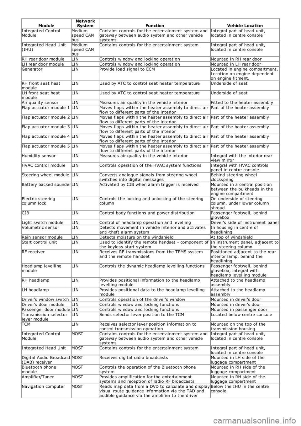
ModuleNetw orkSystemFunctionVehicle Location
Integrat ed Cont rolModuleMedi umspeed CANbus
Contains controls for the ent ert ai nment sys t em andgateway between audio s ys t em and ot her vehicles ys t ems
Int egral part of head uni t,located i n cent re cons ole
Integrat ed Head Unit(IHU)Medi umspeed CANbus
Contains controls for the ent ert ai nment sys t emInt egral part of head uni t,located i n cent re cons ole
RH rear door moduleLINControl s wi ndow and locki ng operati onMount ed i n RH rear door
LH rear door moduleLINControl s wi ndow and locki ng operati onMount ed i n LH rear doorGenerat orLINProvide l oad s ignal t o ECMLocat ed in engine compart ment .Locat ion on engine dependenton engine fit ment.
RH front s eat heatmoduleLINUs ed by ATC t o cont rol s eat heat er temperat ureUnders ide of s eat
LH front s eat heatmoduleLINUs ed by ATC t o cont rol s eat heat er temperat ureUnders ide of s eat
Air quali ty sens orLINMeasures air qualit y i n t he vehi cl e int eri orFit ted t o t he heater as sembl y
Flap act uat or modul e 1LINMoves fl aps wit hi n t he heat er ass embl y to direct airfl ow t o different parts of t he i nt eri orPart of t he heat er as s embly
Flap act uat or modul e 2LINMoves fl aps wit hi n t he heat er ass embl y to direct airfl ow t o different parts of t he i nt eri orPart of t he heat er as s embly
Flap act uat or modul e 3LINMoves fl aps wit hi n t he heat er ass embl y to direct airfl ow t o different parts of t he i nt eri orPart of t he heat er as s embly
Flap act uat or modul e 4LINMoves fl aps wit hi n t he heat er ass embl y to direct airfl ow t o different parts of t he i nt eri orPart of t he heat er as s embly
Flap act uat or modul e 5LINMoves fl aps wit hi n t he heat er ass embl y to direct airfl ow t o different parts of t he i nt eri orPart of t he heat er as s embly
Humi di ty sens orLINMeasures air qualit y i n t he vehi cl e int eri orInt egral wit h t he int eri or rearview mirror
HVAC control modul eLINControl s operat ion of t he HVAC s ys t em funct ionsInt egral wit h HVAC controlspanel i n cent re cons ole
St eering wheel moduleLINConverts analogue s ignals from s teering wheels wit ches i nto di git al mes s agesBehi nd s teering wheelclocks pri ngBatt ery backed s ounderLINActi vat ed by CJB when alarm t ri gger i s receivedMount ed i n a central pos it ionbetween t he bulkheads i n t heengi ne compartment
Electric st eeringcolumn l ockLINControl s t he locking and unlocki ng of the st eeri ngcol umnOn unders ide of s t eeringcol umn, under lower columns hroud
CJBLINControl body funct ions and power di st ributi onPass enger footwell , behi ndglovebox
Light s wit ch moduleLINControl of headlamp operat ion and l evel lingDri ver's s i de of ins trument panelVolumet ri c s ens orLINDetects movement i n vehicle i nterior and act ivatesanti -t heft alarm s ys temIn hous ing in centre ofheadl ining
Rain sens or modul eLINDetects mois t ure on t he wi nds hiel dAt top of windshi el dSt art cont rol unitLINUs ed to identi fy t he remote hands et - component oft he keyles s s t art s yst emIn ins trument panel, adjacent tothe st eeri ng col umnRF recei verLINRecei ves RF trans mi s si ons from t he TPMS s yst emand t he remot e hands etPosi ti oned adjacent t o the rearint erior l amp, behi nd theheadl ining
Headlamp l evel li ngmoduleLINControl s t he dynami c headl amp l evell ing funct ionsPass enger footwell , behi ndglovebox, int egral wit hheadl amp levell ing module
RH headlampLINProvides pos it ional i nformati on to the headlamplevell ing moduleAtt ached t o t he headl ampass embl y
LH headlampLINProvides pos it ional dat a t o t he headlamp levell ingmoduleAtt ached t o t he headl ampass embl y
Driver's window s wi tchLINControl s operat ion of t he driver's wi ndowMount ed i n dri ver's door
Driver's door moduleLINControl s wi ndow and locki ng functi onsMount ed i n dri ver's doorPas senger door moduleLINControl s wi ndow and locki ng functi onsMount ed i n pass enger door
Trans mi ss ion sel ect orl ever moduleLINSends sel ect or l ever pos it ion t o t he TCMLocat ed bel ow centre cons ole
TCMLINRecei ves s elect or l ever pos it ion i nformat ion tocont rol t rans mis s ion operat ionMount ed on t he t op of thetransmis s ion housi ngIntegrat ed Cont rolModuleMOSTContains controls for the ent ert ai nment sys t em andgateway between audio s ys t em and ot her vehicles ys t ems
Int egral part of head uni t,located i n cent re cons ole
Integrat ed Head UnitMOSTContains controls for the ent ert ai nment sys t emInt egral part of head uni t,located i n cent re cons oleDi gi tal Audio Broadcas t(DAB) recei verMOSTRecei ves di git al radi o broadcast sMount ed i n LH s ide of t heluggage compartmentBluet oot h phonemoduleMOSTControl s t he operati on of the Bl uet ooth phones ys t emMount ed i n RH s i de of theluggage compartment
Ampl ifi er/TunerMOSTProvides ampl ifi cat ion for the ent ert ainments ys t ems and recepti on of radio RF broadcas t sMount ed i n RH s i de of theluggage compartment
Navigati on comput erMOSTReads map data from a DVD t o cal cul ate and di spl ayvis ual route gui dance i nformat ion vi a t he TAD andaudi ble gui dance via the ampl ifier to the driver
Below t he IHU i n t he cent recons ole