2006 LAND ROVER FRELANDER 2 heater
[x] Cancel search: heaterPage 2076 of 3229
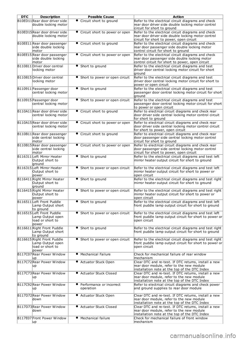
DT C
Description Possible Cause Action
B10ED11 Rear door driver s ide
double l ocki ng motor Circui t short to ground Refer to t he elect rical circuit di agrams and check
rear door dri ver s i de doubl e locking mot or cont rol
ci rcuit for s hort t o ground
B10ED15 Rear door driver s ide
double l ocki ng motor Circui t short to power or open Refer to t he elect rical circuit di agrams and check
rear door dri ver s i de doubl e locking mot or cont rol
ci rcuit for s hort t o power, open circui t
B10EE11 Rear door pas s enger
s i de double locki ng
mot or Circui t short to ground Refer to t he elect rical circuit di agrams and check
rear door pas senger si de doubl e locking mot or
control ci rcuit for short to ground
B10EE15 Rear door pas s enger
s i de double locki ng
mot or Circui t short to power or open Refer to t he elect rical circuit di agrams and check
rear door pas senger si de doubl e locking mot or
control ci rcuit for short to power, open circui t
B110811 Driver door central
l ocking motor Short to ground Refer to t he elect rical circuit di agrams and t est
driver door central l ocki ng motor circui t for s hort
ground
B110815 Driver door central
l ocking motor Short to power or open circui t Refer to t he elect rical circuit di agrams and t est
driver door central l ocki ng motor circui t for s hort t o
power or open ci rcuit
B110911 Pas s enger door
central locki ng motor Short to ground Refer to t he elect rical circuit di agrams and t est
pas s enger door central locki ng mot or circui t for s hort
ground
B110915 Pas s enger door
central locki ng motor Short to power or open circui t Refer to t he elect rical circuit di agrams and t est
pas s enger door central locki ng mot or circui t for s hort
t o power or open ci rcuit
B110A11 Rear door driver s ide
central locki ng motor Circui t short to ground Refer to el ect ri cal circui t diagrams and check rear
door dri ver s ide cent ral locki ng mot or control ci rcuit
for s hort to ground
B110A15 Rear door driver s ide
central locki ng motor Circui t short to power or open Refer to el ect ri cal circui t diagrams and check rear
door dri ver s ide cent ral locki ng mot or control ci rcuit
for s hort to power, open ci rcuit
B110B11 Rear door pas s enger
s i de cent ral locking
mot or Circui t short to ground Refer to el ect ri cal circui t diagrams and check rear
door pass enger s i de cent ral locking mot or cont rol
ci rcuit for s hort t o ground
B110B15 Rear door pas s enger
s i de cent ral locking
mot or Circui t short to power or open Refer to el ect ri cal circui t diagrams and check rear
door pass enger s i de cent ral locking mot or cont rol
ci rcuit for s hort t o power, open circui t
B116311 Left Mirror Heater
Out put short to
ground Short to ground Refer to t he elect rical circuit di agrams and t est l eft
mirror heat er output circuit for s hort to ground
B116315 Left Mirror Heater
Out put short to
power Short to power or open circui t Refer to t he elect rical circuit di agrams and t est l eft
mirror heat er output circuit for s hort to power or
open circui t
B116411 Ri ght Mirror Heat er
Out put short to
ground Short to ground Refer to t he elect rical circuit di agrams and t est right
mirror heat er output circuit for s hort to ground
B116415 Ri ght Mirror Heat er
Out put short to
power Short to power or open circui t Refer to t he elect rical circuit di agrams and t est right
mirror heat er output circuit for s hort to power or
open circui t
B116511 Left Front Puddle
Lamp Out put s hort
t o ground Short to ground Refer to t he elect rical circuit di agrams and t est l eft
front puddle l amp output circui t for s hort t o ground
B116515 Left Front Puddle
Lamp Out put open
l oad or short to
power Short to power or open circui t Refer to t he elect rical circuit di agrams and t est l eft
front puddle l amp output circui t for s hort t o power or
open circui t
B116611 Ri ght Front Puddle
Lamp Out put s hort
t o ground Short to ground Refer to t he elect rical circuit di agrams and t est right
front puddle l amp output circui t for s hort t o ground
B116615 Ri ght Front Puddle
Lamp Out put open
l oad or short to
power Short to power or open circui t Refer to t he elect rical circuit di agrams and t est right
front puddle l amp output circui t for s hort t o power or
open circui t
B117C07 Rear Power W indow
up Mechanical Fai lure Check for mechanical fail ure of rear wi ndow
mechanis m
B117C72 Rear Power W indow
up Act uator Stuck Open Cl ear DTC and re-tes t. If DTC returns , ins t al l a new
rear door module, refer to the new modul e
i nst all ati on not e at t he t op of the DTC Index
B117C73 Rear Power W indow
up Act uator Stuck Cl os ed Cl ear DTC and re-tes t. If DTC returns , ins t al l a new
rear door module, refer to the new modul e
i nst all ati on not e at t he t op of the DTC Index
B117C92 Rear Power W indow
up Performance or incorrect
operati on Refer to el ect ri cal circui t diagrams and check power
and ground suppli es to rear door modul e
B117D72 Rear Power W indow
down Act uator Stuck Open Cl ear DTC and re-tes t. If DTC returns , ins t al l a new
rear door module, refer to the new modul e
i nst all ati on not e at t he t op of the DTC Index
B117D73 Rear Power W indow
down Act uator Stuck Cl os ed Cl ear DTC and re-tes t. If DTC returns , ins t al l a new
rear door module, refer to the new modul e
i nst all ati on not e at t he t op of the DTC Index
B117E07 Front Power W i ndow
up Mechanical fail ure Check for mechanical fail ure of front window
mechanis m
Page 2160 of 3229
16-Central Juncti on Box (CJB)
17-Ri ght -Hand (RH) door control modul e
18-RH ext eri or mirror19-RH ext eri or mirror mot or
OVERVIEW
The rear view mirrors compris e an int erior mi rror mount ed t o t he winds hield, and an exterior mi rror mount ed on each frontdoor cheater.
For Japanes e s peci fi cat ion vehicles , a driver proximi ty mirror is ins tall ed on t he LH front corner of t he hood.
The t ypes of mi rrors and as s oci at ed operat ing funct ions ins tal led depend on t he specificati on and trim level of the vehicle.
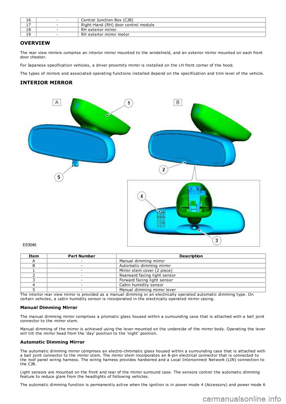
INTERIOR MIRROR
ItemPart NumberDescription
A-Manual dimming mirrorB-Aut omati c dimming mirror
1-Mirror s tem cover (2 piece)
2-Rearward faci ng li ght sens or3-Forward faci ng li ght sens or
4-Cabi n humidi ty s ens or
5-Manual dimming mirror leverThe int eri or rear vi ew mi rror is provi ded as a manual di mmi ng or an electrically operated aut omat ic di mmi ng t ype. Oncert ai n vehicles , a cabi n humidi ty s ens or i s i ncorporat ed i n the el ect ri cal ly operated mi rror cas ing.
Manual Dimming Mirror
The manual di mmi ng mirror compri s es a pri smati c glas s hous ed wi thi n a s urroundi ng cas e t hat is at tached wit h a bal l jointconnector t o t he mirror s t em.
Manual di mming of t he mi rror is achieved usi ng t he lever mount ed on t he unders ide of t he mirror body. Operati ng the leverwil l ti lt t he mi rror head from t he 'day' pos it ion t o t he 'ni ght ' pos it ion.
Automatic Dimming Mirror
The automat ic di mming mirror compri ses an el ect ro-chromati c glas s housed wit hi n a s urroundi ng cas e that is at t ached wi tha ball joint connector t o t he mirror s t em. The mirror s tem incorporat es an 8-pi n electrical connect or that i s connected t ot he roof panel wi ri ng harness . The wi ring harnes s provi des hardwired and a Local Interconnect Net work (LIN) connect ion t ot he CJB.
Light s ens ors are mount ed on t he front and rear of t he mi rror surround case. The s ensors cont rol t he automat ic dimmingfeat ure t o reduce gl are from the headli ght s of fol lowi ng vehi cl es .
The automat ic di mming funct ion is permanent ly acti ve when t he ignit ion i s in power mode 4 (Access ory) and power mode 6
Page 2163 of 3229
Revers e gear mirror dip i s only avail abl e when memory mi rrors are ins t al led, and revers e gear mi rror di p is enabled wit hint he ins trument cl ust er.
If the driver sel ect s a memory recall funct ion us ing the memory s eat swit ch pack, the driver's memory seat and exteriormemory mi rrors are moved to a s tored memory pos i ti on.For addit ional informat ion, refer t o: Seat s (501-10 Seati ng, Des cript ion and Operat ion).
Mirror Power Fold and Auto Fold Feature
Exteri or mirrors wit h t he power fold/auto fold feature incorporat e a motor located in t he hinge of each ext eri or mirror arm.Operat ion of t he power fold feature is achieved us ing t he exteri or mirror s wit ch pack. Operat ion of t he auto fold feature isachi eved us ing the remote hands et.
The power fold funct ion is acti ve when t he ignit ion i s in power mode 6 (Ignit ion).
Both ext eri or mirrors wil l power fol d when t he mi rror s wi tch pack 'L' and 'R' s wit ches are pres s ed t oget her. Pres s ing t hes wit ches again wil l unfol d t he mi rrors .
W hen t he i ns t rument clus ter i s configured for the aut o fol d feat ure, t he mirrors wi ll fol d in when the remot e hands et lockbutt on is pres sed. The mi rrors wi ll unfold when the vehicl e is unl ocked us ing t he remot e handset unlock butt on.
• NOTE: If the mirrors are folded in usi ng t he mirror s wit ch pack (power fol d) and the vehicle i s t hen locked, s ubs equentunlocki ng of the vehicle wil l not unfol d t he mirrors .
W hen t he remote hands et unl ock but ton i s operated, t he CJB recogni zes t he remote hands et for that vehicle andacknowledges t he request . The door control modul es are connect ed direct ly t o t he AJB for power s uppl y to the ext eriormi rror folding motors.
W hen t he vehicle i s locked the door cont rol modules revers e t he pol ari ty of t he mi rror fold motor, power and groundconnecti ons to operat e t he mi rrors i n t he oppos it e direct ion.
Exterior Mirror Heating
Exteri or mirror heati ng is provi ded wit h heater element s bonded to t he back of the mirror glas s. Power s uppl y for t he mi rrorheat ing el ements i s provided by the corresponding driver or pas s enger door control modul e via the AJB.
The door control modul es receive a power s uppl y from the AJB, and are bot h connected on the medi um s peed CAN bus t ot he ATC module. A ground t erminal from each door control modul e completes the circuit. The ATC modul e automat icall ycont rol s the mirror heati ng functi on whenever the ignit ion i s in power mode 4 (Access ory) and power mode 6 (Igni ti on).For addit ional informat ion, refer t o: Cont rol Component s (412-01 Cli mat e Cont rol , Descripti on and Operat ion).
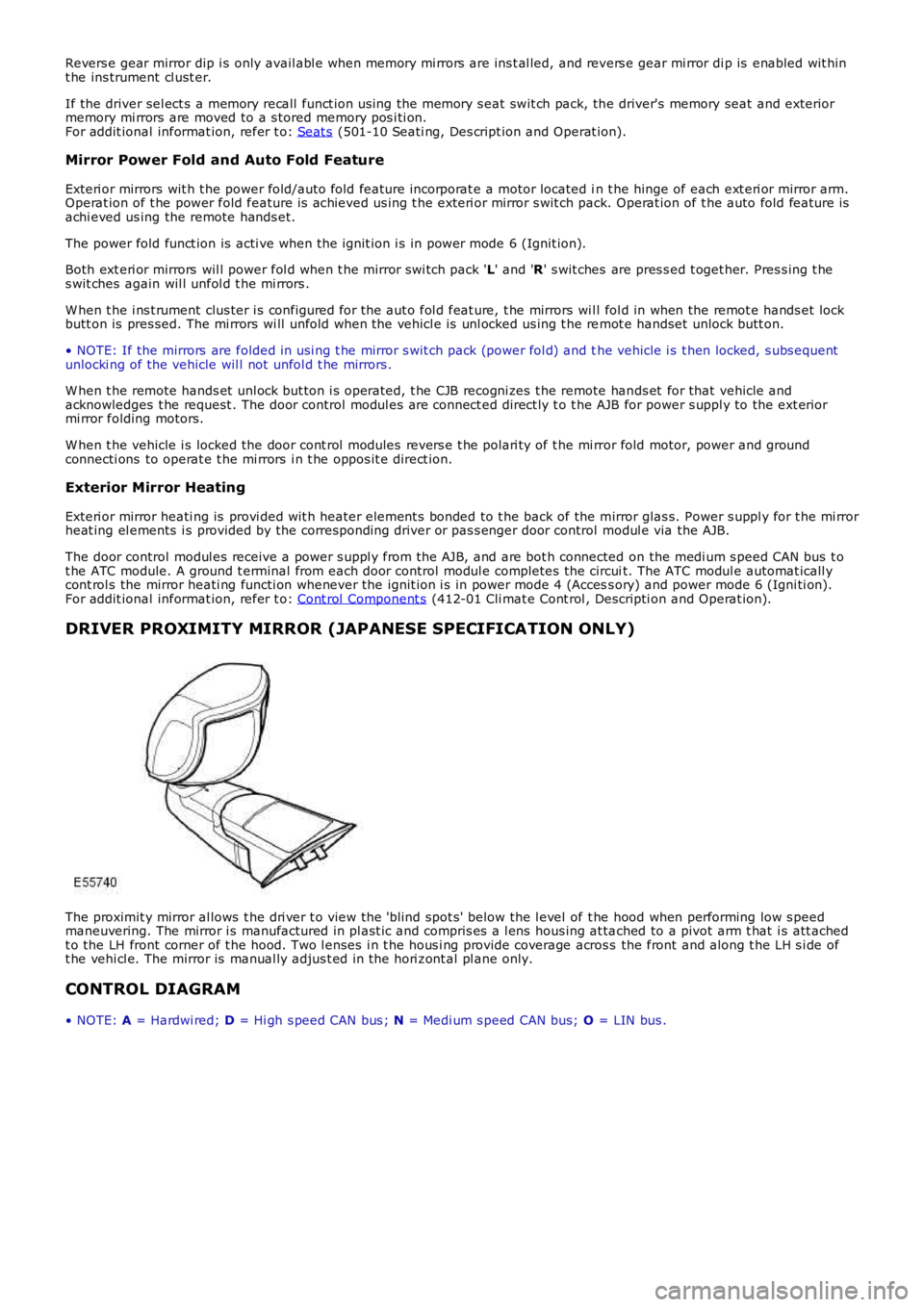
DRIVER PROXIMITY MIRROR (JAPANESE SPECIFICATION ONLY)
The proximit y mirror al lows t he dri ver t o view the 'blind spot s' below the l evel of t he hood when performing low s peedmaneuvering. The mirror i s manufactured in pl ast ic and compris es a l ens hous ing at tached to a pivot arm t hat i s att achedt o the LH front corner of t he hood. Two l enses i n t he hous i ng provide coverage across the front and along t he LH s i de oft he vehi cl e. The mirror is manual ly adjus t ed in the hori zont al pl ane only.
CONTROL DIAGRAM
• NOTE: A = Hardwi red; D = Hi gh s peed CAN bus ; N = Medi um s peed CAN bus; O = LIN bus .
Page 2166 of 3229
Publi s hed: 11-May-2011
Rear View Mirrors - Rear View Mirrors
Diagnosi s and Tes ti ng
Principles of Operation
For a detail ed descripti on of the rear vi ew mirror s ys t ems, refer t o t he rel evant Descripti on and Operat ion s ecti on in t heworks hop manual .REFER to: Rear View Mirrors (501-09 Rear View Mirrors, Des cri pt ion and Operati on).
Inspection and Verification
CAUTION: Di agnos is by s ubs ti tut ion from a donor vehicle is NO T acceptabl e. Subs ti tut ion of cont rol modules doesnot guarant ee confirmat ion of a faul t, and may als o caus e addit ional fault s i n t he vehi cl e being t est ed and/or t he donorvehi cl e.
1. Verify t he cus t omer concern.1.
2. Vis ually ins pect for obvious s igns of mechani cal or electrical damage.2.
Visual InspectionMechanicalElectrical
Condit ion, correct ins tal lati on and s ecurit y of rear view mirrorsFus es/rel ays (refer to elect rical guide)W iring harnes sCorrect engagement of el ect ri cal connect orsLoos e or corroded connecti ons
3. If an obvious cause for an obs erved or report ed concern is found, correct t he caus e (if pos s ible) beforeproceeding t o t he next s t ep.3.
4. If t he caus e is not vis ually evi dent , check for Di agnos ti c Trouble Codes (DTCs) and refer t o t he DTC Index.4.
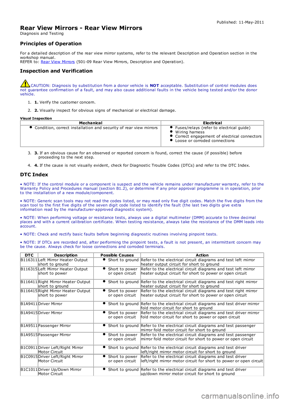
DTC Index
• NOTE: If the control modul e or a component i s s us pect and the vehicle remains under manufacturer warrant y, refer t o theW arranty Pol icy and Procedures manual (s ect ion B1.2), or determine i f any pri or approval programme is in operat ion, pri ort o the ins tall ati on of a new module/component.
• NOTE: Generic scan t ool s may not read the codes li st ed, or may read only fi ve digit codes . Mat ch the five di git s from t hes can tool to the firs t fi ve di git s of the seven digi t code l is ted to ident ify t he faul t (t he las t t wo digi ts gi ve ext rainformat ion read by the manufact urer-approved diagnost ic s ys tem).
• NOTE: W hen performing volt age or res is t ance t est s , always use a digi tal mult imeter (DMM) accurat e t o t hree deci malplaces and wit h a current cal ibrat ion cert ificate. W hen tes ti ng res i st ance, always take the res is tance of the DMM l eads i ntoaccount.
• NOTE: Check and recti fy bas ic faul ts before beginni ng diagnos t ic rout ines i nvol vi ng pinpoint t es t s.
• NOTE: If DTCs are recorded and, aft er performi ng the pi npoi nt tes ts , a fault is not present , an int ermi tt ent concern maybe t he caus e. Always check for loose connect ions and corroded terminals .
DT CDescriptionPossible CausesActionB116311Left Mirror Heat er Outputs hort t o groundShort t o groundRefer t o t he electrical ci rcuit diagrams and tes t l eft mi rrorheater output circui t for s hort t o ground
B116315Left Mirror Heat er Outputs hort t o powerShort t o poweror open circuitRefer t o t he electrical ci rcuit diagrams and tes t l eft mi rrorheater output circui t for s hort t o power or open circui t
B116411Ri ght Mi rror Heat er Outputs hort t o groundShort t o groundRefer t o t he electrical ci rcuit diagrams and tes t right mirrorheater output circui t for s hort t o groundB116415Ri ght Mi rror Heat er Outputs hort t o powerShort t o poweror open circuitRefer t o t he electrical ci rcuit diagrams and tes t right mirrorheater output circui t for s hort t o power or open circui t
B1A9411Driver MirrorShort t o groundRefer t o t he electrical ci rcuit diagrams and tes t dri ver mirrorfol d mot or ci rcuit for short to ground
B1A9415Driver MirrorShort t o poweror open circuitRefer t o t he electrical ci rcuit diagrams and tes t dri ver mirrorfol d mot or ci rcuit for short to power or open ci rcuit
B1A9511Pas senger MirrorShort t o groundRefer t o t he electrical ci rcuit diagrams and tes t pas sengermi rror fold motor circui t for s hort t o ground
B1A9515Pas senger MirrorShort t o poweror open circuitRefer t o t he electrical ci rcuit diagrams and tes t pas sengermi rror fold motor circui t for s hort t o power or open circui t
B1C0911Driver Left/Right Mi rrorMot or CircuitShort t o groundRefer t o t he electrical ci rcuit diagrams and tes t dri verl eft/right mirror mot or ci rcuit for short to groundB1C0915Driver Left/Right Mi rrorMot or CircuitShort t o poweror open circuitRefer t o t he electrical ci rcuit diagrams and tes t dri verl eft/right mirror mot or ci rcuit for short to power or open ci rcuit
B1C1011Driver Up/Down MirrorMot or CircuitShort t o groundRefer t o t he electrical ci rcuit diagrams and tes t dri verup/down mirror mot or ci rcuit for s hort t o ground
Page 2172 of 3229
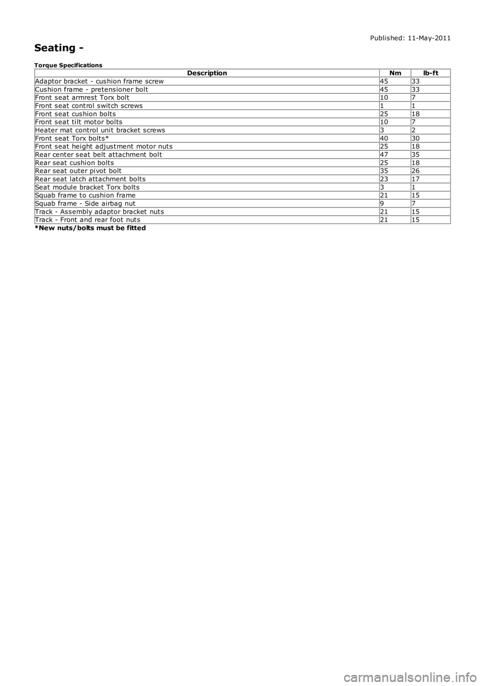
Publi s hed: 11-May-2011
Seating -
Torque SpecificationsDescriptionNmlb-ft
Adaptor bracket - cus hion frame screw4533
Cus hi on frame - pretens ioner bol t4533Front s eat armrest Torx bol t107
Front s eat cont rol s wit ch screws11
Front s eat cus hion bolt s2518Front s eat ti lt mot or bol ts107
Heater mat control uni t bracket s crews32
Front s eat Torx bolt s*4030Front s eat hei ght adjus t ment motor nut s2518
Rear cent er s eat belt at tachment bol t4735
Rear seat cushi on bolt s2518Rear seat outer pi vot bolt3526
Rear seat l at ch att achment bolt s2317
Seat modul e bracket Torx bolt s31Squab frame t o cushi on frame2115
Squab frame - Si de airbag nut97
Track - As s embly adaptor bracket nut s2115Track - Front and rear foot nut s2115
*New nuts/bolts must be fitted
Page 2189 of 3229
Publi shed: 26-Jul-2011
Seating - Heater Mats
Diagnosi s and Tes ti ng
Principles of Operation
Heated s eats incorporate heat er elements in t he cushi on and the backres t of the s eat. Each cus hion heat er el ement has at hermal sens or, whi ch suppli es a feedback temperat ure si gnal t o t he rel at ed s eat heat er modul e. The backres t heat erelement s do not have a thermal sens or, and are regulat ed at the s ame temperat ure as the cus hi on heat er elements .
For a detail ed descripti on of the seat heater mat , refer t o t he rel evant Des cript ion and Operat ion s ecti on in the workshopmanual. REFER to: Seats (501-10, Descripti on and Operat ion).
Inspection and Verification
1. Verify t he cus t omer concern.1.
2. Vis ually ins pect for obvious s igns of mechani cal or electrical damage.2.
Visual inspectionMechanicalElectrical
Seat heat er swi tches condi ti on and ins tal lati onFusesHarnes s es and connect orsSeat heat er modul eSeat heat er swi tchesSeat heat er mat
3. If an obvious cause for an obs erved or report ed concern is found, correct t he caus e (if pos s ible) beforeproceeding t o t he next s t ep.3.
4. If t he caus e is not vis ually evi dent , verify t he sympt om and refer t o t he Sympt om Chart.4.
• NOTE: If the control modul e or a component i s s us pect and the vehicle remains under manufacturer warrant y, refer t o thewarranty poli cy and procedures manual (s ect ion B1.2), or det ermine i f any prior approval programme is i n operati on, priort o the ins tall ati on of a new module/component.
• NOTE: Generic scan t ool s may not read the codes li st ed, or may read only fi ve digit codes . Mat ch the five di git s from t hes can tool to the firs t fi ve di git s of the seven digi t code l is ted to ident ify t he faul t (t he las t t wo digi ts gi ve addi ti onalinformat ion read by the manufact urer approved diagnos t ic s ys tem).
• NOTE: W hen performing el ect ri cal volt age or resi s tance tes t s, al ways us e a digit al mult imet er (DMM) accurate to threedeci mal places , and wi th an up-to-date cali brat ion cert ificate. W hen t es ti ng res is t ance, always take t he res i st ance of t heDMM leads int o account.
• NOTE: Check and recti fy bas ic faul ts before beginni ng diagnos t ic rout ines i nvol vi ng pinpoint t es t s.
• NOTE: Ins pect connect ors for s igns of water ingres s , and pins for damage and/or corros ion.
• NOTE: If DTCs are recorded and, aft er performi ng the pi npoi nt tes ts , a fault is not present , an int ermi tt ent concern maybe t he caus e. Always check for loose connect ions and corroded terminals .
DTC Index
For a compl ete lis t of all di agnos ti c troubl e codes that coul d be l ogged on t his vehicle, pleas e refer to s ect ion 100-00.
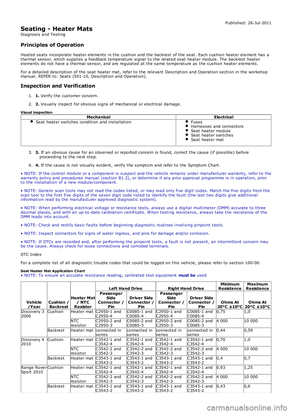
Seat Heater Mat Application C hart• NOTE: To ens ure an accurate res is t ance readi ng, cali brated tes t equi pment must be used
Vehicle/YearCushion /Backrest
Heater Mat/ NT CResistor
Left Hand DriveRight Hand DriveMinimumResistanceMaximumResistance
PassengerSideConnector /Pin
Driver SideConnector /Pin
PassengerSideConnector /Pin
Driver SideConnector /PinOhms At20°C ±10°COhms At20°C ±10°CDi scovery 32006Cushi onHeater matC2950-1 andC2950-4C0085-1 andC0085-4C2950-1 andC2950-4C0085-1 andC0085-40,751,0
NTCres is t orC2950-2 andC2950-3C0085-2 andC0085-3C2950-2 andC2950-3C0085-2 andC0085-34 00010 000
Backres tHeater matconnect ed ins eri esconnect ed ins eri esconnect ed i nseriesconnect ed inseries0,440,59
Di scovery 42010Cushi onHeater matC3542-1 andC3542-4C3542-1 andC3542-4C3542-1 andC3542-4C3542-1 andC3542-40,701,0
NTCres is t orC3542-2 andC3542-3C3542-2 andC3542-3C3542-2 andC3542-3C3542-2 andC3542-34 00010 000
Backres tHeater matC3543-1 andC3543-2C3543-1 andC3543-2C3543-1 andC3543-2C3543-1 andC3543-20,40,7
Range RoverSport 2010Cushi onHeater matC3542-1 andC3542-4C3542-1 andC3542-4C3542-1 andC3542-4C3542-1 andC3542-40,931,25
NTCres is t orC3542-2 andC3542-3C3542-2 andC3542-3C3542-2 andC3542-3C3542-2 andC3542-34 00010 000
Backres tHeater matC3543-1 andC3543-2C3543-1 andC3543-2C3543-1 andC3543-2C3543-1 andC3543-20,430,6
Page 2190 of 3229
1
1
2
1
2
3
1
1
2
3
4
5
6
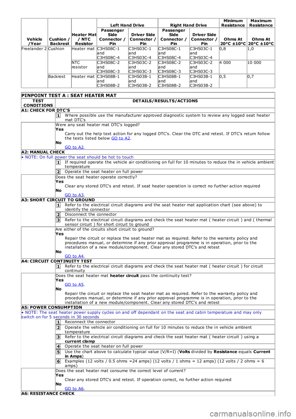
Vehicle/YearCushion /Backrest
Heater Mat/ NT CResistor
Left Hand DriveRight Hand DriveMinimumResistanceMaximumResistance
PassengerSideConnector /Pin
Driver SideConnector /Pin
PassengerSideConnector /Pin
Driver SideConnector /PinOhms At20°C ±10°COhms At20°C ±10°C
Freelander 2Cushi onHeater matC3HS08C-1andC3HS08C-4
C3HS03C-1andC3HS03C-4
C3HS08C-1andC3HS08C-4
C3HS03C-1andC3HS03C-4
0,81,0
NTCres is t orC3HS08C-2andC3HS08C-3
C3HS03C-2andC3HS03C-3
C3HS08C-2andC3HS08C-3
C3HS03C-2andC3HS03C-3
4 00010 000
Backres tHeater matC3HS08B-1andC3HS08B-2
C3HS03B-1andC3HS03B-2
C3HS08B-1andC3HS08B-2
C3HS03B-1andC3HS03B-2
0,50,7
PINPOINT TEST A : SEAT HEATER MAT
T ESTCONDIT IONSDET AILS/RESULT S/ACT IONS
A1: CHECK FOR DT C'S
W here poss i bl e us e t he manufacturer approved diagnost ic sys tem t o review any logged s eat heatermat DTC'sW ere any s eat heat er mat DTC's logged?YesCarry out the hel p t ext acti on for any l ogged DTC's . Clear t he DTC and ret es t. If DTC's ret urn foll owt he tes t s li st ed below GO t o A2.NoGO to A2.A2: MANUAL CHECK
• NOTE: On full power the seat s houl d be hot t o t ouch
If required operate the vehicle ai r condit ioning on ful l for 10 mi nut es t o reduce the in vehicle ambientt emperature
Operat e t he s eat heater on full power
Does the seat heater operate correctl y?YesClear any s tored DTC's and retes t. If s eat heater operat ion i s correct no furt her acti on requiredNoGO to A3.A3: SHORT CIRCUIT T O GROUND
Refer t o t he electrical ci rcuit diagrams and the seat heater mat appli cat ion chart (see above) toi dent ify the connect orDi sconnect t he connect or
Refer t o t he electrical ci rcuit diagrams and check t he s eat heater mat ( heat er ci rcuit ) and ( t hermals ensor circui t ) for s hort circui t to groundAre eit her of t he ci rcuit s s hort circui t to ground?YesRepair t he ci rcuit or repl ace the s eat heat er mat as required. Refer to the warranty pol icy andprocedures manual, or determine i f any prior approval programme is i n operat ion, prior t o t hei ns t allat ion of a new module/component . Clear any s tored DTC's and ret estNoGO to A4.
A4: CIRCUIT CONT INUIT Y T EST
Refer t o t he electrical ci rcuit diagrams and check t he s eat heater mat ( heat er ci rcuit ) for ci rcuitcont inui ty
Does the seat heater mat heater circuit pas s t he cont inuit y t es t ?YesGO to A5.NoRepair t he ci rcuit or repl ace the s eat heat er mat as required. Refer to the warranty pol icy andprocedures manual, or determine i f any prior approval programme is i n operat ion, prior t o t hei ns t allat ion of a new module/component . Clear any s tored DTC's and ret estA5: POWER CONSUMPT ION
• NOTE: The s eat heat er power s uppl y cycl es on and off dependant on t he s eat and cabin t emperat ure and may onl ys wit ch on for 5 s econds in 30 secondsReconnect the connect or
Operat e t he vehi cl e air condit ioning on full for 10 minutes to reduce t he i n vehi cl e ambi entt emperatureRefer t o t he electrical ci rcuit diagrams and check t he s eat heater mat ( heat er ci rcuit ) us ing acurrent clampOperat e t he s eat heater on full power
Us e t he chart above t o calculat e t ypi cal value (V/R=I) (Volts di vi ded by Resistance equals Currentin Amps)Examples (12 vol ts / 0.5 ohms =24 amps ) (12 volt s / 1 ohms = 12 amps ) (12 volt s / 2 ohms = 6amps )
Does the seat heater mat consume the correct level of current ?YesClear any s tored DTC's and retes t. If operati on correct, no furt her act ion requi redNoGO to A6.A6: RESIST ANCE CHECK
Page 2191 of 3229
1
2
3
4
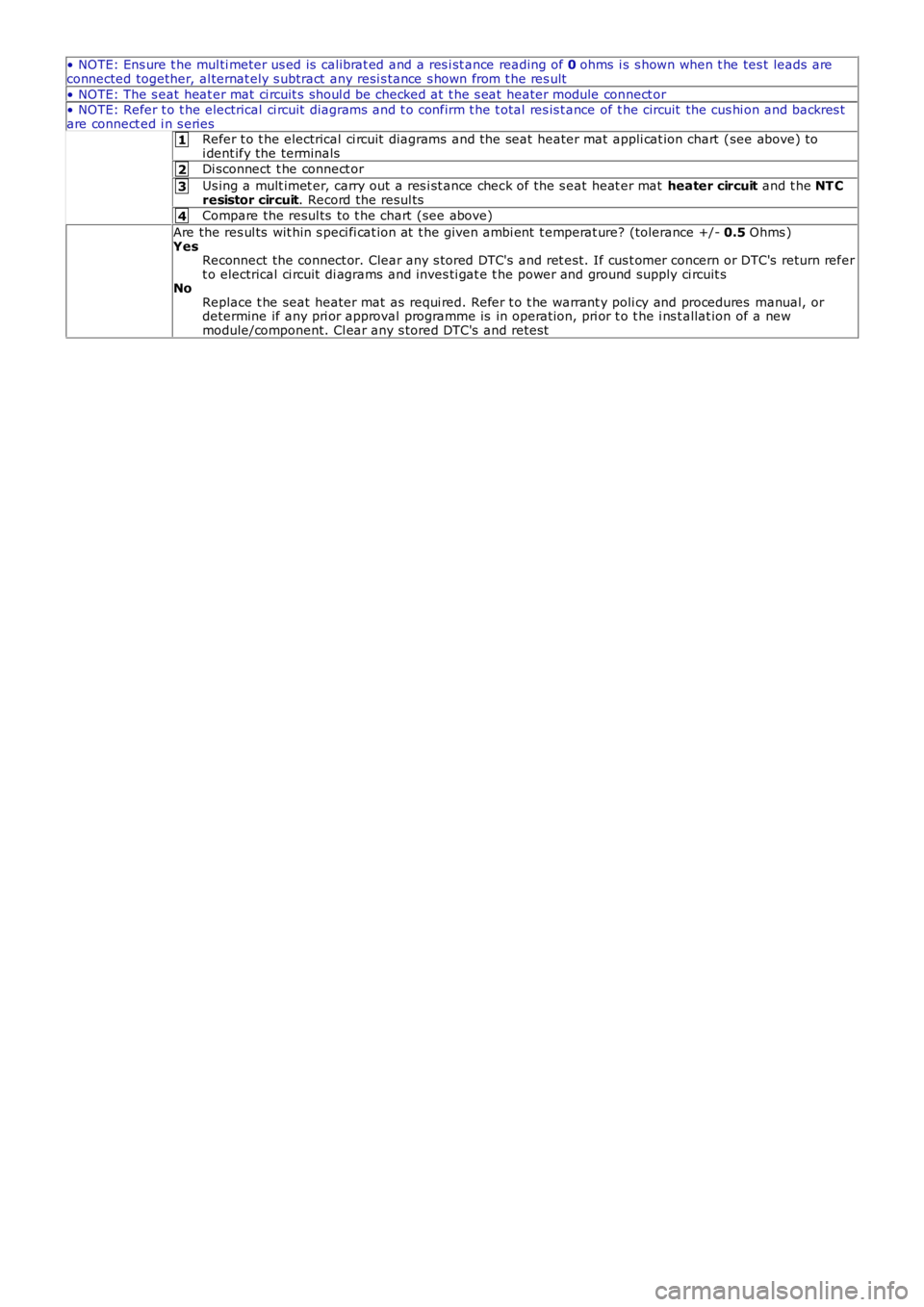
• NOTE: Ens ure t he mul ti meter us ed is cali brat ed and a res i st ance reading of 0 ohms i s s hown when t he tes t leads areconnected together, al ternat ely s ubtract any resi s tance s hown from t he res ult
• NOTE: The s eat heat er mat ci rcuit s s houl d be checked at t he s eat heater module connect or• NOTE: Refer t o t he electrical ci rcuit diagrams and t o confirm t he t otal res is t ance of t he circuit the cus hi on and backres tare connect ed i n s eriesRefer t o t he electrical ci rcuit diagrams and the seat heater mat appli cat ion chart (see above) toi dent ify the terminals
Di sconnect t he connect or
Us ing a mult imet er, carry out a res i st ance check of the s eat heat er mat heater circuit and t he NT Cresistor circuit. Record the resul ts
Compare the resul ts to t he chart (see above)
Are the res ul ts wit hin s peci fi cat ion at t he given ambi ent t emperat ure? (tolerance +/- 0.5 Ohms )YesReconnect the connect or. Clear any s tored DTC's and ret es t. If cus t omer concern or DTC's return refert o electrical ci rcuit di agrams and inves ti gat e t he power and ground supply ci rcuit sNoReplace t he seat heater mat as requi red. Refer t o t he warrant y poli cy and procedures manual, ordetermine if any pri or approval programme is in operat ion, pri or t o t he i ns t allat ion of a newmodule/component. Cl ear any s tored DTC's and retes t