Page 2227 of 3229
Publi s hed: 11-May-2011
Seating - Front Seat Backrest Heater Mat
Removal and Inst all ati on
Removal
• NOTE: Removal s t eps in t his procedure may cont ain i nst all ati on det ail s.
Di sconnect t he bat t ery ground cable.
Refer t o: Specificati ons (414-00 Bat tery and Charging Sys tem -General Informat ion, Specificati ons).
1.
Remove t he front seat backres t cover.
Refer t o: Front Seat Backres t Cover (501-10 Seat ing, Removal andInst all at ion).
2.
3.
Installation
To i nst all , revers e t he removal procedure.1.
Page 2228 of 3229
Publi s hed: 11-May-2011
Seating - Front Seat Cushion Heater Mat
Removal and Inst all ati on
Removal
• NOTE: Removal s t eps in t his procedure may cont ain i nst all ati on det ail s.
Remove t he front seat cushi on cover.
Refer t o: Front Seat Cus hion Cover (501-10 Seati ng, Removal andInst all at ion).
1.
2.
Installation
To i nst all , revers e t he removal procedure.1.
Page 2265 of 3229
17. NOTE: LHD il lus trati on s hown, RHD is s imil ar.
Releas e t he ins trument panel wiring harnes s .
17.
18.
Remove both of t he center, l ower duct s from t he heaterhousi ng.19.
Page 2269 of 3229

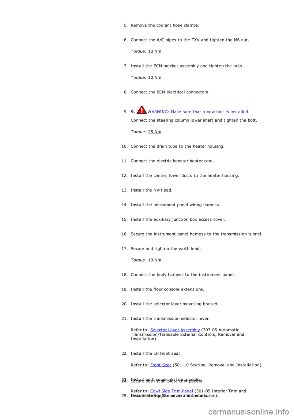
Remove t he cool ant hos e clamps .
5.
Connect t he A/C pipes t o the TXV and ti ght en t he M6 nut .
T orque: 10 Nm 6.
Inst all t he ECM bracket as s embly and ti ght en t he nut s .
T orque: 10 Nm 7.
Connect t he ECM elect rical connectors .
8.
9. W ARNING: Make sure t hat a new bolt i s ins tal led.
Connect t he s teeri ng col umn l ower s haft and t ight en the bol t.
T orque: 25 Nm 9.
Connect t he drain tube t o t he heater hous i ng.
10.
Connect t he electric boos ter heat er core.
11.
Inst all t he cent er, lower ducts t o t he heater hous i ng.
12.
Inst all t he NVH pad.
13.
Inst all t he ins trument panel wiring harnes s .
14.
Inst all t he auxi liary juncti on box acces s cover.
15.
Secure t he ins trument panel harnes s to the trans mi ss i on tunnel.
16.
Secure and t ighten the eart h l ead.
T orque: 10 Nm 17.
Connect t he body harnes s t o t he i ns t rument panel .
18.
Inst all t he fl oor consol e extens ions.
19.
Inst all t he s el ect or lever mount ing bracket.
20.
Inst all t he transmis si on s elector lever.
Refer t o: Sel ect or Lever As sembl y (307-05 Aut omat ic
Trans mi ss ion/Transaxle Ext ernal Cont rol s , Removal and
Inst all at ion).
21.
Inst all t he LH front s eat .
Refer t o: Front Seat (501-10 Seati ng, Removal and Ins tal lati on).
22.
Inst all both cowl s ide t rim panels .
Refer t o: Cowl Si de Tri m Panel (501-05 Interior Tri m and
Ornament ati on, Removal and Ins tal lat ion).
23.
Secure both scuff pl ate t rim panels .
24.
Inst all t he A-pi llar center t rim panels .
25.
Page 2274 of 3229
17.
NOTE: LHD il lus trati on s hown, RHD is s imil ar.
Releas e t he ins trument panel wiring harnes s .
17. 18.
Remove both of t he center, l ower duct s from t he heater
housi ng.
19.
Page 2278 of 3229

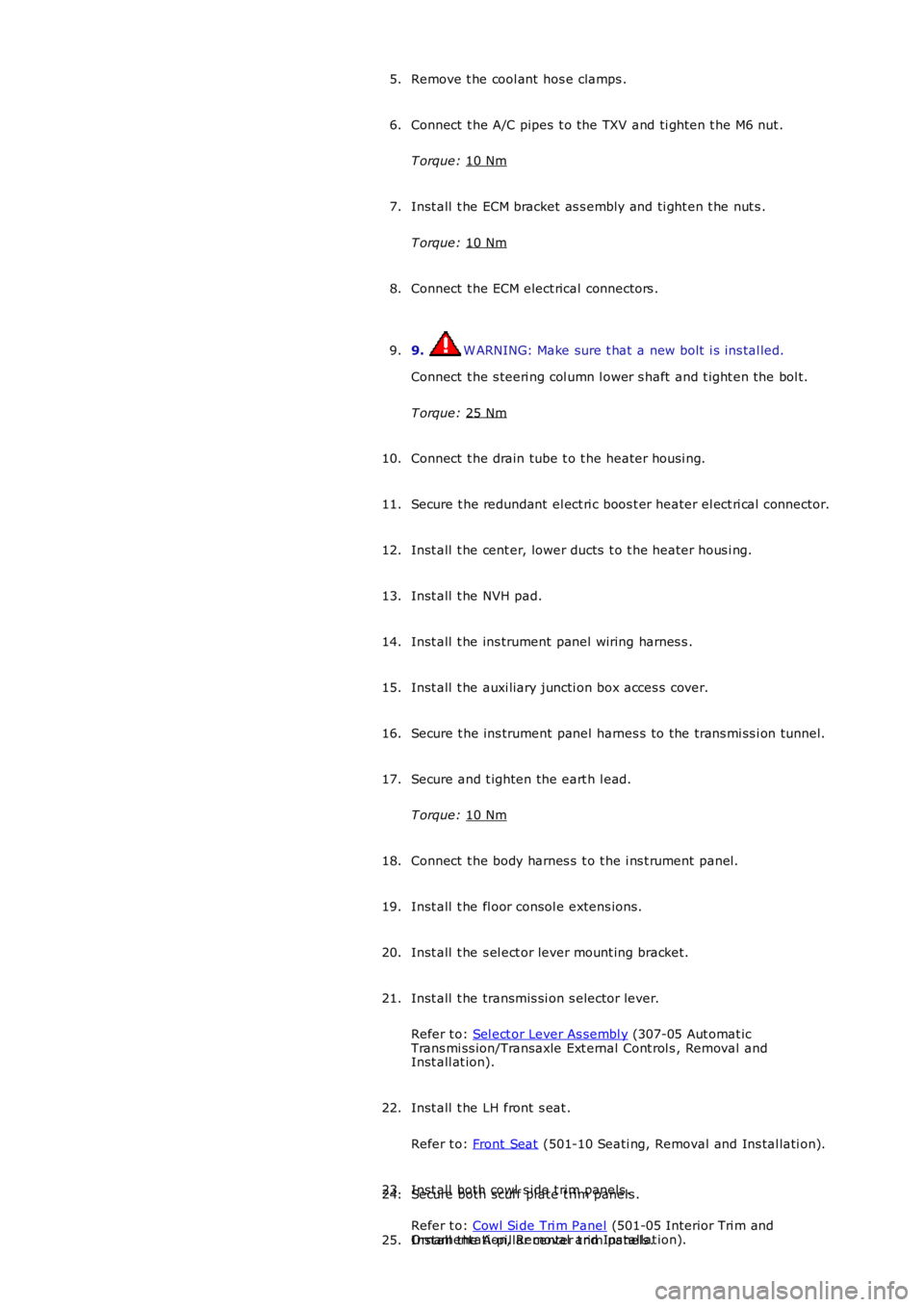
Remove t he cool ant hos e clamps .
5.
Connect t he A/C pipes t o the TXV and ti ght en t he M6 nut .
T orque: 10 Nm 6.
Inst all t he ECM bracket as s embly and ti ght en t he nut s .
T orque: 10 Nm 7.
Connect t he ECM elect rical connectors .
8.
9. W ARNING: Make sure t hat a new bolt i s ins tal led.
Connect t he s teeri ng col umn l ower s haft and t ight en the bol t.
T orque: 25 Nm 9.
Connect t he drain tube t o t he heater hous i ng.
10.
Secure t he redundant el ect ri c boos t er heater el ect ri cal connector.
11.
Inst all t he cent er, lower ducts t o t he heater hous i ng.
12.
Inst all t he NVH pad.
13.
Inst all t he ins trument panel wiring harnes s .
14.
Inst all t he auxi liary juncti on box acces s cover.
15.
Secure t he ins trument panel harnes s to the trans mi ss i on tunnel.
16.
Secure and t ighten the eart h l ead.
T orque: 10 Nm 17.
Connect t he body harnes s t o t he i ns t rument panel .
18.
Inst all t he fl oor consol e extens ions.
19.
Inst all t he s el ect or lever mount ing bracket.
20.
Inst all t he transmis si on s elector lever.
Refer t o: Sel ect or Lever As sembl y (307-05 Aut omat ic
Trans mi ss ion/Transaxle Ext ernal Cont rol s , Removal and
Inst all at ion).
21.
Inst all t he LH front s eat .
Refer t o: Front Seat (501-10 Seati ng, Removal and Ins tal lati on).
22.
Inst all both cowl s ide t rim panels .
Refer t o: Cowl Si de Tri m Panel (501-05 Interior Tri m and
Ornament ati on, Removal and Ins tal lat ion).
23.
Secure both scuff pl ate t rim panels .
24.
Inst all t he A-pi llar center t rim panels .
25.
Page 2724 of 3229

Contents
4
L
Climate control
AIR VENTS ................................................... 101
MANUAL CLIMATE CONTROL ...................... 102
AUTOMATIC CLIMATE CONTROL ................. 103
HEATED WINDOWS AND MIRRORS ............ 104
AUXILIARY HEATER ..................................... 104
ELECTRIC SUNROOF .................................... 105
Convenience features
SUN VISORS ................................................ 107
CLOCK .......................................................... 107
CIGAR LIGHTER ........................................... 109
ASHTRAY ..................................................... 109
AUXILIARY POWER SOCKETS ..................... 110
CUP HOLDERS ............................................. 111
STORAGE COMPARTMENTS ........................ 112
Starting the engine
GENERAL INFORMATION ............................. 113
STARTING A PETROL ENGINE ..................... 114
STARTING A DIESEL ENGINE ....................... 115
DIESEL PARTICULATE FILTER (DPF) ........... 116
Transmission
MANUAL TRANSMISSION ............................ 118
AUTOMATIC TRANSMISSION ...................... 118
TECHNICAL SPECIFICATIONS ...................... 122
Brakes
PRINCIPLE OF OPERATION .......................... 123
HINTS ON DRIVING WITH ABS .................... 123
PARKING BRAKE .......................................... 124
Parking aid
PRINCIPLE OF OPERATION .......................... 126
USING THE PARKING AID ............................ 127
Driving hints
GENERAL DRIVING POINTS ......................... 128
REDUCED ENGINE PERFORMANCE ............. 128
RUNNING-IN ................................................ 128
ECONOMICAL DRIVING ................................ 129
Cruise control
PRINCIPLE OF OPERATION .......................... 130
USING CRUISE CONTROL ............................ 130
Terrain response
PRINCIPLE OF OPERATION .......................... 132
USING TERRAIN RESPONSE ........................ 132
Hill descent control (HDC)
PRINCIPLE OF OPERATION .......................... 136
USING HDC ................................................... 137
Traction control
USING TRACTION CONTROL ........................ 139
Stability control
PRINCIPLE OF OPERATION .......................... 140
USING STABILITY CONTROL ........................ 141
Fuel and refuelling
SAFETY PRECAUTIONS................................. 142
FUEL QUALITY .............................................. 142
RUNNING OUT OF FUEL................................ 144
FUEL CUT-OFF............................................... 144
FUEL FILLER FLAP ........................................ 144
REFUELLING ................................................. 145
TECHNICAL SPECIFICATIONS ....................... 146
Load carrying
GENERAL INFORMATION.............................. 147
LUGGAGE ANCHOR POINTS ......................... 148
LUGGAGE COVERS ....................................... 149
Towing
TOWING A TRAILER...................................... 150
LEVELLING.................................................... 151
ESSENTIAL TOWING CHECKS ...................... 151
RECOMMENDED TOWING WEIGHTS ............ 152
TOW BAR ...................................................... 153
Vehicle care
CLEANING THE ALLOY WHEELS................... 154
CLEANING THE EXTERIOR ............................ 154
CLEANING THE INTERIOR ............................ 155
REPAIRING MINOR PAINT DAMAGE ............ 156
Maintenance
GENERAL INFORMATION.............................. 157
OPENING AND CLOSING THE BONNET......... 160
ENGINE COMPARTMENT OVERVIEW ........... 161
ENGINE OIL CHECK....................................... 162
Page 2735 of 3229

15
Quick start
R
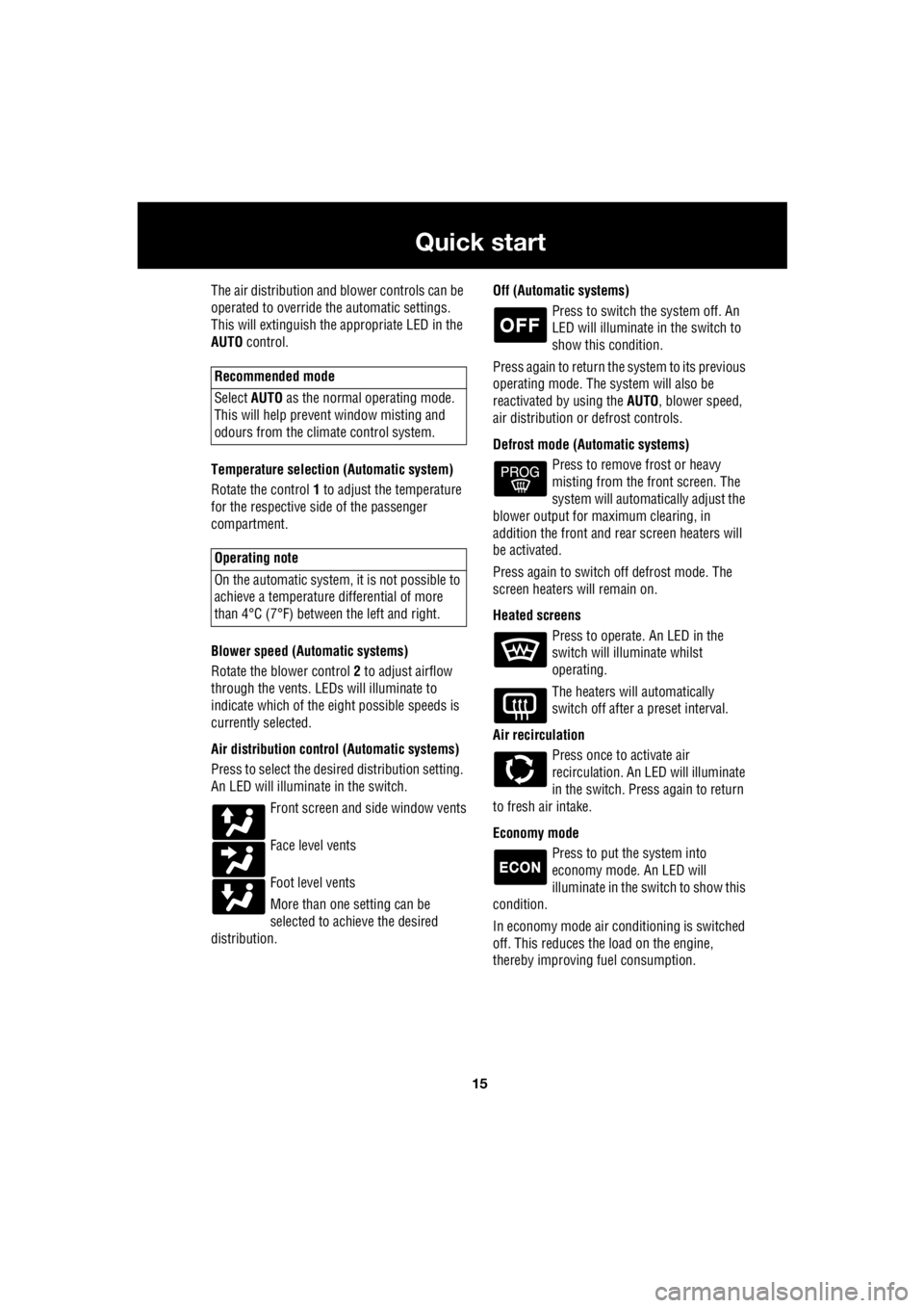
The air distribution and blower controls can be
operated to override the automatic settings.
This will extinguish the appropriate LED in the
AUTO control.
Temperature selection (Automatic system)
Rotate the control 1 to adjust the temperature
for the respective side of the passenger
compartment.
Blower speed (Automatic systems)
Rotate the blower control 2 to adjust airflow
through the vents. LEDs will illuminate to
indicate which of the ei ght possible speeds is
currently selected.
Air distribution contro l (Automatic systems)
Press to select the desi red distribution setting.
An LED will illumina te in the switch.
Front screen and side window vents
Face level vents
Foot level vents
More than one setting can be
selected to achieve the desired
distribution. Off (Automat
ic systems)
Press to switch the system off. An
LED will illuminate in the switch to
show this condition.
Press again to return the system to its previous
operating mode. The system will also be
reactivated by using the AUTO, blower speed,
air distribution or defrost controls.
Defrost mode (Automatic systems) Press to remove frost or heavy
misting from the front screen. The
system will automatically adjust the
blower output for maximum clearing, in
addition the front and rear screen heaters will
be activated.
Press again to switch off defrost mode. The
screen heaters will remain on.
Heated screens Press to operate. An LED in the
switch will illuminate whilst
operating.
The heaters will automatically
switch off after a preset interval.
Air recirculation Press once to activate air
recirculation. An LED will illuminate
in the switch. Press again to return
to fresh air intake.
Economy mode Press to put the system into
economy mode. An LED will
illuminate in the switch to show this
condition.
In economy mode air conditioning is switched
off. This reduces the load on the engine,
thereby improving fuel consumption.
Recommended mode
Select AUTO as the normal operating mode.
This will help prevent window misting and
odours from the climate control system.
Operating note
On the automatic system, it is not possible to
achieve a temperature differential of more
than 4°C (7°F) betwee n the left and right.