2006 LAND ROVER FRELANDER 2 remote control
[x] Cancel search: remote controlPage 1750 of 3229
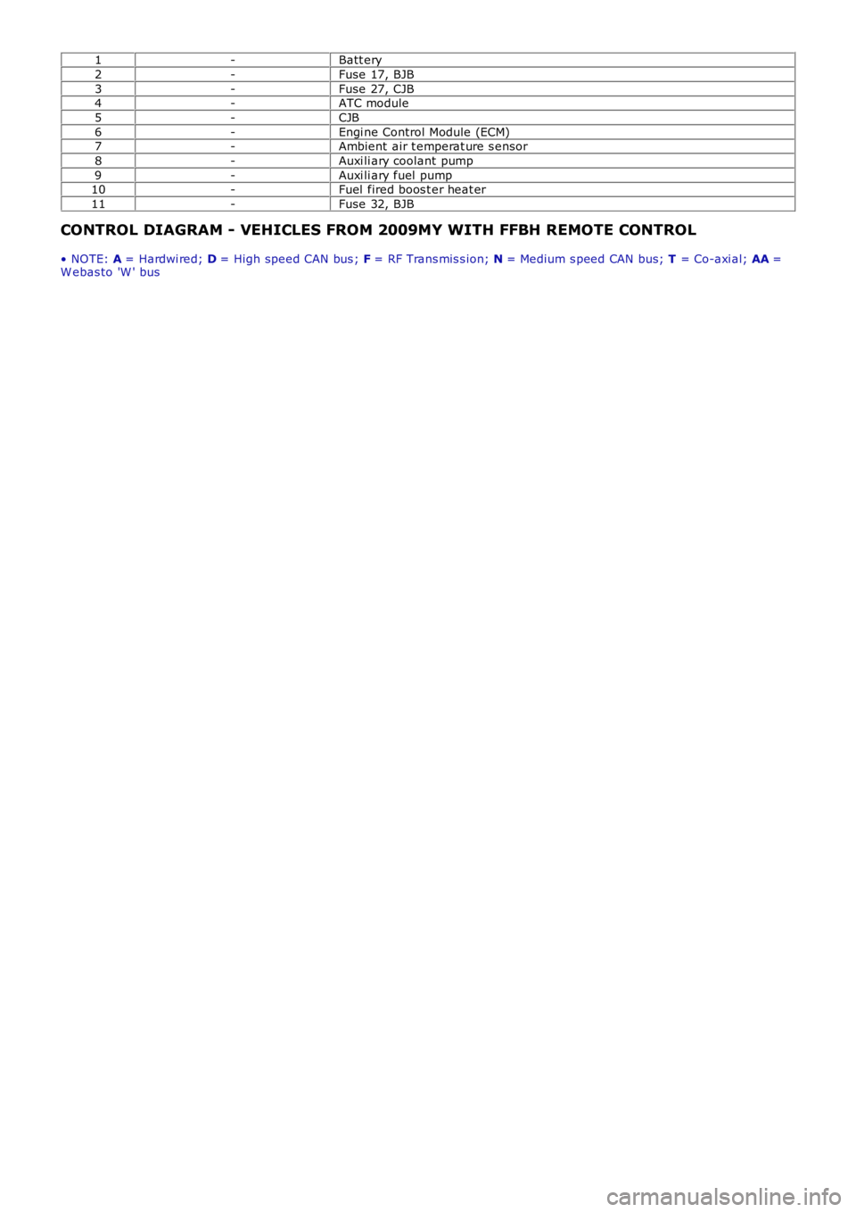
1-Batt ery
2-Fuse 17, BJB
3-Fuse 27, CJB4-ATC module
5-CJB
6-Engi ne Control Module (ECM)7-Ambient air t emperat ure s ensor
8-Auxi li ary coolant pump
9-Auxi li ary fuel pump10-Fuel fired boos t er heat er
11-Fuse 32, BJB
CONTROL DIAGRAM - VEHICLES FROM 2009MY WITH FFBH REMOTE CONTROL
• NOTE: A = Hardwi red; D = High speed CAN bus ; F = RF Trans mis s ion; N = Medium s peed CAN bus; T = Co-axi al; AA =W ebas to 'W ' bus
Page 1754 of 3229
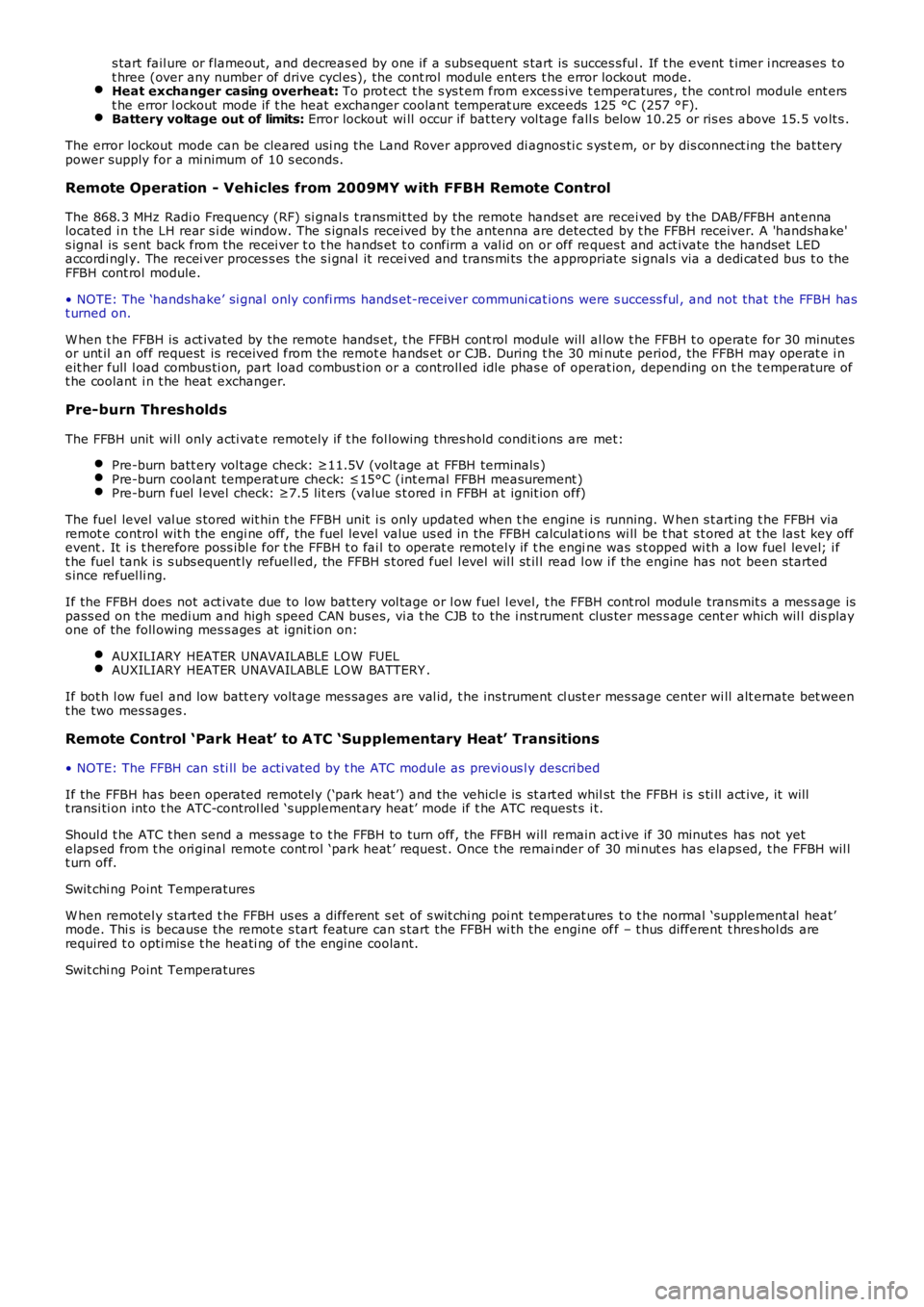
s tart fail ure or flameout, and decreas ed by one if a subs equent s tart is succes s ful . If t he event t imer i ncreas es t ot hree (over any number of drive cycl es), the cont rol module ent ers t he error lockout mode.Heat exchanger casing overheat: To prot ect t he s ys t em from exces s ive t emperatures , t he cont rol module ent erst he error l ockout mode if t he heat exchanger coolant temperat ure exceeds 125 °C (257 °F).Battery voltage out of limits: Error lockout wi ll occur if bat tery vol tage fall s bel ow 10.25 or ris es above 15.5 volt s .
The error lockout mode can be cleared usi ng the Land Rover approved di agnos ti c s ys t em, or by dis connect ing the bat terypower supply for a mi nimum of 10 s econds.
Remote Operation - Vehicles from 2009MY with FFBH Remote Control
The 868.3 MHz Radi o Frequency (RF) si gnal s t ransmit ted by the remote hands et are recei ved by the DAB/FFBH ant ennalocated i n t he LH rear s i de window. The s ignal s received by t he antenna are detected by t he FFBH receiver. A 'handshake's ignal is s ent back from the recei ver t o t he hands et t o confirm a val id on or off reques t and act ivate the handset LEDaccordi ngl y. The recei ver proces s es the s i gnal it recei ved and trans mi ts the appropriate si gnal s via a dedi cat ed bus t o theFFBH cont rol module.
• NOTE: The ‘handshake’ si gnal only confi rms hands et-receiver communi cat ions were s uccess ful , and not that t he FFBH hast urned on.
W hen t he FFBH is act ivated by the remote hands et, t he FFBH cont rol module will al low t he FFBH t o operate for 30 minutesor unt il an off request is received from t he remot e hands et or CJB. During t he 30 minut e period, the FFBH may operat e i neit her full l oad combus ti on, part load combus t ion or a controll ed idle phas e of operat ion, depending on t he t emperature oft he coolant i n t he heat exchanger.
Pre-burn Thresholds
The FFBH unit wi ll only acti vat e remotely if t he fol lowing thres hold condit ions are met:
Pre-burn batt ery vol tage check: ≥11.5V (volt age at FFBH terminals )Pre-burn coolant temperat ure check: ≤15°C (int ernal FFBH measurement )Pre-burn fuel l evel check: ≥7.5 lit ers (value s t ored i n FFBH at ignit ion off)
The fuel level val ue s tored wit hin t he FFBH unit i s only updated when t he engine i s running. W hen s t art ing t he FFBH viaremot e control wit h the engi ne off, the fuel l evel value us ed in the FFBH calculat ions wi ll be t hat s t ored at t he las t key offevent . It i s t herefore poss ibl e for t he FFBH t o fai l to operat e remotel y if t he engine was s t opped wi th a low fuel level; i ft he fuel tank i s s ubs equent ly refuell ed, the FFBH s t ored fuel l evel wil l st il l read l ow i f the engine has not been s tarteds ince refuel li ng.
If the FFBH does not act ivate due to low bat tery vol tage or l ow fuel l evel, t he FFBH cont rol module transmit s a mes s age ispass ed on t he medi um and high speed CAN bus es, vi a t he CJB to the i nst rument clus ter mes s age cent er which wil l dis playone of the foll owing mes s ages at i gnit ion on:
AUXILIARY HEATER UNAVAILABLE LOW FUELAUXILIARY HEATER UNAVAILABLE LOW BATTERY .
If bot h l ow fuel and low batt ery volt age mes sages are val id, t he ins trument cl ust er mes sage center wi ll alt ernate bet weent he two mes sages .
Remote Control ‘Park Heat’ to ATC ‘Supplementary Heat’ Transitions
• NOTE: The FFBH can s ti ll be acti vat ed by t he ATC module as previ ous l y descri bed
If the FFBH has been operated remot el y (‘park heat’) and the vehicl e is st art ed whilst the FFBH i s s ti ll act ive, it willt ransi ti on int o t he ATC-control led ‘s upplement ary heat’ mode if t he ATC request s i t.
Shoul d t he ATC t hen send a mess age t o t he FFBH to turn off, the FFBH will remain active if 30 minut es has not yetelaps ed from t he ori ginal remot e cont rol ‘park heat ’ request . Once t he remai nder of 30 mi nut es has elaps ed, t he FFBH wil lt urn off.
Swit chi ng Point Temperatures
W hen remotel y s tarted t he FFBH us es a different s et of s wit chi ng poi nt temperat ures t o t he normal ‘supplement al heat’mode. Thi s is because the remot e s tart feature can s tart the FFBH wi th the engine off – t hus different t hres hol ds arerequired t o opti mis e t he heati ng of the engine coolant.
Swit chi ng Point Temperatures
Page 1791 of 3229
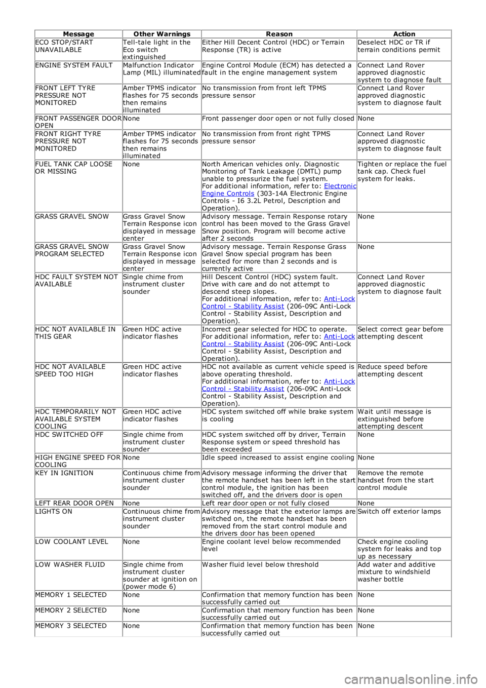
MessageO ther WarningsReasonAction
ECO STOP/STARTUNAVAILABLETel l-tal e li ght in t heEco swi tchext inguis hed
Eit her Hi ll Decent Control (HDC) or TerrainRespons e (TR) i s act iveDes elect HDC or TR i fterrain condit ions permi t
ENGINE SY STEM FAULTMalfunct ion Indi cat orLamp (MIL) il lumi nat edEngi ne Cont rol Module (ECM) has detected afault i n t he engi ne management s ys temConnect Land Roverapproved di agnos ti csys tem t o diagnos e faultFRONT LEFT TY REPRESSURE NOTMONITORED
Amber TPMS indicatorfl ashes for 75 secondsthen remainsil lumi nat ed
No t rans mis s ion from front left TPMSpres sure s ensorConnect Land Roverapproved di agnos ti csys tem t o diagnos e fault
FRONT PASSENGER DOOROPENNoneFront pas s enger door open or not fully cl osedNone
FRONT RIGHT TY REPRESSURE NOTMONITORED
Amber TPMS indicatorfl ashes for 75 secondsthen remainsil lumi nat ed
No t rans mis s ion from front ri ght TPMSpres sure s ensorConnect Land Roverapproved di agnos ti csys tem t o diagnos e fault
FUEL TANK CAP LOOSEOR MISSINGNoneNort h American vehi cl es onl y. Diagnos t icMonit oring of Tank Leakage (DMTL) pumpunabl e to pres surize t he fuel s yst em.For addit ional informati on, refer t o: Elect roni cEngi ne Cont rol s (303-14A Electroni c Engi neCont rol s - I6 3.2L Pet rol, Des cri pt ion andOperati on).
Ti ght en or repl ace t he fueltank cap. Check fuelsys tem for l eaks .
GRASS GRAVEL SNOWGras s Gravel SnowTerrai n Res pons e i condis played in mess agecent er
Advi sory mes s age. Terrain Res pons e rotarycont rol has been moved to the Grass GravelSnow posi ti on. Program will become acti veaft er 2 s econds
None
GRASS GRAVEL SNOWPROGRAM SELECTEDGras s Gravel SnowTerrai n Res pons e i condis played in mess agecent er
Advi sory mes s age. Terrain Res pons e Gras sGravel Snow special program has beens el ect ed for more t han 2 s econds and i scurrent ly acti ve
None
HDC FAULT SY STEM NOTAVAILABLESingle chime fromins trument cl ust ers ounder
Hil l Des cent Cont rol (HDC) sys tem faul t.Dri ve wit h care and do not at tempt t odes cend s teep s lopes .For addit ional informati on, refer t o: Ant i-LockCont rol - St abi li ty As s is t (206-09C Anti -LockCont rol - St abi li ty As s is t , Des cri pti on andOperati on).
Connect Land Roverapproved di agnos ti csys tem t o diagnos e fault
HDC NOT AVAILABLE INTHIS GEARGreen HDC act iveindicator flas hesIncorrect gear s el ect ed for HDC to operate.For addit ional informati on, refer t o: Ant i-LockCont rol - St abi li ty As s is t (206-09C Anti -LockCont rol - St abi li ty As s is t , Des cri pti on andOperati on).
Sel ect correct gear beforeat t empt ing des cent
HDC NOT AVAILABLESPEED TOO HIGHGreen HDC act iveindicator flas hesHDC not avai lable as current vehi cl e s peed isabove operat ing t hres hold.For addit ional informati on, refer t o: Ant i-LockCont rol - St abi li ty As s is t (206-09C Anti -LockCont rol - St abi li ty As s is t , Des cri pti on andOperati on).
Reduce s peed beforeat t empt ing des cent
HDC TEMPORARILY NOTAVAILABLE SY STEMCOOLING
Green HDC act iveindicator flas hesHDC s yst em swi tched off whi le brake s ys t emis cooli ngW ait unt il mes sage i sext inguis hed beforeat t empt ing des cent
HDC SW ITCHED O FFSingle chime fromins trument cl ust ers ounder
HDC s yst em swi tched off by driver, TerrainRespons e s ys t em or s peed thres hold hasbeen exceeded
None
HIGH ENGINE SPEED FORCOOLINGNoneIdl e s peed increased to as s is t engine cool ingNone
KEY IN IGNITIONCont inuous chi me fromins trument cl ust ers ounder
Advi sory mes s age informing the driver thatthe remot e hands et has been left i n t he s tartcont rol module, t he ignit ion has beens wit ched off, and t he dri vers door i s open
Remove t he remotehands et from t he s tartcontrol modul e
LEFT REAR DOOR O PENNoneLeft rear door open or not ful ly cl os edNone
LIGHTS ONCont inuous chi me fromins trument cl ust ers ounder
Advi sory mes s age that t he ext eri or l amps ares wit ched on, t he remot e hands et has beenremoved from the s t art control modul e andthe drivers door has been opened
Swi tch off ext eri or lamps
LOW COOLANT LEVELNoneEngi ne cool ant l evel below recommendedlevelCheck engine cool ingsys tem for l eaks and t opup as neces sary
LOW W ASHER FLUIDSingle chime fromins trument cl ust ers ounder at ignit ion on(power mode 6)
W as her flui d level bel ow t hres hol dAdd water and addi ti vemixt ure t o wi nds hiel dwas her bott le
MEMORY 1 SELECTEDNoneConfirmati on t hat memory funct ion has beens uccess ful ly carried outNone
MEMORY 2 SELECTEDNoneConfirmati on t hat memory funct ion has beens uccess ful ly carried outNone
MEMORY 3 SELECTEDNoneConfirmati on t hat memory funct ion has beens uccess ful ly carried outNone
Page 1811 of 3229
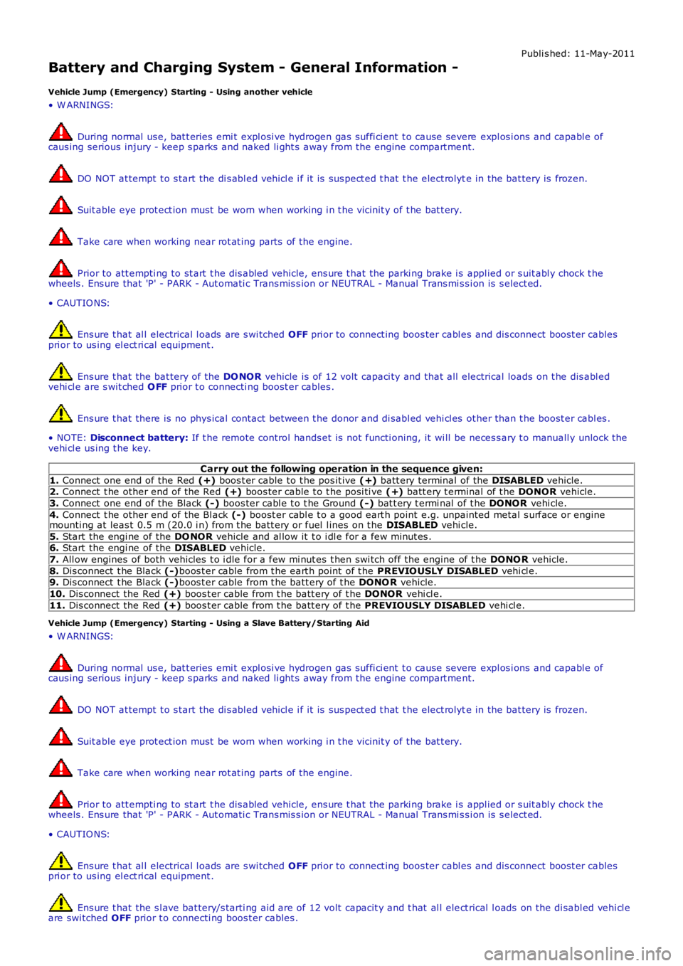
Publi s hed: 11-May-2011
Battery and Charging System - General Information -
Vehicle Jump (Emergency) Starting - Using another vehicle
• W ARNINGS:
During normal us e, bat t eries emi t expl osi ve hydrogen gas suffi ci ent t o cause severe expl os i ons and capabl e ofcaus ing serious injury - keep s parks and naked li ght s away from the engine compart ment.
DO NOT at tempt t o s tart the di s abl ed vehi cl e i f it is sus pect ed t hat t he elect rolyte in the bat tery is frozen.
Suit able eye prot ect ion must be worn when working i n t he vicinit y of t he bat t ery.
Take care when working near rot at ing parts of t he engine.
Prior to att empti ng to st art t he dis abled vehicle, ens ure t hat the parki ng brake i s appl ied or s uit abl y chock t hewheels . Ens ure that 'P' - PARK - Aut omati c Trans mis s ion or NEUTRAL - Manual Trans mi ss i on is s elect ed.
• CAUTIO NS:
Ens ure t hat al l electrical l oads are s wi tched OFF pri or to connect ing boos ter cabl es and dis connect boos t er cablespri or to us ing el ect ri cal equipment .
Ens ure t hat the bat tery of the DO NOR vehicle is of 12 volt capaci ty and that all electrical loads on t he dis abl edvehi cl e are s wit ched O FF prior t o connecti ng boost er cables .
Ens ure t hat there is no phys ical contact between t he donor and di sabl ed vehi cl es other than t he boost er cabl es .
• NOTE: Disconnect battery: If t he remote control hands et is not functi oning, it wi ll be neces s ary t o manuall y unlock thevehi cl e us ing t he key.
Carry out the following operation in the sequence given:
1. Connect one end of the Red (+) boos t er cable to t he pos it ive (+) batt ery terminal of the DISABLED vehicle.2. Connect t he other end of the Red (+) boos ter cable t o t he posi ti ve (+) batt ery t erminal of t he DONOR vehicle.
3. Connect one end of the Black (-) boos ter cabl e t o t he Ground (-) bat t ery t ermi nal of t he DONOR vehi cle.
4. Connect t he other end of the Bl ack (-) boost er cabl e t o a good eart h point e.g. unpainted metal s urface or enginemounti ng at leas t 0.5 m (20.0 i n) from t he batt ery or fuel l ines on t he DISABLED vehi cle.
5. Start the engi ne of the DO NOR vehicle and al low it t o i dl e for a few minut es .6. Start the engi ne of the DISABLED vehicle.
7. All ow engines of both vehicles t o i dle for a few mi nut es t hen swi tch off the engine of t he DONO R vehicle.
8. Dis connect t he Black (-)boos t er cable from t he eart h point of t he PREVIO USLY DISABLED vehi cl e.9. Dis connect t he Black (-)boos t er cable from t he batt ery of t he DONO R vehicle.
10. Dis connect the Red (+) boos t er cable from t he batt ery of t he DONOR vehi cl e.
11. Dis connect the Red (+) boos t er cable from t he batt ery of t he PREVIOUSLY DISABLED vehi cl e.
Vehicle Jump (Emergency) Starting - Using a Slave Battery/Starting Aid
• W ARNINGS:
During normal us e, bat t eries emi t expl osi ve hydrogen gas suffi ci ent t o cause severe expl os i ons and capabl e ofcaus ing serious injury - keep s parks and naked li ght s away from the engine compart ment.
DO NOT at tempt t o s tart the di s abl ed vehi cl e i f it is sus pect ed t hat t he elect rolyte in the bat tery is frozen.
Suit able eye prot ect ion must be worn when working i n t he vicinit y of t he bat t ery.
Take care when working near rot at ing parts of t he engine.
Prior to att empti ng to st art t he dis abled vehicle, ens ure t hat the parki ng brake i s appl ied or s uit abl y chock t hewheels . Ens ure that 'P' - PARK - Aut omati c Trans mis s ion or NEUTRAL - Manual Trans mi ss i on is s elect ed.
• CAUTIO NS:
Ens ure t hat al l electrical l oads are s wi tched OFF pri or to connect ing boos ter cabl es and dis connect boos t er cablespri or to us ing el ect ri cal equipment .
Ens ure t hat the s l ave bat tery/s tarti ng aid are of 12 volt capacit y and t hat al l elect rical l oads on the di sabl ed vehi cl eare swi tched OFF prior t o connecti ng boos t er cables .
Page 1827 of 3229
Publi s hed: 11-May-2011
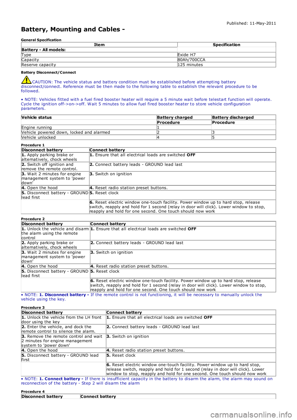
Battery, Mounting and Cables -
General SpecificationItemSpecification
Battery - All models:
TypeExide H7Capaci ty80Ah/700CCA
Res erve capacit y125 minutes
Battery Disconnect/C onnect
CAUTION: The vehicle s t atus and batt ery condit ion mus t be es t abl is hed before att empti ng bat t erydis connect/connect . Reference mus t be t hen made t o t he fol lowing table to es t abl is h t he rel evant procedure t o befol lowed.
• NOTE: Vehicles fit ted wit h a fuel fired boos t er heat er will requi re a 5 mi nute wait before tel es t art funct ion wi ll operate.Cycl e t he ignit ion off->on->off. W ai t 5 mi nutes t o all ow fuel fired boos t er heat er to s t ore vehicle confi gurati onparamet ers .
Vehicle statusBattery chargedBattery discharged
ProcedureProcedure
Engine runni ng1Vehicle powered down, l ocked and alarmed23
Vehicle unl ocked45
Procedure 1
Disconnect batteryConnect battery1. Apply parki ng brake oralt ernat ively, chock wheels1. Ens ure that all el ect ri cal loads are s wit ched O FF
2. Swit ch off i gni ti on andremove the remote cont rol.2. Connect bat t ery l eads - GROUND lead l ast
3. W ai t 2 mi nut es for enginemanagement sys tem t o 'powerdown'
3. Swit ch on ignit ion
4. Open t he hood4. Reset radi o s tat ion preset but tons .
5. Dis connect batt ery - GROUNDl ead firs t5. Reset clock
6. Reset elect ric window one-t ouch facili ty. Power window up t o hard s top, rel eas es wit ch, reapply and hol d for 1 s econd (relay i n door wil l cl ick). Lower window t o s top,reapply and hold for one s econd. One t ouch s hould now work
Procedure 2
Disconnect batteryConnect battery
1. Unlock t he vehi cl e and dis armt he alarm us ing t he remotecont rol
1. Ensure t hat al l el ect ri cal l oads are s wit ched OFF
2. Apply parki ng brake oralt ernat ively, chock wheels2. Connect batt ery l eads - GROUND l ead las t
3. W ai t 2 mi nut es for enginemanagement sys tem t o 'powerdown'
3. Swit ch on i gni ti on
4. Open t he hood4. Res et radio s t ati on pres et but tons .
5. Dis connect batt ery - GROUNDl ead firs t5. Res et cl ock
6. Res et el ect ri c window one-touch facil it y. Power window up to hard s top, rel eases wit ch, reappl y and hold for 1 s econd (rel ay in door wil l cl ick). Lower window t o s top,reapply and hol d for one s econd. One t ouch should now work
• NOTE: 1. Disconnect battery - If the remot e cont rol is not funct ioning, it will be necess ary to manual ly unlock thevehi cl e us ing t he key.
Procedure 3
Disconnect batteryConnect battery1. Unlock t he vehi cl e from the LH frontdoor us i ng the key1. Ens ure t hat al l electrical l oads are s wi tched OFF
2. Enter t he vehi cl e, and dock t heremote control to si lence the al arm.2. Connect batt ery leads - GROUND l ead las t
3. Remove t he remot e cont rol and wai t2 minutes for engi ne managements yst em to 'power down'
3. Swi tch on i gni ti on
4. Open t he hood4. Res et radio st ati on pres et but t ons .
5. Dis connect batt ery - GROUND leadfirst5. Res et cl ock
6. Res et el ect ri c wi ndow one-touch facil it y. Power wi ndow up to hard s t op,release s wit ch, reapply and hol d for 1 second (relay i n door wil l cl ick). Lowerwi ndow to s top, reapply and hold for one s econd. One t ouch s hould now work
• NOTE: 1. Connect battery - If there is ins uffi cient capacit y in the bat tery to di s arm the al arm, t he alarm may sound onreconnect ion of t he bat t ery - St ep 2 wi ll dis arm t he alarm
Procedure 4
Disconnect batteryConnect battery
Page 1869 of 3229
The audi o s yst em is avail abl e in 2 vers ions , Standard and Premium.
The Standard audio s ys t em us es an int ernal ampli fier whi ch di rectl y dri ves the s ys tem s peakers and contai ns a s ingle di s cCompact Di s c (CD) pl ayer. The St andard audio s ys tem is controlled purely from the head uni t and the remote st eeri ngwheel controls . The head uni t is connect ed t o the vehicl e on t he medium speed Controll er Area Network (CAN) bus . Thisall ows the uni t to be int errogat ed for diagnost ic purpos es .
The Premi um audio sys tem compri ses t he fol lowi ng components :
Int egrat ed Audi o Module (IAM)Infotai nment Cont rol Modul e (ICM)Separate audio ampli fierRear seat audio control modul es wit h head phone socket sSurround s ound s peaker s ys t em
Control of t he Premi um audio sys tem is vi a t he ICM located in t he cent er of the i nstrument panel. Control s i gnal s from t heICM are sent t o t he res t of the audi o s ys t em on t he Media Ori ent ated Sys tem Trans port (MOST) ring. The ICM i s the ti mingmas ter for the MOST ri ng and als o host s a gat eway functi on between t he medium s peed CAN bus and the MOST ri ng.Audio s ignals are s ent on t he MOST ring from the Integrat ed Audio Modul e to the amplifier.
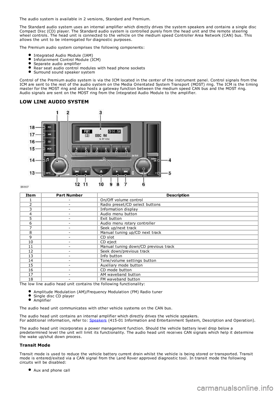
LOW LINE AUDIO SYSTEM
ItemPart NumberDescription
1-On/O ff volume control2-Radio pres et /CD sel ect butt ons
3-Informat ion di spl ay
4-Audio menu but ton5-Exit butt on
6-Audio menu rotary cont rol ler
7-Seek up/next t rack8-Manual t uning up/CD next t rack
9-CD s l ot
10-CD eject11-Manual t uning down/CD previous t rack
12-Seek down/previous t rack
13-Info butt on14-Tone/vol ume s ett ings but ton
15-Auxi li ary mode but ton
16-CD mode but ton17-AM waveband but t on
18-FM waveband but ton
The low li ne audi o head unit cont ains t he fol lowi ng functi onali ty:
Ampli tude Modulat ion (AM)/Frequency Modulat ion (FM) Radio t unerSingle di s c CD playerAmpli fi er
The audi o head unit communicates wit h other vehi cl e s yst ems on the CAN bus .
The audi o head unit contains an internal ampl ifier which direct ly drives t he vehi cle s peakers.For addit ional informat ion, refer t o: Speakers (415-01 Informati on and Entert ainment Syst em, Des cript ion and Operat ion).
The audi o head unit i ncorporat es a power management funct ion. Shoul d t he vehi cl e batt ery l evel drop bel ow apredetermined l evel t he unit wi ll li mit i ts functi onali ty. The audio head unit receives CAN s ignals whi ch hel p it det ermi net he wake up/s hut down proces s .
Transit Mode
Trans it mode i s us ed to reduce the vehicle bat t ery current drain whi ls t t he vehi cl e is bei ng s tored or trans port ed. Trans i tmode i s entered/exi ted vi a a CAN si gnal from the Land Rover approved di agnos ti c tool. In t rans it mode the foll owingcircuit s wi ll be di sabled:
Aux and phone cal l
Page 2048 of 3229
The act ive ant i-theft sys tem monit ors the hi nged panels for unaut horized openi ng. In s ome markets the ant i-theft s ys temals o i ncorporates moni tori ng of the vehicl e int erior and vehicle ti lt s ens i ng.
The act ive ant i-theft al arm s ys t em i s cont rol led by t he fol lowi ng body sys tem cont rol modules :
CJBLeft Hand (LH) and Ri ght Hand (RH) front and rear door modul esIns t rument clus ter.
The CJB is the mai n cont rol ler in the sys tem. The CJB controls t he fol lowi ng securi ty funct ions , in addit ion to ot her vehicl efuncti ons :
Locking, doubl e l ocking and unlockingMonit oring of hi nged panel micros wi tches and panel ajar s t at esInt rus ion det ect ion modul eBatt ery backed sounder or vehicle hornsPass i ve armi ng and dis armi ngPani c alarm funct ionRemote hands et trans ponder readi ngInt eri or light ing.
Two l evels of vehicle ant i-t heft alarm are avai lable; peri meter mode moni tors all openi ng panel s and volumet ric mode (i ffi tt ed) monit ors t he vehi cle i nteri or for int rus ion and, in certai n market s, i t als o i ncorporates a ti lt s ens or t o monit or if t hevehi cl e i s being moved.
• NOTE: Volumet ri c mode and t ilt sens ing are not avai lable i n cert ain market s .
• NOTE: Volumet ri c mode is cancelled if t he vehi cl e is locked wit h any window or roof opening panel not clos ed t o avoi dinadvert ent al arm act ivati on.
The remot e handset provi des the followi ng functi onal it y:
Unlock (central unl ock or s i ngl e point entry)Lock and double lockLiftgate rel eas eApproach li ght ingPani c alarm.
The unlock and lock butt ons als o cont rol a 'lazy' l ock and unl ock feature which wi ll automat icall y cl ose or open t he wi ndowswit h an ext ended press of t he applicable but ton. This feature is onl y avai lable i n cert ain markets and i s cont rol led i nconjuct ion wit h the door modules .
W ARNING: Never doubl e l ock t he vehi cle wi th any pers on or ani mal ins ide.
• NOTE: Double l ocking is only avail abl e i n cert ai n market s .
The remot e handset contains an emergency access key. This can be us ed in the event of fail ure of t he remot e handset ort he vehi cl e batt ery t o unlock t he vehi cl e. The LH door handle contai ns a concealed mechanical key barrel which can beus ed wit h t he emergency key to acces s t he vehicle. This wi ll not dis able t he peri meter or int eri or al arm sys t ems which wi llbe acti vat ed when t he door i s opened. To cancel the al arm, t he remote hands et must be ins ert ed in t he s lot i n t he s tartcont rol module and the s t op/s tart but t on mus t be pres sed.
The remot e handset i s fi tt ed wi th an int egral vanadium lit hium rechargeabl e batt ery. The batt ery i s charged when it isins ert ed int o t he s lot in the st art control modul e.
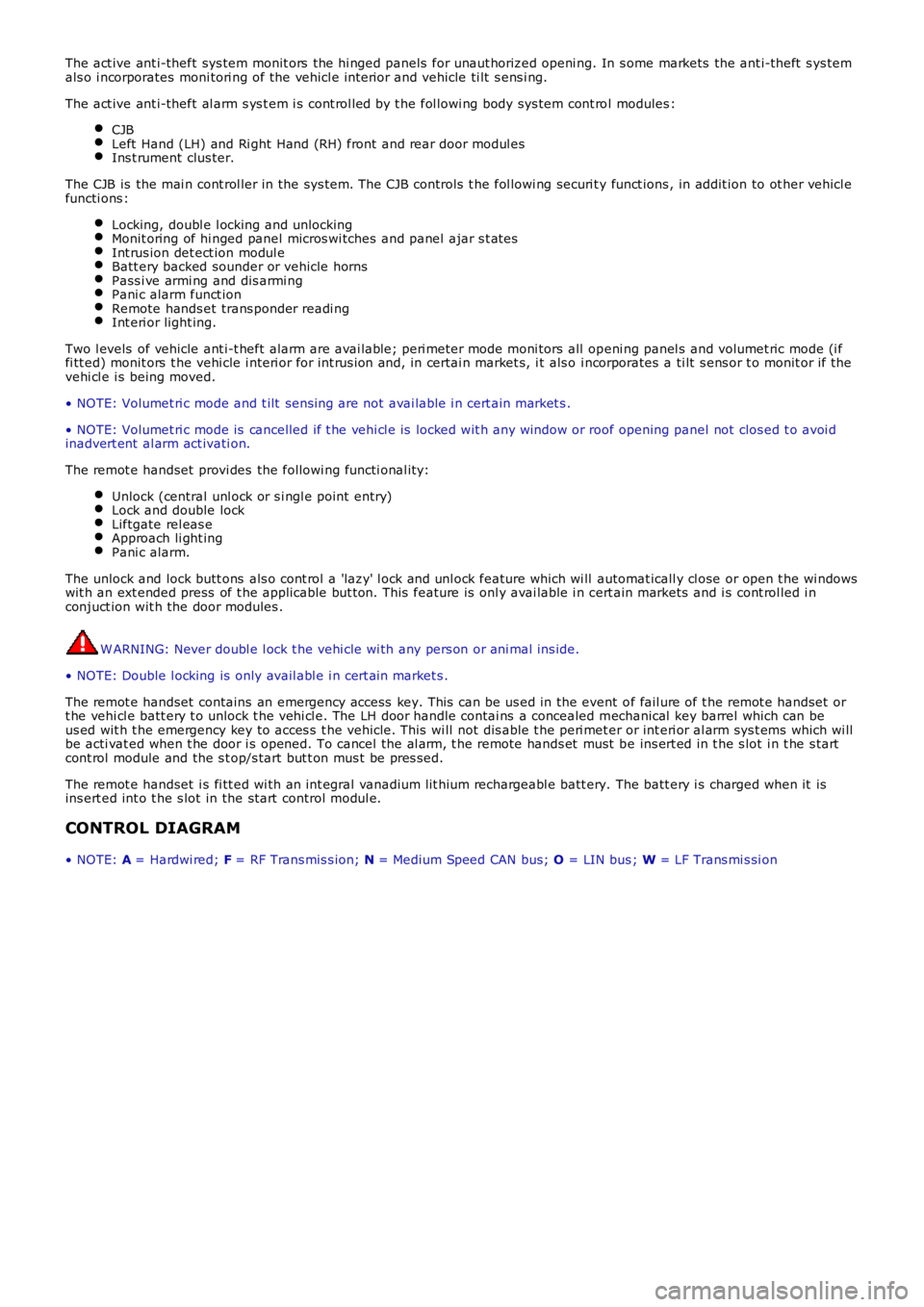
CONTROL DIAGRAM
• NOTE: A = Hardwi red; F = RF Trans mis s ion; N = Medium Speed CAN bus; O = LIN bus ; W = LF Trans mi s si on
Page 2058 of 3229
Publi s hed: 11-May-2011
Anti-Theft - Passive - Anti-Theft - Passive
Des cript ion and Operat ion
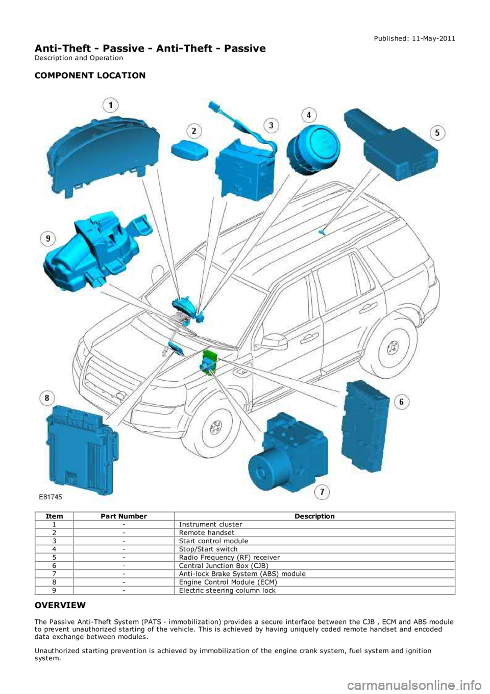
COMPONENT LOCATION
ItemPart NumberDescription1-Ins trument cl us t er
2-Remot e handset
3-St art control modul e4-St op/St art s wit ch
5-Radio Frequency (RF) recei ver
6-Cent ral Juncti on Box (CJB)7-Ant i-lock Brake Sys tem (ABS) module
8-Engine Cont rol Module (ECM)
9-El ect ri c s teeri ng col umn l ock
OVERVIEW
The Pass i ve Ant i-Theft Syst em (PATS - i mmobil izati on) provi des a s ecure int erface bet ween the CJB , ECM and ABS modulet o prevent unauthorized s tarti ng of the vehicle. This i s achi eved by havi ng uni quel y coded remote hands et and encodeddata exchange bet ween modules .
Unaut hori zed st art ing prevent ion i s achi eved by i mmobil izati on of the engine crank sys t em, fuel sys t em and i gni ti ons ys t em.