2006 LAND ROVER FRELANDER 2 remote control
[x] Cancel search: remote controlPage 1092 of 3229
Publi s hed: 11-May-2011
Starting System - TD4 2.2L Diesel - Start Control Unit
Removal and Inst all ati on
Removal
1. NOTE: Thi s s tep must be performed i f replacing t he s tart cont rol
unit .
• NOTE: Make s ure that all keys (remote cont rol hands ets ) are
pres ent when performi ng thi s procedure.
Us ing t he Land Rover approved diagnost ic equipment , int errogat e
t he s tart cont rol uni t and upload t he s tored dat a.
1.
Make t he SRS s ys t em s afe.
Refer t o: Standard W orks hop Pract ices (100-00 General Informat ion,
Des cript ion and Operat ion).
2.
Remove t he dri ver l ower ai r bag.
Refer t o: Dri ver Lower Air Bag Module (501-20B Supplemental
Res traint Sys t em, Removal and Inst all at ion).
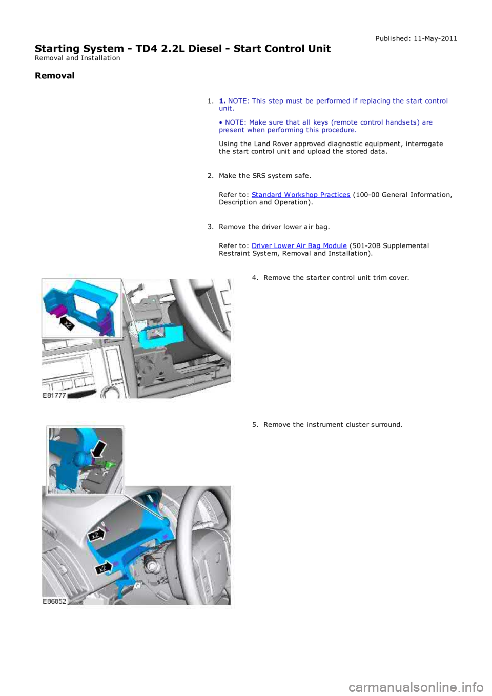
3. Remove t he s tart er cont rol unit t ri m cover.
4. Remove t he ins trument cl ust er s urround.
5.
Page 1216 of 3229
t he fan mot ors . The fan cont rol module confi rms the fan s peed operati on on the same connect ion back t o t he ECM.
Starter Motor Relay
The s tarter mot or relay i s located in t he BJB. The operat ion of t he s tarter mot or relay i s cont rol led by t he ECM whi chprovides a ground pat h for the relay coil , energi zing t he rel ay and cl osi ng t he relay contact s. W hen the relay contacts areclos ed, bat tery vol tage i s s uppl ied, vi a t he s tarter mot or relay, to the st art er modul e s olenoid coil . The st art er s ol enoi d isenergized and connects the s t art er motor wit h a direct batt ery feed t o operate the st art er motor.
Once the engi ne has st art ed, the ECM removes the st art er motor relay ground, opening the relay contacts and t erminati ngt he bat t ery feed to the s t art er s olenoid, which i n t urn s t ops the operat ion of t he starter mot or.For addit ional informat ion, refer t o: Starti ng Sys t em - 3.2L (303-06, Des cript ion and Operat ion).
Fuel Pump Module
The fuel pump i s cont rol led by t he FPDM whi ch in t urn is control led by the ECM. The FPDM provi des pos it ive and negati vefeeds t o t he fuel pump mot or which is cont roll ed wit h a PW M out put . The fuel pump i s run for 2 s econds t o prime the fuels ys t em once igni ti on on is sens ed by t he ECM.For addit ional informat ion, refer t o: Fuel Tank and Lines (310-01, Des cri pt ion and Operati on).
Malfunction Indicator Lamp (MIL)
The MIL is locat ed in the ins trument cl us t er and is i lluminated by a CAN mes s age from t he ECM when an emis s ion relatedfaul t occurs . The ECM als o ill uminat es the MIL when reques t ed to do s o by t he TCM and t o perform a bulb check when theignit ion is s wi tched on. There is no MIL ill uminat ion for non emis si on rel ated engine management fault s . All engine faul tsare recorded wit h a Diagnos t ic Troubl e Code (DTC) whi ch can be ret rieved us ing a Land Rover approved di agnos ti c s yst em.For addit ional informat ion, refer t o: Electroni c Engi ne Controls - 3.2L (303-14, Diagnos is and Tes ti ng).
Generator Feedback Signal
The generator has a Local Interconnect Net work (LIN) bus connect ion direct to t he ECM. The LIN bus is us ed by t he ECM t oreques t vol tage for bat tery charging and t o monit or the fault s t at us of t he generat or.
PRINCIPLES OF OPERATION
Starting Process
The ECM wi ll only al low engine crank, s park and i njector functi ons when the foll owing condi ti ons are met:
A hardwi red Park/Neutral si gnal i s received from the Trans mi ss i on Cont rol Module (TCM)A hardwi red ignit ion s ignal is recei ved from t he CJBA hardwi red crank reques t s ignal is recei ved from t he CJBEncrypt ed data exchange bet ween t he ins trument cl ust er and the ECM is verifi ed.
Before the CJB will s end t he hardwired igni ti on si gnal , it mus t s ati s factori ly complet e t he fol lowi ng:
Exchange encrypt ed data wit h t he s tart control modul e t o vali dat e t he remot e handset.
Addit ional ly, before the CJB will s end t he hardwired crank reques t s ignal i t mus t receive t he fol lowing si gnal s:
Brake s ignal from t he s peed cont rol inhibi t s wit chHardwi red t rans mis s ion in Park (P) or Neutral (N) s ignal from t he s elector lever assembl y.
W i th the remote hands et ins ert ed in the s t art cont rol module and the st op/s tart button is press ed, the st art controlmodule i s sues bat tery vol tage hi gh si gnal on t he LIN bus connecti on to the CJB and the fuel pump i s run for 2 s econds t opri me t he fuel s yst em. The CJB us es this si gnal t oget her wit h t he s top l amp s wit ch signal and is sues a crank requestmes s age on the hi gh s peed CAN bus to the ECM.
The ECM, on receipt of t he crank request mess age, then provides a power and ground supply t o t he s tarter rel ay in theBJB, clos ing the relay contacts . Batt ery volt age is suppli ed via a fus e t hrough t he st art er rel ay and is pas sed to the s t art ermot or s olenoid coi l. The coil is energi zed, clos ing t he s olenoid contacts and allowing a fuse bat tery volt age supply di rectfrom the bat tery to operat e t he s tarter mot or and crank the engine and si mult aneous ly s wi tch t he fuel pump on.
The ECM operat es the st art er motor unti l the engine st art s which i s determined by t he engine s peed exceeding apre-det ermined value.
Auto St art
The ECM has an aut o s tart functi on which all ows the engi ne to cont inue cranking i f the s t op/s tart but ton is released. Thes tarter mot or will operat e unti l the engine st art s or a pre-determined peri od of ti me has el aps ed which i s bas ed on engi necool ant t emperat ure. Low engine cool ant temperat ures al low l onger crank t imes . If the engine does not rot ate or t heengi ne s peed is l ow, the ECM removes t he power s upply and ground from t he st art er rel ay st oppi ng t he crank process .
Start Prevent ion
Operat ion of t he s tart er mot or wi ll not be all owed or wil l be int errupt ed if:
t he engi ne is runni ng and t he engi ne s peed has exceeded a predet ermined s peedt he encrypt ed data exchange bet ween the i nst rument clus t er, ECM, CJB and st art control modul e has fai led t oidenti fy the remote hands ett he gear s elector l ever is not i n t he park 'P' or neutral 'N' pos it ion. The s ignal is det ermi ned from a si gnal from theTCM and al so the t rans mi ss ion mount ed pos it ion s wit cht he brake pedal i s not pres sed.
Engine Stop Process
Page 1217 of 3229
To s top the engine t he s t op/s tart but ton must be pres sed. Forcibly removing t he remote hands et from t he s tart controlmodule will not s top the engine. On models wit h automat ic t rans mi ss i on, once the engi ne has st opped the remotehands et wil l not be releas ed by t he s tart cont rol module unt il the trans mi s si on s el ect or lever is i n t he Park (P) pos i ti on.
Throttle Control
The ECM controls t he posi ti oni ng of the throt t le di sc i n t he electric t hrot tl e us ing i nformat ion from t he APP s ens or and t heTP s ensor. Dat a from t he A/C pres sure s ens or, TCM, ECT s ens or, MAF s ensor and t he MAP/IAT s ensor i s als o us ed todetermine t he correct t hrot tl e cont rol .
The t wo Hall effect sens ors i n t he TP s ens or are des ignat ed 1 and 2. Both sens ors out put an i ncreasi ng vol tage as thet hrott le di s c angl e increas es. Smal l air fl ows t hrough the throt tl e requi re comprehens ive regul at ion, t herefore the vol tageri s e in one of the s ensors increas es more quickl y t han the ot her s ens or whi ch gives accurat e cont rol of t he thrott le andensure t he thrott le di sc is i n t he correct posi ti on.
The ECM moni tors the si gnal s from bot h s ens ors to ens ure they are wit hin the minimum and maximum t hres hol ds and thatt he si gnal s corres pond t o the same thrott le di sc pos it ion. If there is a difference in the si gnal s the ECM us es a defaultt hrott le si gnal calculated from t he electric t hrot tl e load, engi ne s peed and ai r pres s ure and t emperature s ignals . Thes ens or whose out put s ignal i s clos est t o t he calcul ated t hrot tl e dis c angle will be us ed as t he correct output . A faul t codewil l be recorded for the ot her s ens or and t his can be read us ing a Land Rover approved di agnos ti c s ys t em. The ECM t henmonit ors t he remaining s ens or out put s i gnal and compares it agains t t he cal cul ated value. If a difference i n thecomparis on occurs t he ECM wi ll dis count t he output from bot h s ens ors and dis abl e t he electric t hrot tl e cont rol and revert toa l imp home mode. The throt t le di sc has s prings for opening and clos ing and t he ECM can meas ure the l oad appl ied byt hes e s pri ngs for a l oad s ignal . If a fault occurs whi ch prevent s t he damper mot or from being operat ed, the s prings ret urnt he throt t le di sc to a pos i ti on which all ows a t hrot tl e openi ng large enough t o all ow t he vehi cle t o driven, but wi th reduceddri ve abi li ty.
Throt tl e Adapt ions
The ECM has a learning adapti on which al lows t he ECM t o calculate the preci s e cont rol required for t he elect ric throt t ledamper motor. The adapti on process is performed when the ignit ion i s on and t he engine is not runni ng. The t hrot tl e dis cis moved by the damper mot or to t he fully cl osed pos it ion and t he ECM records t he val ues out put by the TP sens orpotenti ometers.
If the permanent batt ery supply t o t he ECM has been removed, t hen previous adapt ions wi ll have been los t. If adapt ionsare st ored, t hen the ECM compares the s t ored adapti on val ues wit h t he current t hrottle angl e and us es an average of thes tored and current values t o create the new adapt ion value.
If the el ect ri c throt t le unit has been repl aced, t he power s upply mus t be removed from t he ECM t o eras e al l previousl ys tored adapt ion values .
Fuel Pressure Regulation
Fuel pres s ure regulati on is cont roll ed by t he ECM t o res pond t o fuel pres s ure demand and provi des s t epl ess cont rol of the
pump output us ing t he FPDM t o control t he pump operat ion. The ECM can vary t he fuel pres s ure to bet ween 55.1 l bf/in2
(3.8 bar) and 72.5 lbf/i n2 (5 bar). The hi gh pres s ure i s only us ed in ext reme condit ions s uch as heavy engine loads andengi ne s tarts .
The ECM us es t he si gnal s from the fuel rail pres s ure/temperat ure s ens or t o det ermi ne informat ion regardi ng t he pres sureand t emperature of the fuel and provi de precis e i njecti on periods , improvi ng engi ne s tarti ng under all condit ions. Theadvant age of controll ing t he fuel pump output pres s ure are t hat pump power consumpt ion is reduced, loweri ng the load ont he power s upply s yst em and reduci ng fuel cons umpt ion, improved s ervi ce life of t he pump and reduced fuel pump nois e.
• NOTE: W hen t he i gni ti on is swi tched off t he FPDM reduces t he fuel li ne pres s ure regul at ion to 29 lbf/in2 (2 bar) to hel preduce inject or leakage.
Knock Control
Knock occurs i n a cyli nder when t he fuel and air s elf i gni tes at t he wrong ti ming. This can occur eit her before or after t hes park i s produced. The fuel mi xt ure can ignit e in different areas of t he combus t ion chamber and res ul ts in a fas tcombus t ion proces s creati ng s everal s eparat e fuel combus t ions which t oget her combi ne to produce a mechani cal knockings ound. The s ounds produce a certain type of vibrat ion through t he engine cylinder block and thes e are detected by t heknock s ensors . The two knock s ens ors det ect knocks on cyl inders 1, 2 and 3 and 4, 5 and 6 respecti vel y.
The vibrat ions act upon the peizo crys t als wi thi n t he sens ors whi ch res ult s in a volt age bei ng produced whi ch is sens ed byt he ECM. The ECM, us ing the CMP sens ors and t he CKP s ensor, can det ermi ne which cylinder(s ) are knocking. The ECM isable t o fil ter t he s ignal t o det ect vibrat ions creat ed duri ng normal engi ne operati on and dis card t hem from the knockdetecti on. The i gni ti on t imi ng is gradual ly advanced unti l the knocki ng is det ect ed once agai n.
Once the ECM has determined knocking is occurri ng usi ng other input s s uch as cat al yti c convert er temperat ure for exampl ein addi ti on to the s i gnal s from t he knock s ens ors , it first retards the ignit ion t imi ng and s ubs equent ly ri chens t he air/fuel i frequired.
Variable Camshaft Timing (VCT) Control
The inl et cams haft i s cont rol led by t he ECM us ing the VCT s olenoid. The exhaus t camshaft is fixed and i ts ti ming cannotbe changed.
Both cams haft s are dri ven i ndirect ly from the cranks haft via a chai n. The chain is driven from a s haft in the gear hous i ngas sembl y.For addit ional informat ion, refer t o: Engi ne - 3.2L (303-01, Descripti on and Operat ion).The VCT all ows t he ECM t o adus t t he inl et cams haft pos it ion i n rel ati on to the cranks haft , al tering t he t imi ng of theopeni ng and clos ing of t he inlet and exhaus t valves rel ati ve to the cranks haft posi ti on. Thi s allows the ECM to provideincreas ed engi ne performance, i mproved i dl e quali ty and reduced emi ss i ons .
Page 1741 of 3229
Publi s hed: 11-May-2011
Auxiliary Climate Control - Fuel Fired Booster Heater
Des cript ion and Operat ion
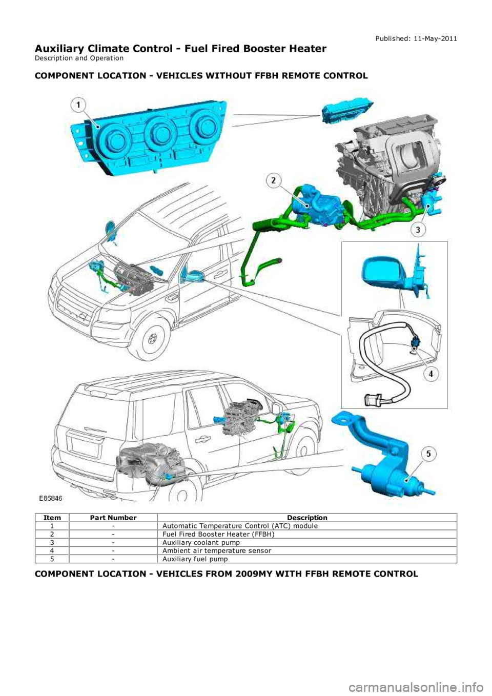
COMPONENT LOCATION - VEHICLES WITHOUT FFBH REMOTE CONTROL
ItemPart NumberDescription1-Automat ic Temperat ure Cont rol (ATC) modul e
2-Fuel Fi red Boos ter Heater (FFBH)
3-Auxili ary coolant pump4-Ambi ent ai r temperat ure s ens or
5-Auxili ary fuel pump
COMPONENT LOCATION - VEHICLES FROM 2009MY WITH FFBH REMOTE CONTROL
Page 1742 of 3229
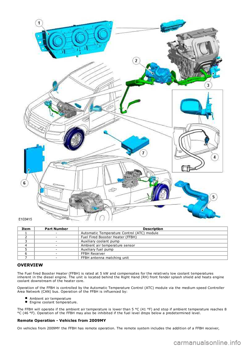
ItemPart NumberDescription
1-Automat ic Temperat ure Cont rol (ATC) modul e2-Fuel Fi red Boos ter Heater (FFBH)
3-Auxili ary coolant pump
4-Ambi ent ai r temperat ure s ens or5-Auxili ary fuel pump
6-FFBH Recei ver
7-FFBH antenna mat chi ng unit
OVERVIEW
The Fuel fired Boos t er Heat er (FFBH) is rated at 5 kW and compensat es for t he rel ativel y low coolant t emperaturesinherent i n the di esel engine. The uni t is locat ed behind t he Right Hand (RH) front fender s plas h s hield and heat s enginecool ant downs tream of t he heat er core.
Operat ion of t he FFBH is controlled by the Aut omati c Temperature Control (ATC) module via the medi um s peed ControllerArea Net work (CAN) bus . Operati on of the FFBH i s influenced by:
Ambient air t emperat ureEngi ne cool ant temperat ure.
The FFBH wil l operate i f the ambient air t emperature is lower than 5 °C (41 °F) and s top if ambient t emperature reaches 8°C (46 °F). Operat ion of t he FFBH may als o be inhibit ed if t he fuel l evel drops below a predet ermi ned level .
Remote Operation - Vehicles from 2009MY
On vehicles from 2009MY the FFBH has remote operati on. The remote sys tem includes t he addi ti on of a FFBH receiver,
Page 1743 of 3229
FFBH antenna mat chi ng uni t and a remote hands et for operati on of the s ys tem. The FFBH unit remains as previ ous l y fi tt edbut has upgraded s oftware. The Engine Cont rol Modul e (ECM) als o has a s oft ware cal ibrat ion upgrade. The ins trumentclus ter mes s age cent er di spl ays FFBH mes s ages when required.
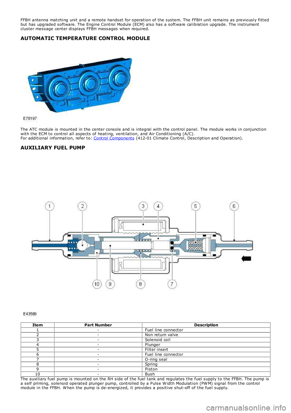
AUTOMATIC TEMPERATURE CONTROL MODULE
The ATC module is mount ed in the center cons ole and is i ntegral wi th the control panel. The module works i n conjunct ionwit h t he ECM t o control al l aspects of heati ng, venti lat ion, and Air Condit ioning (A/C).For addit ional informat ion, refer t o: Cont rol Component s (412-01 Cli mat e Cont rol , Descripti on and Operat ion).
AUXILIARY FUEL PUMP
ItemPart NumberDescription
1-Fuel li ne connect or2-Non return valve
3-Solenoid coi l
4-Pl unger5-Fi lt er i nsert
6-Fuel li ne connect or
7-O-ring s eal8-Spring
9-Pi st on
10-Bus hThe auxi li ary fuel pump is mount ed on the RH s ide of t he fuel t ank and regulates t he fuel s upply t o t he FFBH. The pump isa s elf primi ng, s olenoid operat ed plunger pump, controll ed by a Puls e W idt h Modulation (PW M) s ignal from t he cont rolmodule i n t he FFBH. W hen the pump is de-energized, i t provides a pos it ive s hut-off of t he fuel s uppl y.
Page 1747 of 3229
The ambient air t emperat ure s ensor i s a Negati ve Temperature Co-effi ci ent (NTC) thermis t or, and is mount ed in the LeftHand (LH) door mi rror. The s ens or is connect ed t o the Engi ne Cont rol Module (ECM) which t rans mit s an ambi ent ai rt emperature val ue over t he high speed CAN bus . This value i s rel ayed to the ATC modul e by t he Cent ral Junct ion Box (CJB)over t he medium s peed CAN bus.For addit ional informat ion, refer t o: Cont rol Component s (412-01 Cli mat e Cont rol , Descripti on and Operat ion).
REMOTE CONTROL COMPONENTS - VEHICLES FROM 2009MY WITH FFBH REMOTE
CONTROL
The addi ti on of remot e control retai ns the FFBH component s fit ted t o pre 2009MY vehicl es wit h t he addi ti on of thefol lowing components :
FFBH wit h upgraded s oft ware and cali brat ionFFBH remot e handsetFFBH remot e receiverRecei ver power, communicati on and antenna harnes sesAntenna mat chi ng unit harnes s to connect recei ver co-axial cable t o exis t ing DAB antenna in s ide window.
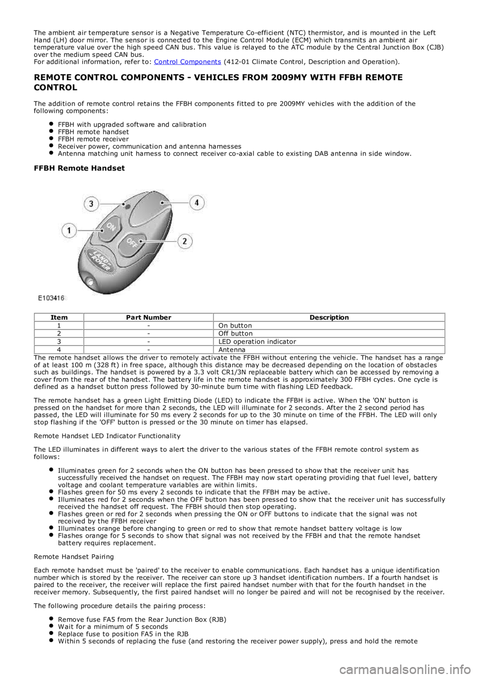
FFBH Remote Handset
ItemPart NumberDescription
1-On butt on2-Off butt on
3-LED operat ion indicator
4-Ant ennaThe remot e handset al lows t he dri ver t o remotely act ivate the FFBH wi thout entering t he vehi cl e. The hands et has a rangeof at leas t 100 m (328 ft ) i n free s pace, alt hough t his di s tance may be decreas ed depending on t he l ocat ion of obst acl ess uch as bui ldings . The hands et is powered by a 3.3 vol t CR1/3N replaceable bat t ery whi ch can be access ed by removi ng acover from the rear of t he hands et . The bat tery li fe in t he remote hands et is approximat ely 300 FFBH cycl es. One cycle i sdefi ned as a hands et butt on pres s fol lowed by 30-minut e burn t ime wi th flas hing LED feedback.
The remot e handset has a green Light Emit ti ng Diode (LED) to indicate the FFBH i s act ive. W hen t he 'O N' but ton i spres s ed on t he hands et for more t han 2 s econds, t he LED wi ll il lumi nat e for 2 s econds . Aft er t he 2 s econd period haspass ed, the LED wil l i ll uminate for 50 ms every 2 s econds for up to the 30 minut e on t ime of t he FFBH. The LED wil l onl ys top flas hing i f the 'OFF' but ton i s pres s ed or the 30 minute on t imer has elaps ed.
Remote Hands et LED Indi cat or Functi onal it y
The LED il lumi nat es i n different ways t o alert the driver to the various s tat es of the FFBH remote control sys t em asfol lows :
Illumi nates green for 2 s econds when t he ON but ton has been press ed t o s how t hat t he receiver unit hass uccess fully recei ved the hands et on request . The FFBH may now s t art operat ing providi ng that fuel l evel , bat teryvolt age and coolant t emperature variabl es are wi thi n li mit s .Flas hes green for 50 ms every 2 s econds t o i ndi cat e t hat the FFBH may be act ive.Illumi nates red for 2 seconds when the OFF but ton has been pres s ed t o s how t hat t he receiver unit has s uccess fullyreceived t he hands et off reques t. The FFBH s hould t hen s top operat ing.Flas hes green or red for 2 s econds when pres s ing t he ON or OFF but t ons t o i ndi cat e that the s i gnal was notreceived by t he FFBH receiverIllumi nates orange before changi ng to green or red to s how t hat remot e hands et batt ery vol tage i s lowFlas hes orange for 5 s econds t o s how t hat si gnal was not received by t he FFBH and t hat t he remote hands etbatt ery requi res replacement .
Remote Hands et Pairi ng
Each remot e hands et mus t be 'paired' t o t he receiver t o enabl e communicati ons . Each hands et has a unique identi fi cat ionnumber whi ch is st ored by t he receiver. The recei ver can s t ore up 3 hands et identi ficat ion numbers . If a fourth hands et ispaired to the recei ver, the recei ver wi ll repl ace the first pai red handset number wit h t hat for t he fourt h handset i n t hereceiver memory. Subsequentl y, t he first paired hands et wi ll no l onger be paired and wil l not be recognis ed by t he receiver.
The fol lowing procedure det ail s t he pai ri ng process :
Remove fus e FA5 from the Rear Junct ion Box (RJB)W ai t for a minimum of 5 s econdsReplace fus e t o pos it ion FA5 i n the RJBW i thi n 5 s econds of repl aci ng the fus e (and res toring t he receiver power s upply), pres s and hol d the remot e
Page 1749 of 3229
Audio Broadcast (DAB) s yst em.
Sit uat ed above the DAB antenna unit , behi nd the headli ni ng, is an ant enna matching unit . A flying lead from this uni tconnects di rectl y t o a s t ud on the gl ass ant enna. The recei ver unit connect s to the matching unit vi a a co-axial cabl e.
The glas s mounted ant enna recei ves RF transmit ted s i gnals from t he remot e handset and t rans mi ts t hem, via t hemat chi ng uni t and co-axial cable, t o t he FFBH receiver.
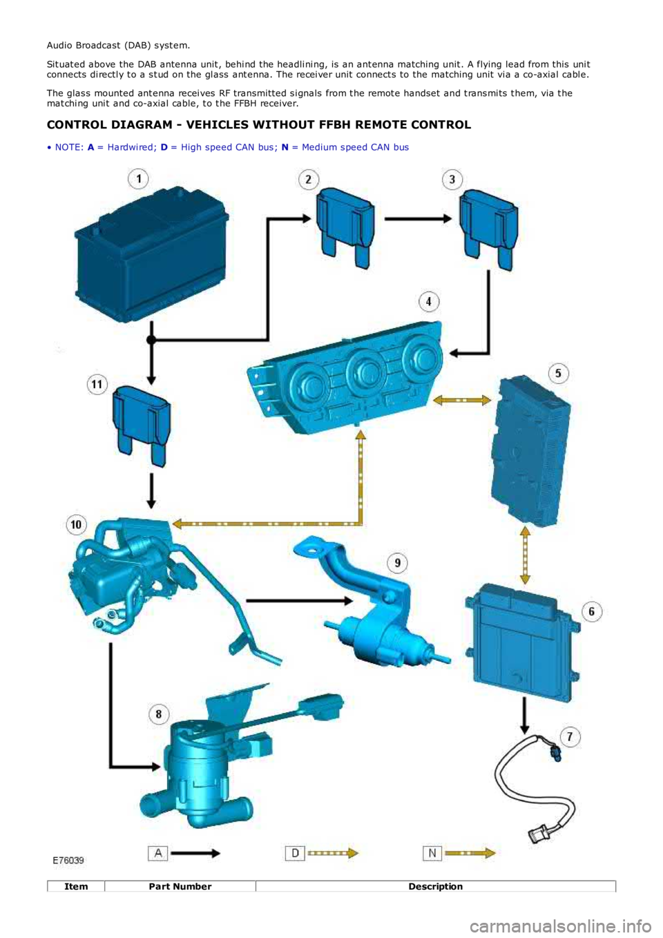
CONTROL DIAGRAM - VEHICLES WITHOUT FFBH REMOTE CONTROL
• NOTE: A = Hardwi red; D = High speed CAN bus ; N = Medium s peed CAN bus
ItemPart NumberDescription