2006 LAND ROVER FRELANDER 2 remote control
[x] Cancel search: remote controlPage 2059 of 3229
The pass i ve ant i-theft sys t em us es the foll owing component s:
Remote hands et trans ponderCJBECMStart cont rol moduleIns t rument clus terABS moduleElectric s t eering column lock (if enabl ed).
• NOTE: On North Ameri can Specificat ion (NAS) vehi cles , a running change was int roduced during 2008 Model Y ear (MY ) t odis able t he electric st eering col umn lock. Under t he change, the i nternal elect ronics (print ed circuit board (PCB), motor,etc.) of t he l ock have been removed and t he lock has been dis abled i n t he car configurat ion fi le. The change i sincorporat ed on VIN (vehi cl e identi fi cat ion number) 082896, 085531, 085622, 085685, 085832, 085891, 085942, 085987,086049, 086081, 086123, 086178, 086276, 086287, 086309, 086363, 086383, 086389, 086398, 086403 and 091770onwards .
The s ys t em i s automat ic and requi res no input from t he dri ver. The engi ne management s yst em wil l onl y allow engi necrank when an aut horizati on data mess age is received from t he CJB. The engi ne st art s ys tem is init iat ed when thes tart/s top s wi tch and t he brake pedal (automat ic t rans mis s ion) or t he cl utch pedal (manual trans mi ss i on) are pres s eds imul taneous l y.
The engi ne management s ys tem (ECM) wi ll only al low engi ne crank, s park (petrol models only) and inject or funct ions whent he foll owing condit ions are met:
A hardwi red Park/Neutral si gnal i s received from the Trans mi ss i on Cont rol Module (TCM) (aut omati c t ransmis s iononly)A hardwi red ignit ion s ignal is recei ved from t he CJBA hardwi red crank reques t s ignal is recei ved from t he CJBEncrypt ed data exchange bet ween t he ins trument cl ust er and the ECM is verifi ed.
Before the CJB will s end t he hardwired igni ti on si gnal , it mus t s ati s factori ly complet e t he fol lowi ng:
Exchanged encrypt ed data wit h the st art control modul e t o validat e t he remot e hands et .
Addit ional ly, before the CJB will s end t he hardwired crank reques t s ignal i t mus t receive t he fol lowing si gnal s:
Brake s ignal from t he brake s wi tch (automat ic t rans mis s ion) or clutch s i gnal from the clut ch s wit ch (manualt ransmis s ion)Hardwi red t rans mis s ion in Park (P) s ignal from t he s elector lever ass embl y (aut omatic trans mi s si on only).
CONTROL DIAGRAM
• NOTE: A = Hardwi red; D = High speed CAN bus ; N = Medium s peed CAN bus ; O = LIN bus ; W = LF t rans mis s ion
Page 2060 of 3229
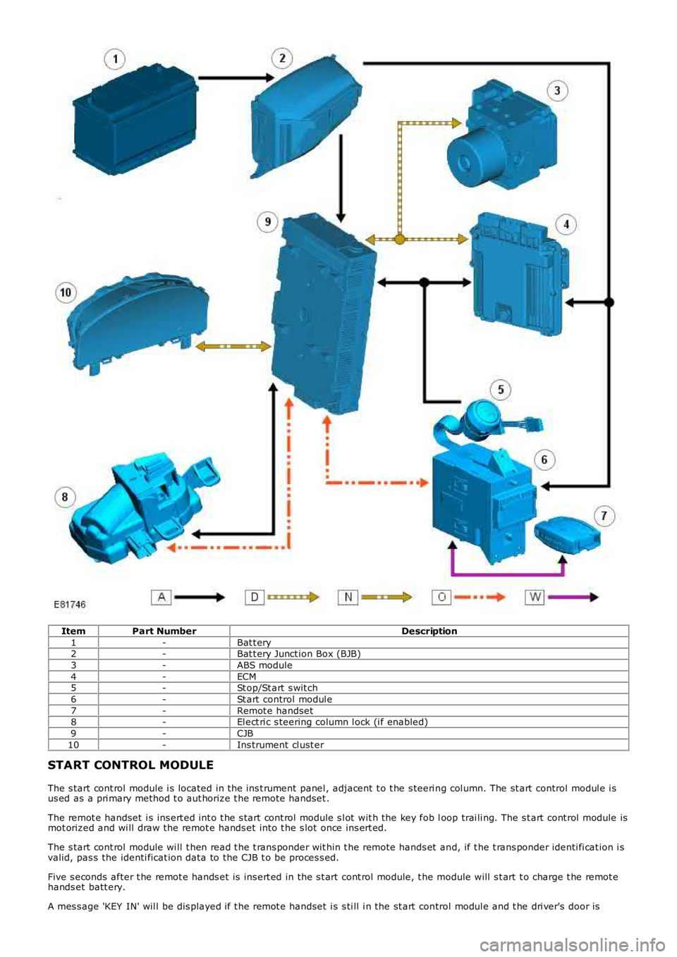
ItemPart NumberDescription
1-Bat t ery2-Bat t ery Junct ion Box (BJB)
3-ABS module
4-ECM5-St op/St art s wit ch
6-St art control modul e
7-Remot e handset8-El ect ri c s teering column l ock (i f enabled)
9-CJB
10-Ins trument cl ust er
START CONTROL MODULE
The s tart cont rol module i s located in t he ins t rument panel , adjacent t o t he s teeri ng col umn. The st art control modul e i sus ed as a pri mary method t o aut horize t he remot e handset .
The remot e handset i s ins ert ed int o t he s tart cont rol module s l ot wit h the key fob loop trai li ng. The s t art cont rol module ismot orized and wi ll draw the remot e hands et int o t he s lot once ins ert ed.
The s tart cont rol module wi ll t hen read t he t rans ponder wit hin t he remote hands et and, if t he t rans ponder identi fi cat ion i svalid, pas s the identi ficat ion data to the CJB t o be proces s ed.
Five s econds after t he remot e hands et is ins ert ed in the s t art cont rol module, t he module will s t art t o charge t he remot ehands et batt ery.
A mes s age 'KEY IN' wil l be dis played if t he remot e handset i s s ti ll i n the st art control modul e and t he dri ver's door is
Page 2061 of 3229
opened. The remot e handset i s removed from the st art control modul e by gentl y pushi ng the remote hands et int o t he st artcont rol module and releas ing. The s tart cont rol module mot or wil l then drive t he remot e hands et out from t he s lot as l ongas t he ignit ion i s off.
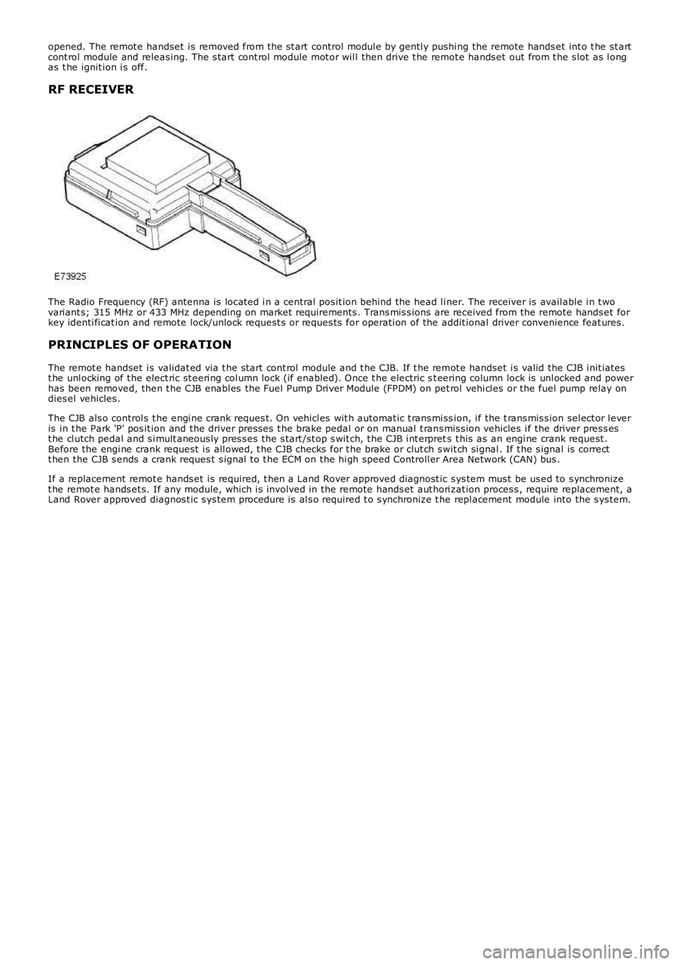
RF RECEIVER
The Radio Frequency (RF) antenna is locat ed i n a central pos it ion behind the head l iner. The receiver is avail able i n t wovariant s; 315 MHz or 433 MHz depending on market requirements . Trans mis s ions are received from the remote hands et forkey identi fi cat ion and remote lock/unlock request s or reques ts for operati on of the addit ional driver convenience feat ures.
PRINCIPLES OF OPERATION
The remot e handset i s validat ed via t he s tart cont rol module and t he CJB. If t he remot e handset i s valid the CJB i nit iatest he unl ocking of t he elect ric st eeri ng col umn lock (if enabled). Once t he electric st eering column lock is unl ocked and powerhas been removed, then t he CJB enabl es the Fuel Pump Dri ver Module (FPDM) on pet rol vehi cl es or the fuel pump relay ondies el vehicles .
The CJB als o control s t he engi ne crank reques t. On vehicl es wit h automat ic t rans mi ssion, i f the t rans mis s ion sel ect or l everis in t he Park 'P' pos it ion and the driver pres ses t he brake pedal or on manual t rans mis s ion vehicles i f the driver pres s est he cl utch pedal and s i mult aneous ly pres s es t he s tart /st op s wit ch, t he CJB i nt erprets t his as an engi ne crank request .Before the engi ne crank request i s all owed, t he CJB checks for t he brake or clut ch swit ch si gnal . If t he s ignal is correctt hen the CJB s ends a crank reques t s ignal t o t he ECM on the hi gh speed Controll er Area Network (CAN) bus .
If a replacement remot e hands et i s required, t hen a Land Rover approved diagnost ic sys tem mus t be us ed to s ynchronizet he remot e hands et s. If any module, which i s involved in the remote hands et aut hori zat ion proces s , require replacement, aLand Rover approved diagnos t ic s ys tem procedure is al s o required t o s ynchronize t he repl acement module into the s ys tem.
Page 2073 of 3229
ModuleNetw orkSystemFunctionVehicle Location
Integrat ed Cont rolModuleMedi umspeed CANbus
Contains controls for the ent ert ai nment sys t em andgateway between audio s ys t em and ot her vehicles ys t ems
Int egral part of head uni t,located i n cent re cons ole
Integrat ed Head Unit(IHU)Medi umspeed CANbus
Contains controls for the ent ert ai nment sys t emInt egral part of head uni t,located i n cent re cons ole
RH rear door moduleLINControl s wi ndow and locki ng operati onMount ed i n RH rear door
LH rear door moduleLINControl s wi ndow and locki ng operati onMount ed i n LH rear doorGenerat orLINProvide l oad s ignal t o ECMLocat ed in engine compart ment .Locat ion on engine dependenton engine fit ment.
RH front s eat heatmoduleLINUs ed by ATC t o cont rol s eat heat er temperat ureUnders ide of s eat
LH front s eat heatmoduleLINUs ed by ATC t o cont rol s eat heat er temperat ureUnders ide of s eat
Air quali ty sens orLINMeasures air qualit y i n t he vehi cl e int eri orFit ted t o t he heater as sembl y
Flap act uat or modul e 1LINMoves fl aps wit hi n t he heat er ass embl y to direct airfl ow t o different parts of t he i nt eri orPart of t he heat er as s embly
Flap act uat or modul e 2LINMoves fl aps wit hi n t he heat er ass embl y to direct airfl ow t o different parts of t he i nt eri orPart of t he heat er as s embly
Flap act uat or modul e 3LINMoves fl aps wit hi n t he heat er ass embl y to direct airfl ow t o different parts of t he i nt eri orPart of t he heat er as s embly
Flap act uat or modul e 4LINMoves fl aps wit hi n t he heat er ass embl y to direct airfl ow t o different parts of t he i nt eri orPart of t he heat er as s embly
Flap act uat or modul e 5LINMoves fl aps wit hi n t he heat er ass embl y to direct airfl ow t o different parts of t he i nt eri orPart of t he heat er as s embly
Humi di ty sens orLINMeasures air qualit y i n t he vehi cl e int eri orInt egral wit h t he int eri or rearview mirror
HVAC control modul eLINControl s operat ion of t he HVAC s ys t em funct ionsInt egral wit h HVAC controlspanel i n cent re cons ole
St eering wheel moduleLINConverts analogue s ignals from s teering wheels wit ches i nto di git al mes s agesBehi nd s teering wheelclocks pri ngBatt ery backed s ounderLINActi vat ed by CJB when alarm t ri gger i s receivedMount ed i n a central pos it ionbetween t he bulkheads i n t heengi ne compartment
Electric st eeringcolumn l ockLINControl s t he locking and unlocki ng of the st eeri ngcol umnOn unders ide of s t eeringcol umn, under lower columns hroud
CJBLINControl body funct ions and power di st ributi onPass enger footwell , behi ndglovebox
Light s wit ch moduleLINControl of headlamp operat ion and l evel lingDri ver's s i de of ins trument panelVolumet ri c s ens orLINDetects movement i n vehicle i nterior and act ivatesanti -t heft alarm s ys temIn hous ing in centre ofheadl ining
Rain sens or modul eLINDetects mois t ure on t he wi nds hiel dAt top of windshi el dSt art cont rol unitLINUs ed to identi fy t he remote hands et - component oft he keyles s s t art s yst emIn ins trument panel, adjacent tothe st eeri ng col umnRF recei verLINRecei ves RF trans mi s si ons from t he TPMS s yst emand t he remot e hands etPosi ti oned adjacent t o the rearint erior l amp, behi nd theheadl ining
Headlamp l evel li ngmoduleLINControl s t he dynami c headl amp l evell ing funct ionsPass enger footwell , behi ndglovebox, int egral wit hheadl amp levell ing module
RH headlampLINProvides pos it ional i nformati on to the headlamplevell ing moduleAtt ached t o t he headl ampass embl y
LH headlampLINProvides pos it ional dat a t o t he headlamp levell ingmoduleAtt ached t o t he headl ampass embl y
Driver's window s wi tchLINControl s operat ion of t he driver's wi ndowMount ed i n dri ver's door
Driver's door moduleLINControl s wi ndow and locki ng functi onsMount ed i n dri ver's doorPas senger door moduleLINControl s wi ndow and locki ng functi onsMount ed i n pass enger door
Trans mi ss ion sel ect orl ever moduleLINSends sel ect or l ever pos it ion t o t he TCMLocat ed bel ow centre cons ole
TCMLINRecei ves s elect or l ever pos it ion i nformat ion tocont rol t rans mis s ion operat ionMount ed on t he t op of thetransmis s ion housi ngIntegrat ed Cont rolModuleMOSTContains controls for the ent ert ai nment sys t em andgateway between audio s ys t em and ot her vehicles ys t ems
Int egral part of head uni t,located i n cent re cons ole
Integrat ed Head UnitMOSTContains controls for the ent ert ai nment sys t emInt egral part of head uni t,located i n cent re cons oleDi gi tal Audio Broadcas t(DAB) recei verMOSTRecei ves di git al radi o broadcast sMount ed i n LH s ide of t heluggage compartmentBluet oot h phonemoduleMOSTControl s t he operati on of the Bl uet ooth phones ys t emMount ed i n RH s i de of theluggage compartment
Ampl ifi er/TunerMOSTProvides ampl ifi cat ion for the ent ert ainments ys t ems and recepti on of radio RF broadcas t sMount ed i n RH s i de of theluggage compartment
Navigati on comput erMOSTReads map data from a DVD t o cal cul ate and di spl ayvis ual route gui dance i nformat ion vi a t he TAD andaudi ble gui dance via the ampl ifier to the driver
Below t he IHU i n t he cent recons ole
Page 2124 of 3229
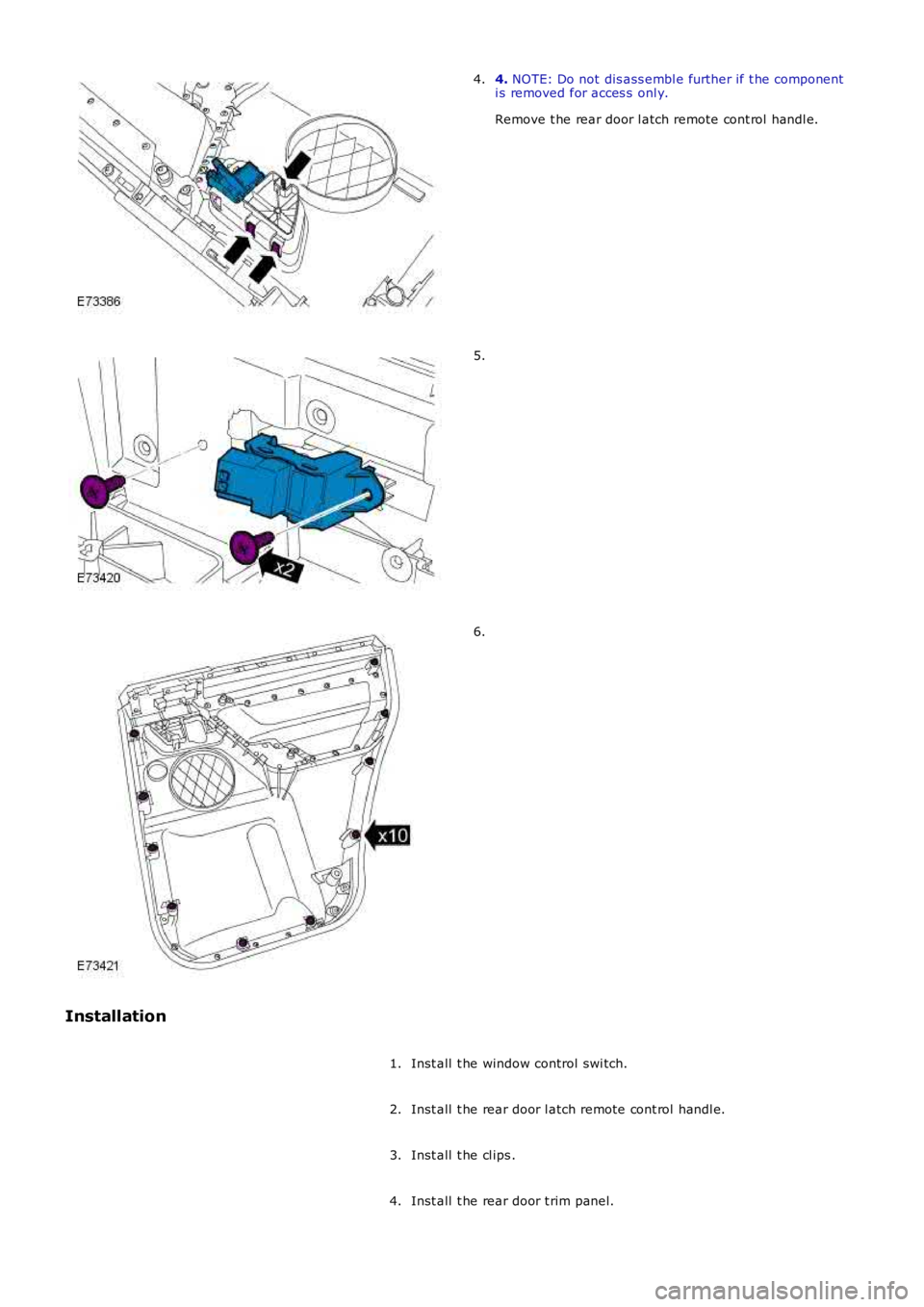
4. NOTE: Do not dis ass embl e further if t he componenti s removed for acces s onl y.
Remove t he rear door l atch remote cont rol handl e.
4.
5.
6.
Installation
Inst all t he window control swi tch.1.
Inst all t he rear door l atch remote cont rol handl e.2.
Inst all t he cl ips .3.
Inst all t he rear door t rim panel.4.
Page 2161 of 3229
(Ignit ion). The forward facing light s ensor moni tors the ambi ent light l evel at the front of t he vehi cl e; the rearward facingli ght sens or moni tors t he li ght l evel coming from t he rear of the vehicle. W hen li ght from the rear of the vehicle exceedst he ambient li ght l evel from the front of t he vehi cl e, the aut omat ic di mmi ng circuit darkens t he i nt eri or mirror s urface.
Automat ic di mmi ng is i nhi bit ed when revers e gear is sel ect ed to provide t he dri ver wi th maximum vis ion. On vehicles wi thautomat ic t rans mis s ion, t he revers e gear s ignal i s provided by t he TCM vi a t he high s peed Cont rol ler Area Net work (CAN)bus to the CJB. The CJB then provi des a power feed t o t he mirror. On vehicles wi th manual t rans mis s ion, the revers e gears ignal is provi ded by a t ransmis s ion s wit ch t hat i s hardwi red t o t he CJB.
Cabin Humidity Sensor
Dependi ng on the vehicl e s pecificati on, t he automat ic di mmi ng int erior mirror may als o i ncorporate a cabi n humidi tys ens or. The cabin humi dit y s ens or is locat ed i n the mirror rear cas ing near to the wi nds hiel d, and provi des the ATC modul ewit h i nformati on regarding the probabil it y of winds hield mis t ing. Thi s i nformat ion is us ed to vary t he automat ic operat ionof the cl imat e cont rol s yst em.For addit ional informat ion, refer t o: Cont rol Component s (412-01 Cli mat e Cont rol , Descripti on and Operat ion).
EXTERIOR MIRRORS
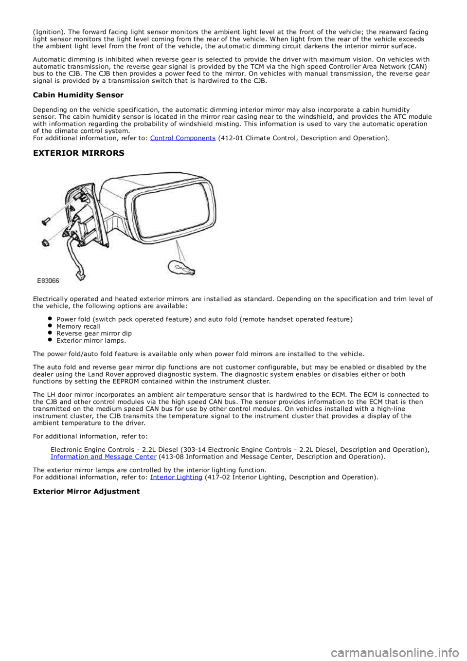
Electricall y operated and heated ext eri or mirrors are i nst all ed as s tandard. Depending on the s pecifi cat ion and trim level oft he vehi cl e, t he followi ng opti ons are available:
Power fold (s wit ch pack operat ed feat ure) and auto fol d (remote hands et operated feature)Memory recallRevers e gear mirror dipExteri or mirror l amps.
The power fold/aut o fold feature is avail abl e only when power fol d mi rrors are i ns t alled to t he vehicle.
The auto fold and revers e gear mirror dip functi ons are not cus t omer confi gurable, but may be enabled or dis abled by t hedeal er usi ng the Land Rover approved di agnos ti c s ys t em. The diagnos t ic s ys tem enabl es or di sabl es ei ther or bothfuncti ons by s et t ing t he EEPROM cont ained wi thin the ins trument cl us t er.
The LH door mirror i ncorporat es an ambi ent ai r temperat ure sens or that is hardwired to the ECM. The ECM is connected tot he CJB and ot her cont rol modules via the hi gh s peed CAN bus . The s ensor provides i nformati on to the ECM that is thent ransmit ted on the medi um s peed CAN bus for us e by ot her control modul es. O n vehi cl es ins tal led wi th a high-lineins t rument clus ter, t he CJB t rans mit s t he temperature s ignal t o t he ins t rument clus ter t hat provi des a dis play of t heambient t emperature t o the driver.
For addit ional informat ion, refer t o:
Elect roni c Engi ne Cont rol s - 2.2L Dies el (303-14 Electronic Engine Controls - 2.2L Dies el, Des cript ion and Operat ion),Informat ion and Mes s age Cent er (413-08 Informati on and Mes sage Cent er, Descripti on and Operat ion).
The exteri or mirror l amps are controll ed by the interior li ght ing funct ion.For addit ional informat ion, refer t o: Int eri or Li ght ing (417-02 Interior Lighti ng, Des cri pt ion and Operati on).
Exterior Mirror Adjustment
Page 2163 of 3229
Revers e gear mirror dip i s only avail abl e when memory mi rrors are ins t al led, and revers e gear mi rror di p is enabled wit hint he ins trument cl ust er.
If the driver sel ect s a memory recall funct ion us ing the memory s eat swit ch pack, the driver's memory seat and exteriormemory mi rrors are moved to a s tored memory pos i ti on.For addit ional informat ion, refer t o: Seat s (501-10 Seati ng, Des cript ion and Operat ion).
Mirror Power Fold and Auto Fold Feature
Exteri or mirrors wit h t he power fold/auto fold feature incorporat e a motor located in t he hinge of each ext eri or mirror arm.Operat ion of t he power fold feature is achieved us ing t he exteri or mirror s wit ch pack. Operat ion of t he auto fold feature isachi eved us ing the remote hands et.
The power fold funct ion is acti ve when t he ignit ion i s in power mode 6 (Ignit ion).
Both ext eri or mirrors wil l power fol d when t he mi rror s wi tch pack 'L' and 'R' s wit ches are pres s ed t oget her. Pres s ing t hes wit ches again wil l unfol d t he mi rrors .
W hen t he i ns t rument clus ter i s configured for the aut o fol d feat ure, t he mirrors wi ll fol d in when the remot e hands et lockbutt on is pres sed. The mi rrors wi ll unfold when the vehicl e is unl ocked us ing t he remot e handset unlock butt on.
• NOTE: If the mirrors are folded in usi ng t he mirror s wit ch pack (power fol d) and the vehicle i s t hen locked, s ubs equentunlocki ng of the vehicle wil l not unfol d t he mirrors .
W hen t he remote hands et unl ock but ton i s operated, t he CJB recogni zes t he remote hands et for that vehicle andacknowledges t he request . The door control modul es are connect ed direct ly t o t he AJB for power s uppl y to the ext eriormi rror folding motors.
W hen t he vehicle i s locked the door cont rol modules revers e t he pol ari ty of t he mi rror fold motor, power and groundconnecti ons to operat e t he mi rrors i n t he oppos it e direct ion.
Exterior Mirror Heating
Exteri or mirror heati ng is provi ded wit h heater element s bonded to t he back of the mirror glas s. Power s uppl y for t he mi rrorheat ing el ements i s provided by the corresponding driver or pas s enger door control modul e via the AJB.
The door control modul es receive a power s uppl y from the AJB, and are bot h connected on the medi um s peed CAN bus t ot he ATC module. A ground t erminal from each door control modul e completes the circuit. The ATC modul e automat icall ycont rol s the mirror heati ng functi on whenever the ignit ion i s in power mode 4 (Access ory) and power mode 6 (Igni ti on).For addit ional informat ion, refer t o: Cont rol Component s (412-01 Cli mat e Cont rol , Descripti on and Operat ion).
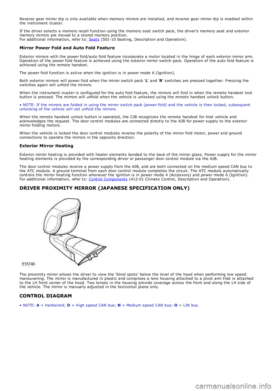
DRIVER PROXIMITY MIRROR (JAPANESE SPECIFICATION ONLY)
The proximit y mirror al lows t he dri ver t o view the 'blind spot s' below the l evel of t he hood when performing low s peedmaneuvering. The mirror i s manufactured in pl ast ic and compris es a l ens hous ing at tached to a pivot arm t hat i s att achedt o the LH front corner of t he hood. Two l enses i n t he hous i ng provide coverage across the front and along t he LH s i de oft he vehi cl e. The mirror is manual ly adjus t ed in the hori zont al pl ane only.
CONTROL DIAGRAM
• NOTE: A = Hardwi red; D = Hi gh s peed CAN bus ; N = Medi um s peed CAN bus; O = LIN bus .
Page 2174 of 3229
3
-Remote hands et
4 -Start control modul e
5 -Rear pas senger s eat s
6 -Auxi liary Junct ion Box (AJB)
7 -Dri ver's door lat ch and ajar s wit ch
8 -Dri ver's s eat manual operat ed lumbar s upport
9 -Power operat ed lumbar s upport air cel ls
10 -Dri ver's s eat power operat ed lumbar s upport motor
11 -Dri ver's power operated s eat s quab recline motor
12 -Power operat ed lumbar s upport swit ch
13 -Dri ver's power operated s eat height motor
14 -Dri ver's power operated non-memory s eat s wit ch pack
15 -Dri ver's power operated memory s eat s wit ch pack
16 -Dri ver's power s eat modul e (memory)
17 -Dri ver's s eat heat ing modul e
18 -Dri ver's s eat cus hion/squab heati ng element
19 -Pas s enger power operated s eat s quab recl ine motor
20 -Dri ver's and pas senger power operat ed s eat s l ide mot or
21 -Pas s enger s eat heat ing modul e
22 -Pas s enger s eat occupancy clas s ifi cat ion sens or
23 -Pas s enger s eat cus hion/s quab heati ng element
24 -Pas s enger power operated s eat non-memory s wit ch pack
25 -Pas s enger s eat occupancy detecti on s ens or
26 -Dri ver's s eat pos i ti on s ens or
27 -Cent ral Junct ion Box (CJB)
OVERVIEW
All vehicles , except thos e manufactured to Nort h American Specificati on (NAS), are i ns tall ed wit h manuall y operated front
s eat s as s t andard. Opt ions available include electricall y power operat ed front s eat s wi thout memory functi on, and an
electricall y power operat ed dri ver's s eat wit h memory funct ionalit y. The front s eats may als o be provi ded wit h arm rest s t o
improve dri ver and front pass enger comfort .
NAS vehicles are ins tal led wi th power operat ed front seat s as s tandard. The front se at s feat ure arm res ts t o i mprove driver
and front pas s enger comfort. A dri ver's power operated s eat wit h memory funct ionalit y i s provided as an opt ion for NAS
vehi cl es.
Dependi ng on vehi cl e s peci fi cat ion and t ri m l evel , vehi cl es may als o feature front h eat ed s eat s and a l umbar support
s ys t em. Lumbar s upport is provided as a manual or electrically operat ed s yst em, and i s onl y available for t he dri ver's s eat.
The rear s eat is manufact ured t o t he s ame s pecificati on for al l vehicles , and is pro vided wi th ISOFIX chi ld s afet y s eat
res t raint s .
All s eats i ncorporate adjust able head rest rai nt s . Depending on the vehicle specifica ti on the seat s are uphols t ered in eit her
all clot h, cl ot h/l eat her/PVC, l eather/PVC or all PVC finis h.
FRONT SEAT CONSTRUCTION
The front seat bas e is manufact ured from high s t rength st eel ext rus ions des igned to exceed current l egal s trengt h
requirements . The s eat bas e i s molded t o form an anti -s ubmari ne hollow that wi ll ret ain t he occupant in the s eat during a
front end col lis i on. The s eat backres t is manufact ured from high st rength s teel and features a wi re sus pens i on sys t em t o
provide i ncreased comfort . The backres t is at t ached at both si des of t he s eat bas e w it h a high st rengt h s teel bracket and
pivot.
The s eat bas e and backrest are i nl ayed wit h formed s ect ions of dual hardnes s , molded foam t o form the s eat s quab and
cus hion. The s eats are desi gned to provide s upport, comfort and an ergonomic pos it io n for t he driver and pass enger.
The dri ver and pas senger front seat s are provi ded wit h addit ional safet y feat ures . T he front driver's s eat is i nst all ed wit h a
s eat pos it ion s ens or; t he front pas s enger s eat is i ns t alled wit h an occupancy cl ass i ficati on s yst em s ens or (dependant on
vehi cl e s peci fi cat ion) and an occupancy det ect ion s ys tem. Bot h t he driver's and pas s enger seat s afet y feat ures provide
inputs to cont rol the deployment of the ai r bags and seat belt pre-t ens ioners .
For addit ional informat ion, refer t o: Air Bag and Safet y Belt Pretens ioner Supplement al Res traint Syst em (SRS) (501-20B
Suppl ement al Rest rai nt Sys tem, Des cri pti on and Operati on).
The front seat belt buckl es are mount ed i nt egrall y wi th t he s eats t o provi de increas ed anchorage and occupant res t raint .
For addit ional informat ion, refer t o: Safety Bel t Syst em (501-20A Safet y Belt Sys tem, Des cript ion and O perati on).
MANUALLY OPERATED FRONT SEATS