2006 LAND ROVER FRELANDER 2 warning
[x] Cancel search: warningPage 2911 of 3229
191
Wheels and tyres
R
12. During the inflation, switch the
compressor off briefly to check the tyre
pressure using the gauge mounted on the
compressor.
• It should not take longer than seven
minutes to inflate the tyre. If after seven
minutes the tyre ha s not reached the
minimum pressure, the tyre should not
be used.
13. Once the tyre has been inflated switch off
the compressor. If desired the engine may
be turned off after the compressor has
been turned off.
14. Remove the power connector from the
auxiliary power socket.
15. Remove the inflation hose from the tyre
valve by unscrewing it as quickly as
possible (anti-clockwise).
16. Replace the inflation hose protective cap,
and the tyre valve cap.
17. Do not remove the sealant bottle from the
receiver.
18. Ensure that the tyre repair kit (including
the bottle, and receiver caps) are placed
securely in the vehicle. You will need to
use the kit to check the tyre pressure after
3km (2 miles) so ensure they are easily
accessible.
19. Immediately drive the vehicle for 3 km (2
miles) to allow the sealant to coat the inner
surface of the tyre and form a seal at the
puncture.
†When pumping the sealant through the tyre
valve, the pressure may rise up to 6 bar (87
lb/in²). The pressure will drop again after
approximately 30 seconds.
Checking the tyre pressure after a repair
1. Drive the vehicle for 3 km (2 miles) then
stop in a safe place. Carry out a visual
examination of the tyres condition.
2. Remove the protective cap from the
inflation hose.
3. Screw the inflation hos e connector firmly
onto the tyre valve.
4. Read the tyre pressure from the gauge.
5. If the pressure of the sealant filled tyre is
above 1.3 bar (19 lb/in²) adjust the
pressure to the correct value. See
TECHNICAL SPECIFICATIONS (page 194).
6. Ensure that the compressor switch is in
the off position ( O), and insert the power
cable connector into an auxiliary power
socket. See AUXILIARY POWER
SOCKETS (page 110).
7. If the vehicle is in a well ventilated area,
start the engine.
8. Switch on the compressor ( I), and inflate
the tyre to the correct pressure.
WARNINGS
When driving the vehicle, if you
experience vibr ations, abnormal
steering, or noises, re duce speed immediately.
Drive with extreme caution and reduced speed
to the first safe place to stop the vehicle.
Visually examine the tyre, and check it's
pressure. If there are any signs of damage or
deformity to the tyre, or the tyre pressure is
below 1.3 bar (19 lb/i n²) do not continue
driving.
Consult a tyre repair centre, or your
Land Rover Dealer/Authorised repairer
for advice concerning the replacement of a
tyre after using a tyre repair kit.
Page 2912 of 3229
Wheels and tyres
192
L
9. To check the tyre pressure turn off the
compressor then read the pressure from
the gauge.
10. When the compressor is off, if the tyre
pressure is too high, release the required
amount of pressure using the pressure
relief valve.
11. Once the tyre is inflated to the correct
pressure, switch off the compressor and
remove the power plug from the auxiliary
socket.
12. Unscrew the inflation hose connector from
the tyre valve, replace the tyre valve cap
and the inflation hose connector protective
cap.
13. Do not remove the sealant bottle from the
receiver.
14. Ensure that the tyre repair kit (including
the bottle, and receiver caps) are placed
securely in the vehicle.
15. Drive to the nearest tyre repair centre, or
Land Rover Dealer/Autho rised repairer for
a replacement tyre to be fitted. Ensure that
you make the repair centre aware that the
tyre repair kit has been used before the tyre
is removed.
16. Both the tyre inflation hose, and the sealant
bottle should be replac ed once a new tyre
has been fitted.
Only sealant bottles which are
completely empty should be
disposed of with normal household
waste. Sealant bottles which contain some
sealant, and the tyre in flation hose, should be
disposed of by a tyre specialist, or your Land
Rover Dealer/Authorised repairer in
compliance with local waste disposal
regulations.USING SNOW CHAINS
Land Rover approved trac tion devices may be
used to improve traction on a hard road surface
in heavy snow conditions . They should not be
used in off-road conditions.
If it becomes necessary to fit traction devices,
the following points should be observed:-
• Single sided Spike-spyder traction devices
can only be fitted to the front wheels of
vehicles fitted with 17 or 18 inch diameter
wheels.
• The wheels and tyres fitted must
conform to the specifications of the
original equipment.
• No traction devices should be fitted to the
rear wheels.
• Only Land Rover approved traction devices
should be used on the vehicle. Only Land
Rover approved tracti on devices have been
tested to ensure that they do not cause
damage to the vehicl e. Contact your Land
Rover Dealer/Authorised repairer for
information.
• Always read, understa nd, and follow the
snow chain manufacturer's instructions.
Pay particular attention to the maximum
speed, and fitti ng instructions.
WARNING
Only use traction devices in heavy snow
conditions, on hard road surfaces.
Dynamic Stability Control (DSC) must be
switched off when using traction devices. DSC
limits wheel spin which is required to maintain
traction in deep snow conditions.
Never exceed 50 km/h (30 mph) when traction
devices are fitted.
Never fit traction devices to a temporary use
spare wheel.
Page 2914 of 3229
Wheels and tyres
194
L
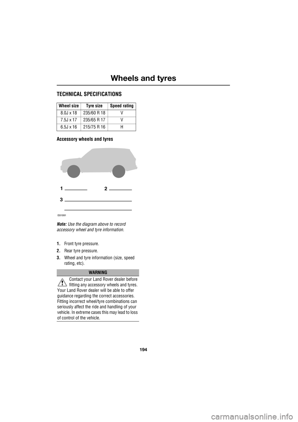
TECHNICAL SPECIFICATIONS
Accessory wheels and tyres
Note: Use the diagram above to record
accessory wheel and tyre information.
1. Front tyre pressure.
2. Rear tyre pressure.
3. Wheel and tyre information (size, speed
rating, etc).
Wheel size Tyre size Speed rating
8.0J x 18 235/60 R 18 V
7.5J x 17 235/65 R 17 V
6.5J x 16 215/75 R 16 H
WARNING
Contact your Land Rover dealer before
fitting any accessory wheels and tyres.
Your Land Rover dealer wi ll be able to offer
guidance regarding the correct accessories.
Fitting incorrect wheel/tyre combinations can
seriously affect the ride and handling of your
vehicle. In extreme cases this may lead to loss
of control of the vehicle.
12
3
E81991
Page 2924 of 3229
Emergency equipment
204
L
Emergency equipmentHAZARD WARNING FLASHERS
If the vehicle is stationary in an unsafe location,
or may cause a hazard to other road users,
switch on the hazard warning flashers. Press
the switch to turn the hazard warning lamps
on.
Note: Hazard warning lamps can be used when
the ignition is on or off.
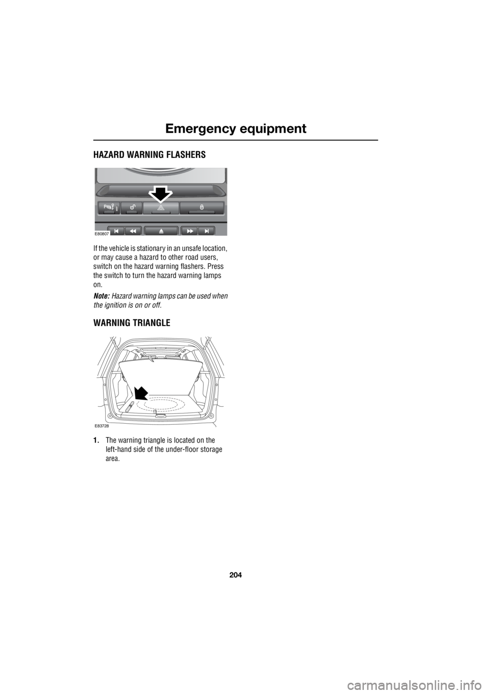
WARNING TRIANGLE
1. The warning triangle is located on the
left-hand side of the under-floor storage
area.
E80807
E83728
Page 2925 of 3229
205
Status after a collision
R
Status after a collisionDRIVING AFTER A COLLISION
Before starting or driving
If the vehicle has been involved in an accident
it should be checke d thoroughly before
attempting to start the engine or drive the
vehicle.
Check for :-
• Fuel leaks.
• Fluid leaks.
• Battery damage.
• Damage to wiring.
• Damage to lights.
• Damage to steering, suspension, wheels
or tyres.
• Sharp or protruding bodywork.
• Operation of doors and locks.
• Condition and operation of seat belts and
SRS components.
• Condition of chil d seats and their
mounting/attach ment points.
Note: This list is not exhaustive.
Resetting the fuel cut-off
The fuel system cut-off forms part of the Safety
and Restraint System (SRS) fitted to your
vehicle. Following an im pact, and depending on
the severity, the fuel pump may be switched
off.
1. Switch the ignition off, and wait for one
minute.
2. Turn the ignition on for 30 seconds.
3. Check the vehicle thoroughly for fuel leaks.
If a leak is detected switch the ignition off
immediately.
• The vehicle must not be started if a leak
is present. Seek qualified advice, and
have the vehicle recovered.
4. If no leaks are detected, start the vehicle.
When driving
When driving a vehicle which has been
involved in a collision use caution and pay extra
attention to the operation of the vehicle. If any
changes in vehicle operati on after the collision
are noted when compared to it's operation
before the collision, do not continue to drive
the vehicle. Stop the vehicle as soon as it is
safe to do so, and have the vehicle recovered.
Pay particular attent ion to changes in :-
• Steering.
• Braking.
• Unusual noises.
• Warning lights or messages displayed.
• Problems with electrical systems.
WARNING
If the vehicle is involved in a collision it
should be checked by a Land Rover
Dealer/Authorised repairer, or suitably
qualified persons before starting or driving.
WARNING
The fuel cut-off s hould never be reset
if you can smell fuel , or a leak can be
seen. Doing so can lead to a fire which
may cause personal injury or death.
Page 2926 of 3229
Status after a collision
206
L
INSPECTING SAFETY SYSTEM
COMPONENTS
Following a collision the seat belt and
Supplementary Restrain t System components
should be inspected for damage and/or
deformity. The inspection and any subsequent
repair work should only be carried out by a
Land Rover Dealer/Authorised Repairer, or
other suitably qualified persons.
Components which require inspection include
:-
• Seat belt webbing and mechanisms.
• Seat belt pr e-tensioners.
• Airbag covers and modules.
• Seat frames and mounting points.
• Child seats.
• Child seat anchor points.
Note: This list is not exhaustive.
In addition to the physical items checked the
electronic control system and it's associated
wiring should also be checked thoroughly. This
process will include a diagnostic check which
can only be carried out by a Land Rover
Dealer/Authorised repairer or suitably qualified
and equipped persons.
WARNING
It is not recommended that the vehicle
be driven or used until all of the
occupant protecti on systems have
been checked.
Page 2927 of 3229
207
Vehicle recovery
R
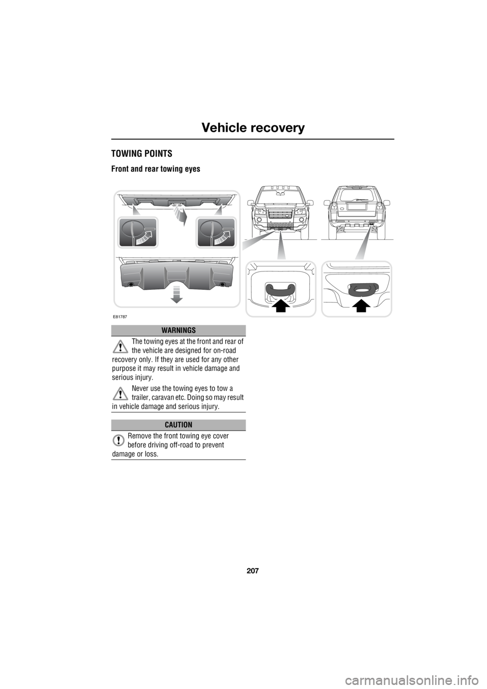
Vehicle recoveryTOWING POINTS
Front and rear towing eyes
E81787
WARNINGS
The towing eyes at the front and rear of
the vehicle are designed for on-road
recovery only. If they are used for any other
purpose it may result in vehicle damage and
serious injury.
Never use the towing eyes to tow a
trailer, caravan etc. Doing so may result
in vehicle damage and serious injury.
CAUTION
Remove the front towing eye cover
before driving off-road to prevent
damage or loss.
Page 2928 of 3229
Vehicle recovery
208
L
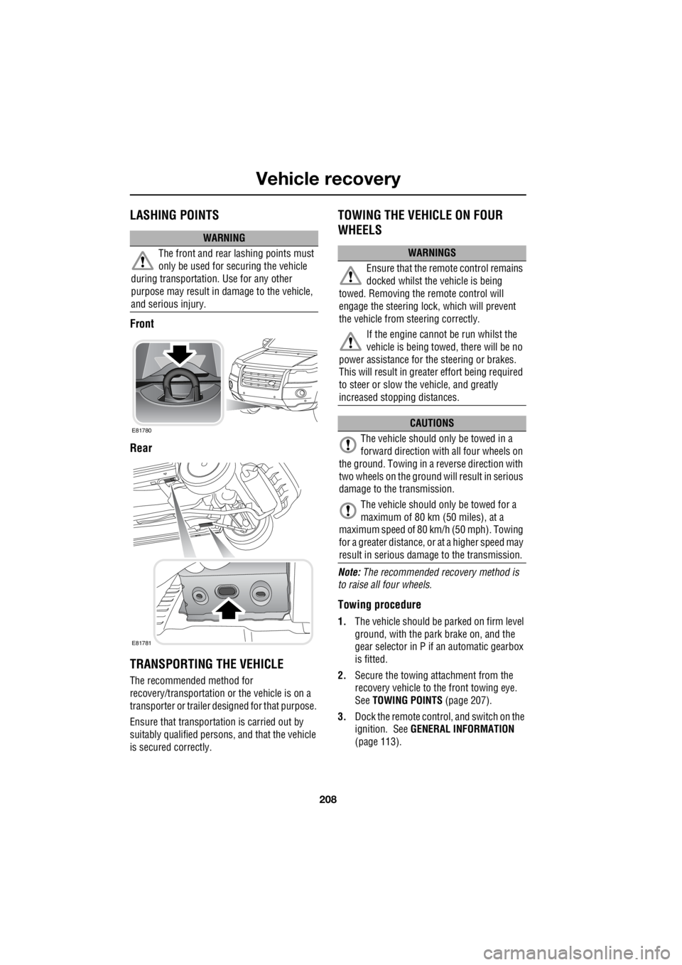
LASHING POINTS
Front
Rear
TRANSPORTING THE VEHICLE
The recommended method for
recovery/transportation or the vehicle is on a
transporter or trailer de signed for that purpose.
Ensure that transporta tion is carried out by
suitably qualified persons , and that the vehicle
is secured correctly.
TOWING THE VEHICLE ON FOUR
WHEELS
Note: The recommended recovery method is
to raise all four wheels.
Towing procedure
1. The vehicle should be parked on firm level
ground, with the park brake on, and the
gear selector in P if an automatic gearbox
is fitted.
2. Secure the towing attachment from the
recovery vehicle to the front towing eye.
See TOWING POINTS (page 207).
3. Dock the remote control, and switch on the
ignition. See GENERAL INFORMATION
(page 113).
WARNING
The front and rear lashing points must
only be used for securing the vehicle
during transportation. Use for any other
purpose may result in da mage to the vehicle,
and serious injury.
E81780
E81781
WARNINGS
Ensure that the remote control remains
docked whilst the vehicle is being
towed. Removing the remote control will
engage the steering lo ck, which will prevent
the vehicle from steering correctly.
If the engine cannot be run whilst the
vehicle is being towed, there will be no
power assistance for the steering or brakes.
This will result in grea ter effort being required
to steer or slow the vehicle, and greatly
increased stopping distances.
CAUTIONS
The vehicle should only be towed in a
forward direction with all four wheels on
the ground. Towing in a reverse direction with
two wheels on the ground will result in serious
damage to the transmission.
The vehicle should only be towed for a
maximum of 80 km (50 miles), at a
maximum speed of 80 k m/h (50 mph). Towing
for a greater distance, or at a higher speed may
result in serious dama ge to the transmission.