2006 LAND ROVER FRELANDER 2 wheel bolt torque
[x] Cancel search: wheel bolt torquePage 1370 of 3229
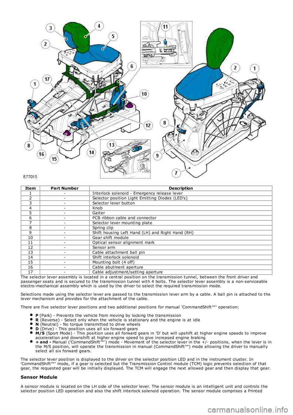
ItemPart NumberDescription
1-Interlock sol enoi d - Emergency rel eas e l ever2-Selector pos it ion Light Emi tt ing Di odes (LED's )
3-Selector l ever butt on
4-Knob5-Gait er
6-PCB ribbon cabl e and connector
7-Selector l ever mounti ng plat e8-Spri ng clip
9-Shift hous i ng Left Hand (LH) and Ri ght Hand (RH)
10-Gear s hi ft modul e11-Opt ical sens or al ignment mark
12-Sensor arm
13-Cable at t achment ball pin14-Shift int erlock s olenoid
15-Mounti ng bolt (4 off)
16-Cable abut ment aperture17-Cable adjust ment/s ett ing apert ure
The s elect or lever ass embly is l ocat ed in a cent ral posi ti on on t he t ransmis s ion t unnel , bet ween the front driver andpass enger s eats and is s ecured t o t he transmis si on t unnel wit h 4 bol ts . The s elector lever ass embly is a non-s erviceabl eelectro-mechani cal as s embly whi ch is us ed by t he dri ver t o s elect the requi red t ransmi ss i on mode.
Selecti ons made usi ng the sel ect or lever are pass ed t o t he t rans mis s ion l ever arm by a cable. A bal l pi n i s att ached t o t helever mechanis m and provides for the at tachment of t he cable.
There are fi ve s elect or lever pos i ti ons and t wo addit ional pos i ti ons for manual 'CommandShi ft ™' operati on:
P (Park) - Prevents t he vehicle from moving by locki ng the trans mi ss i onR (Revers e) - Sel ect only when the vehicle is s t ati onary and the engi ne is at i dleN (Neutral) - No torque trans mi tt ed t o dri ve wheel sD (Drive) - Thi s pos it ion us es all s ix forward gearsM/S (Sport Mode) - This pos it ion us es all forward gears in 'D' but wil l ups hift at hi gher engine s peeds to improveaccelerati on and downs hift at higher engine speed t o give i ncreased engine braki ng+ and - Manual ('CommandShi ft ™') mode - Movement of t he s elector lever in the +/- posi ti ons, when t he l ever is int he M/S pos i ti on, wi ll operate the trans mi ss i on in manual (CommandShift ™) mode all owing t he dri ver t o manuall ys elect al l si x forward gears.
The s elect or lever pos i ti on is di spl ayed t o t he dri ver on the s elector pos it ion LED and i n t he ins trument cl ust er. In'CommandShift™ ' mode, i f a gear i s s elected but t he Trans mis s ion Control modul e (TCM) logic prevent s s el ect ion of t hatgear, t he request ed gear will be init iall y dis played. The TCM wil l engage t he next al lowed gear and then di spl ay that gear.
Sensor Module
A s ens or modul e is locat ed on t he LH s ide of t he s elector lever. The s ens or modul e is an int el li gent unit and controls t hes elect or posi ti on LED operati on and als o t he s hift interlock s olenoi d operat ion. The sens or modul e compri ses a Pri nt ed
Page 1401 of 3229
from the clut ch pedal .
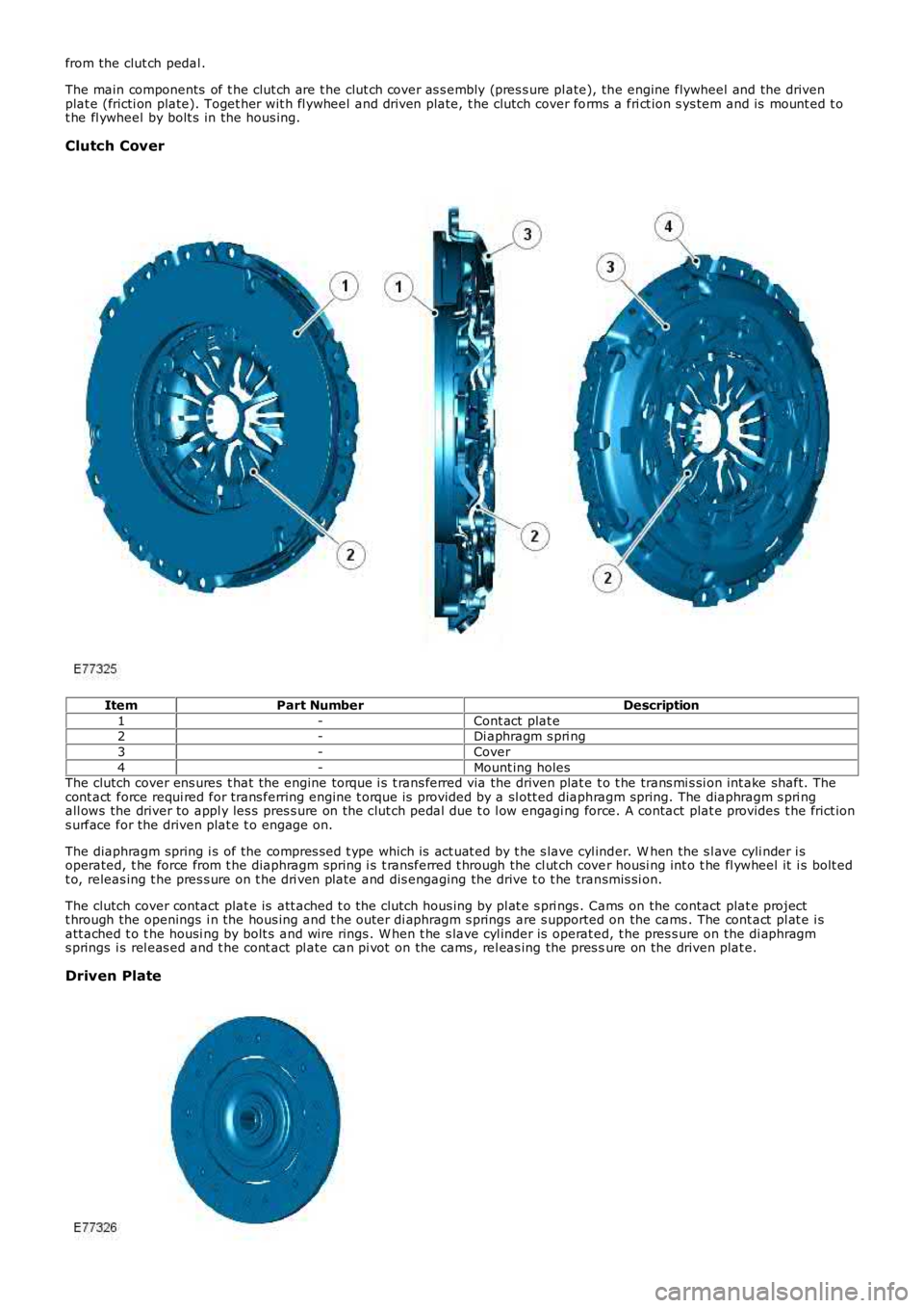
The main components of t he clut ch are t he clut ch cover as s embly (pres s ure pl ate), the engine flywheel and the drivenplat e (fricti on plate). Toget her wit h fl ywheel and dri ven plate, t he clutch cover forms a fri ct ion s ys tem and is mount ed t ot he fl ywheel by bolt s in the hous ing.
Clutch Cover
ItemPart NumberDescription
1-Cont act plat e2-Di aphragm s pri ng
3-Cover
4-Mount ing holesThe clutch cover ens ures t hat the engine torque i s t rans ferred via the driven plat e t o t he trans mi s si on int ake shaft. Thecont act force requi red for trans ferring engine t orque i s provided by a sl ott ed diaphragm spring. The diaphragm s pri ngall ows the driver to appl y les s pres s ure on the cl ut ch pedal due t o l ow engagi ng force. A contact plat e provides t he frict ions urface for the driven plat e t o engage on.
The diaphragm spring i s of the compres s ed t ype which is act uat ed by t he s lave cyl inder. W hen the s l ave cyli nder i soperated, t he force from t he diaphragm spring i s t ransferred t hrough the cl ut ch cover housi ng int o t he fl ywheel it i s bolt edt o, releas ing t he pres s ure on t he dri ven plate and dis engaging the drive t o t he transmis si on.
The clutch cover contact plat e is att ached t o t he clutch hous ing by pl at e s pri ngs . Cams on the contact plat e projectt hrough the openings i n the hous ing and t he outer di aphragm s prings are s upported on the cams . The cont act pl at e i satt ached t o t he housi ng by bolt s and wire rings . W hen t he s lave cyl inder is operat ed, t he pres s ure on the di aphragms prings i s rel eas ed and t he cont act pl ate can pi vot on the cams , rel eas ing the pres sure on the driven plat e.
Driven Plate
Page 1409 of 3229
Publi s hed: 11-May-2011
Clutch -
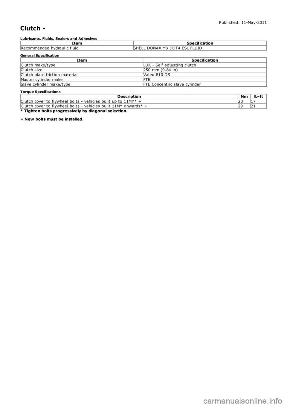
Lubricants, Fluids, Sealers and AdhesivesItemSpecification
Recommended hydraul ic fluidSHELL DONAX Y B DOT4 ESL FLUID
General Specification
ItemSpecification
Clut ch make/t ypeLUK - Self adjus ti ng clutchClut ch s ize250 mm (9.84 in)
Clut ch plat e frict ion mat eri alVal eo 810 DS
Mas ter cylinder makeFTESlave cyli nder make/t ypeFTE Concent ric s lave cylinder
Torque Specifications
DescriptionNmlb-ft
Clut ch cover t o fl ywheel bolt s - vehi cles buil t up to 11MY * +2317Clut ch cover t o fl ywheel bolt s - vehi cles buil t 11MY onwards* +2921
* T ighten bolts progressively by diagonal selection.
+ New bolts must be installed.
Page 1487 of 3229
t he power t rans fer unit .
The crown wheel is support ed in the cas ing on opposi ng t aper rol ler beari ngs whi ch are press ed i nto t he casi ng and t hehous i ng. The drive gear is retained i n t he cas i ng by a housi ng which i s bolt ed to the cas ing and s ealed wi th an O ring seal.The hous i ng is fit t ed wit h a t riple edge oi l seal and fl inger on the out er end of the hous ing which di rect dirt and mois tureaway from the area of the drive gear. Another s eal i s fit ted whi ch prevent s t he ingres s of dirt and mois t ure bet ween thedri ve gear and t he RH hal f shaft .
The pinion gear i s located i n t he hous ing at 90 degrees to the crown wheel drive gear. The pini on gear i s s upport ed i n t hecas i ng on oppos ing taper roll er bearings . The pi nion gear is retai ned in t he housi ng wit h a pre-l oad nut . The outer end oft he pinion gear is spl ined and mat es wit h t he dri ve shaft out put fl ange. The fl ange is s ecured wi th a fl anged bol t which iss crewed int o t he pinion gear.
A coll aps i bl e s pacer is locat ed between the out er t aper roll er beari ng and a s houlder on the pi nion gear. The coll aps ibl es pacer holds t he bearing i n ali gnment and al so col laps es under pres s ure appli ed to the pre-l oad nut . This all ows t hepre-load nut to be t ightened t o a predet ermi ned torque, which coll aps es t he s pacer, s et ti ng the correct bearing pre-loadand t he correct mes hi ng of the pi nion gear and crown wheel drive gear t eet h.
Dri ve from the t rans mis s ion di fferenti al drives t he crown wheel dri ve gear, which in turn rot ates t he pini on gear. Dri ve ispass ed from the pi nion gear to the drive s haft and t he rear different ial via the drive flange att ached to t he pini on gears haft.
Page 2704 of 3229
18. WARNING: Make sure that a new steering column flexible coupling bolt is
installed.
Connect the steering column to the steering gear.
Torque: 25 Nm18.
Connect and s ecure t he cat alys t moni t or s ens or el ect ri cal connect ors . 19.
Install the 2 subframe mounting bolts and remove the jack. 20.
Install the engine undershield.
Refer to: Engine Undershield
(501-02 Front End Body Panel s, Removal and
Installation). 21.
Install the wheels and tires.
Refer to: W heel and Tire
(204-04 W heels and Tires , Removal and Ins t all at i on). 22.
Refill and bleed the power steering.
Refer to: Power Steering System Bleeding
(211-00 St eeri ng Sys t em - General
Informat ion, General Procedures). 23.
Using only four wheel alignment equipment approved by Land Rover, check and adjust
the wheel alignment. 24.
Page 2715 of 3229
1. CAUTION: Make sure that new bolts are installed.
Clean the component mating faces.
With assistance, install the subframe.With assistance, align and secure the differential.Tighten the rear bolts.
Torque: 110 Nm
Tighten the front bolts.
Torque: 175 Nm
1.
2.
CAUTION: Make sure that new bolts are installed.
Align the suspension arms to the subframe and install the bolts, do
not fully tighten at this stage. 2.
Using the special tool, support the subframe. 3.
Connect the transmission breather lines. 4.
5. CAUTIONS:
Make sure that no components catch.
Make sure that new bolts are installed.
With assistance, position the subframe to the body and tighten the
bolts.
Torque: 175 Nm
5.
6.
CAUTION: Make sure that new bolts are installed.
Install the stabilizer clamp bolts, but do not tighten fully at this
stage. 6.
Connect the Active On-demand Coupling module electrical connector. 7.
Re mo ve t he p o we rt ra i n j a ck.
General Equi pment : P o w e rt ra i n Ja ck
8.
9.
CAUTION: Make sure that new bolts are installed.
Install the trailing arm to body brackets.
Torque: 110 Nm9.
10.
CAUTION: Make sure that the brake hose is not twisted
and is correctly located.
Clean the component mating faces.
Install the brake caliper anchor plate.
Torque: 110 Nm
Repeat the above procedure for the other side.
10.
Secure the wheel speed sensor and lead.
11.
Page 2716 of 3229
Torque: 5 NmSecure the lead in the clips.Repeat the above procedure for the other side.
LH side: Connect the ride height sensor electrical connector. 12.
Position and secure the rear shock absorbers.
Install both mass dampers.
Torque: 25 Nm
Repeat the above procedure for the other side.
13.
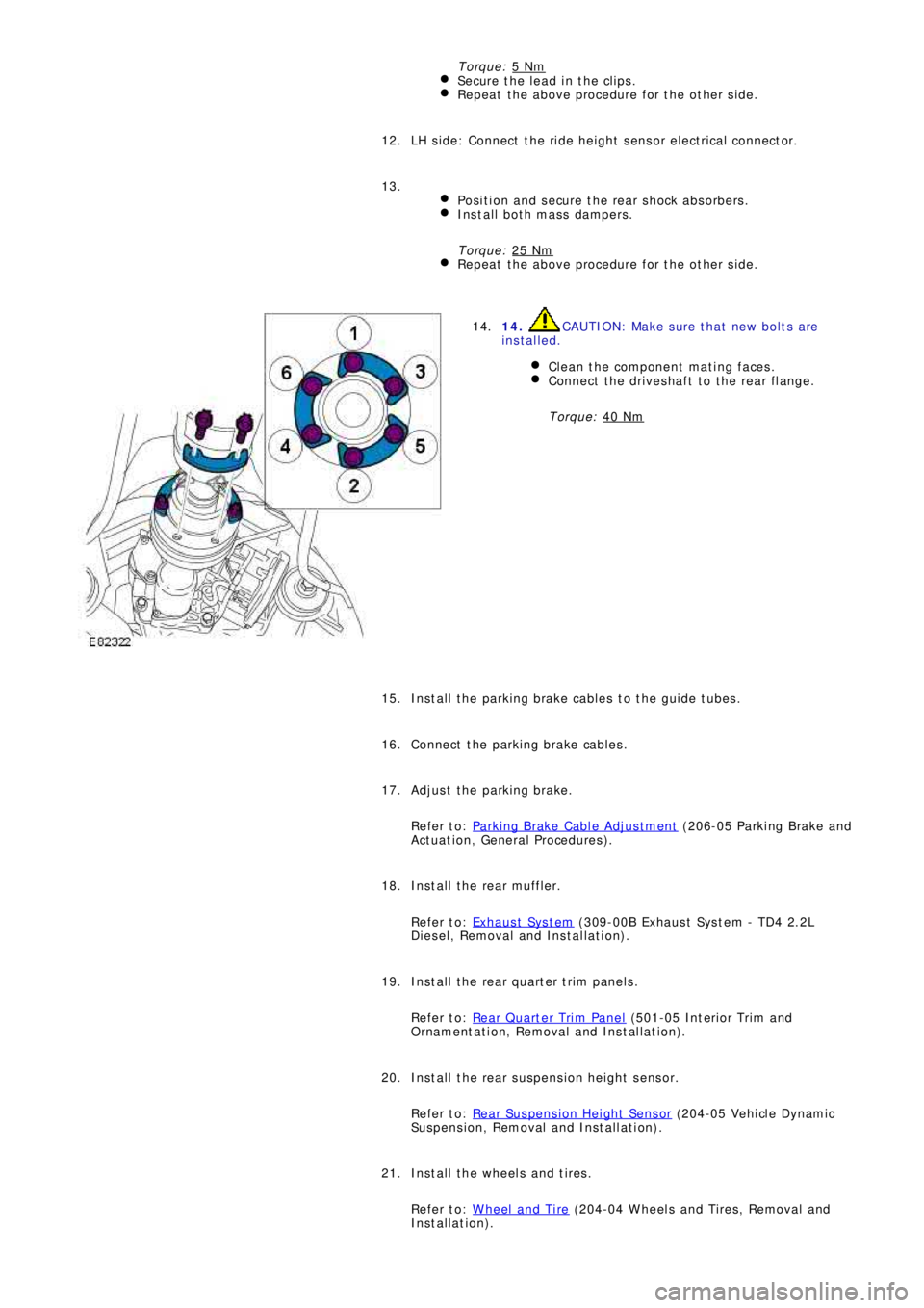
14. CAUTION: Make sure that new bolts are
installed.
Clean the component mating faces.
Connect the driveshaft to the rear flange.
Torque: 40 Nm
14.
Install the parking brake cables to the guide tubes. 15.
Connect the parking brake cables. 16.
Adjust the parking brake.
Refer to: Parking Brake Cable Adjustment
(206-05 Parki ng Brake and
Act uat i on, General Procedures ). 17.
Install the rear muffler.
Refer to: Exhaus t Sys t em
(309-00B Exhaus t Sys t em - TD4 2.2L
Diesel, Removal and Installation). 18.
Install the rear quarter trim panels.
Refer to: Rear Quarter Trim Panel
(501-05 Int eri or Tri m and
Ornament at i on, Removal and Ins t al lat i on). 19.
Install the rear suspension height sensor.
Refer to: Rear Suspension Height Sensor
(204-05 Vehi cl e Dynami c
Suspension, Removal and Installation). 20.
Install the wheels and tires.
Refer to: Wheel and Tire
(204-04 Wheels and Tires, Removal and
Installation). 21.
Page 2717 of 3229
22. CAUTION: Nuts and bolts must be tightened with the
weight of the vehicle on the suspension.
Tighten the stabilizer bar clamp bolts.
Torque: 60 Nm22.
23.
CAUTION: Nuts and bolts must be tightened with the
weight of the vehicle on the suspension.
Tighten the supsension arms to the subframe.
Torque: 175 Nm
During installation, do not tighten the nuts and bolts until
the 4 wheel alignment procedure has been carried out.
23.
Carry out a complete vehicle geometry check and adjustment. 24.