2006 LAND ROVER FRELANDER 2 warning
[x] Cancel search: warningPage 175 of 3229
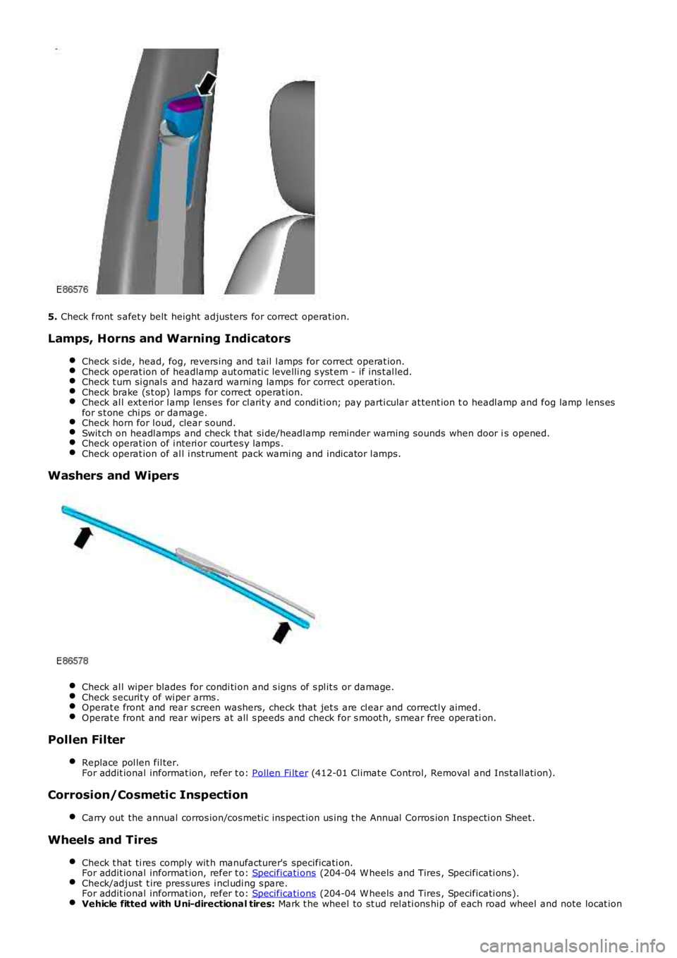
5. Check front s afet y belt height adjus ters for correct operat ion.
Lamps, Horns and Warning Indicators
Check s i de, head, fog, revers ing and tail l amps for correct operat ion.Check operat ion of headlamp aut omati c levelli ng s yst em - if ins t al led.Check t urn si gnal s and hazard warni ng lamps for correct operati on.Check brake (s t op) l amps for correct operat ion.Check al l ext eri or l amp l ens es for cl arit y and condi ti on; pay parti cular at tent ion to headl amp and fog lamp lens esfor s t one chi ps or damage.Check horn for l oud, clear s ound.Swit ch on headl amps and check t hat si de/headl amp reminder warning s ounds when door is opened.Check operat ion of i nteri or courtes y lamps .Check operat ion of al l i nst rument pack warni ng and indicator l amps.
Washers and Wipers
Check al l wiper blades for condi ti on and s igns of s pl it s or damage.Check s ecurit y of wi per arms .Operat e front and rear s creen washers, check that jet s are cl ear and correctl y aimed.Operat e front and rear wipers at all s peeds and check for s moot h, s mear free operation.
Pollen Filter
Replace pol len fil ter.For addit ional informat ion, refer t o: Pollen Fi lt er (412-01 Cl imat e Control, Removal and Ins tall ati on).
Corrosion/Cosmetic Inspection
Carry out the annual corros ion/cos meti c ins pect ion us ing t he Annual Corros ion Inspecti on Sheet .
Wheels and Tires
Check t hat ti res comply wit h manufacturer's specificati on.For addit ional informat ion, refer t o: Specificati ons (204-04 W heels and Tires , Specificati ons ).Check/adjust t ire pres s ures i ncl udi ng s pare.For addit ional informat ion, refer t o: Specificati ons (204-04 W heels and Tires , Specificati ons ).Vehicle fitted with Uni-directional tires: Mark t he wheel to st ud rel ati ons hip of each road wheel and note locat ion
Page 186 of 3229
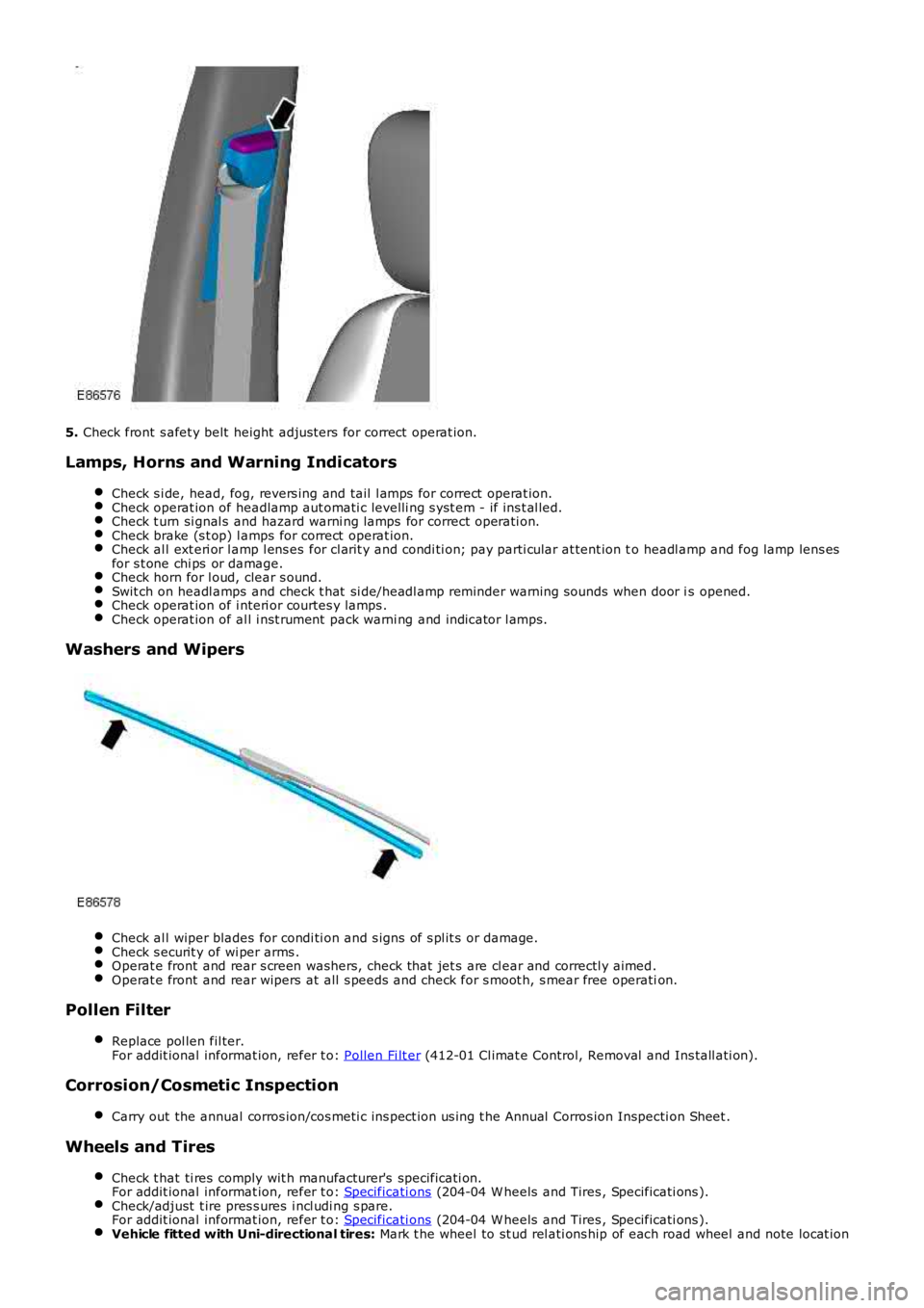
5.
Check front s afet y belt height adjus ters for correct operat ion.
Lamps, Horns and Warning Indicators Check s i de, head, fog, revers ing and tail l amps for correct operat ion. Check operat ion of headlamp aut omati c levelli ng s yst em - if ins t al led.
Check t urn si gnal s and hazard warni ng lamps for correct operati on.
Check brake (s t op) l amps for correct operat ion.
Check al l ext eri or l amp l ens es for cl arit y and condi ti on; pay parti cular at tent ion t
o headl amp and fog lamp lens es
for s t one chi ps or damage. Check horn for l oud, clear s ound.
Swit ch on headl amps and check t hat si de/headl amp reminder warning s ounds when door i
s opened.Check operat ion of i nteri or courtes y lamps .
Check operat ion of al l i nst rument pack warni ng and indicator l amps.
Washers and Wipers
Check al l wiper blades for condi ti on and s igns of s pl it s or damage.
Check s ecurit y of wi per arms .
Operat e front and rear s creen washers, check that jet s are cl ear and correctl y aimed
.Operat e front and rear wipers at all s peeds and check for s moot h, s mear free operati
on.Pollen Filter
Replace pol len fil ter.
For addit ional informat ion, refer t o: Pollen Fi lt er (412-01 Cl imat e Control, Removal and Ins tall ati on).
Corrosion/Cosmetic Inspection
Carry out the annual corros ion/cos meti c ins pect ion us ing t he Annual Corros ion Inspec ti on Sheet .Wheels and Tires
Check t hat ti res comply wit h manufacturer's specificati on.
For addit ional informat ion, refer t o: Specificati ons (204-04 W heels and Tires , Specificati ons ).
Check/adjust t ire pres s ures i ncl udi ng s pare.
For addit ional informat ion, refer t o: Specificati ons (204-04 W heels and Tires , Specificati ons ).
Vehicle fitted with Uni-directional tires:
Mark t he wheel to st ud rel ati ons hip of each road wheel and note locat ion
Page 275 of 3229
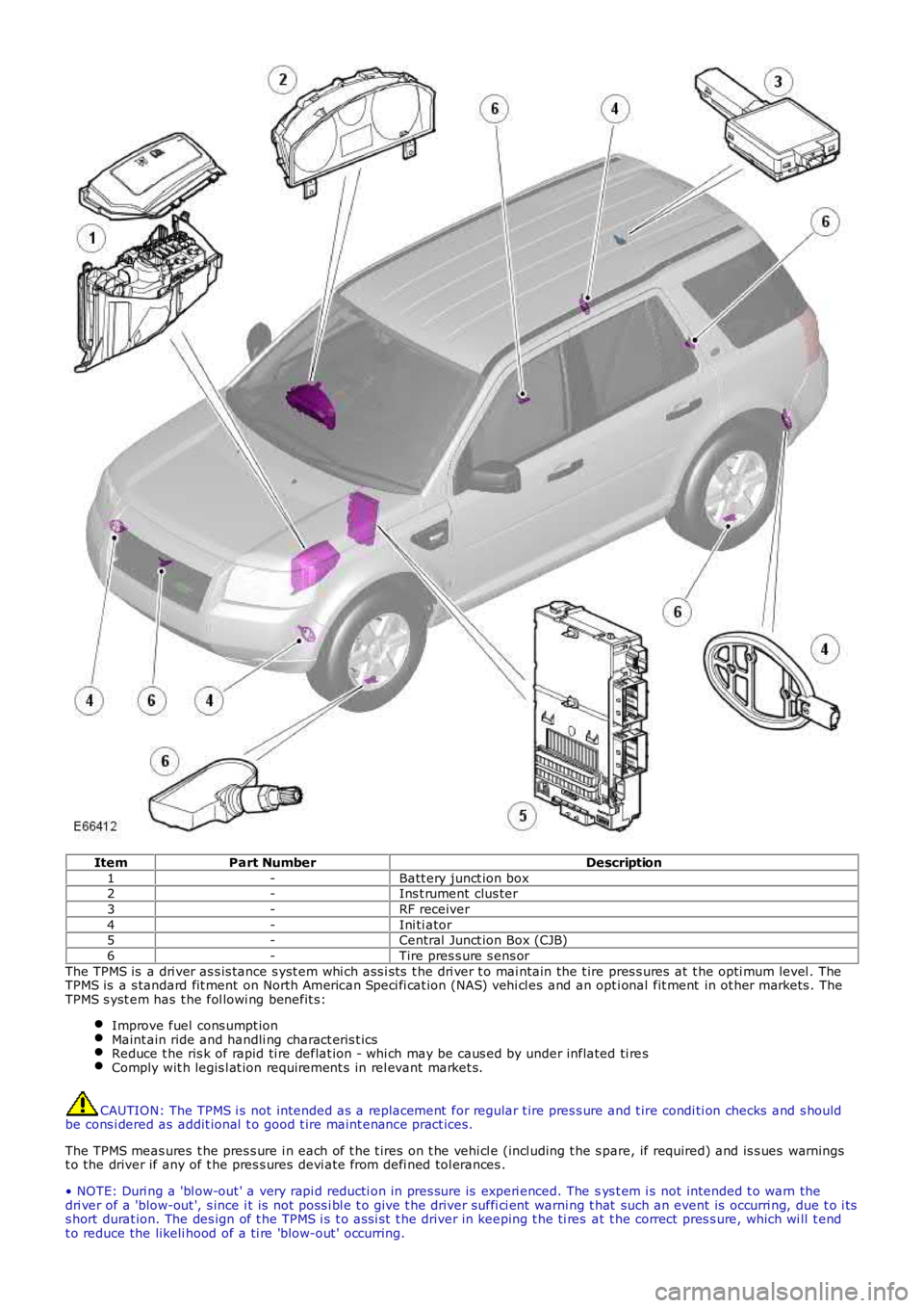
ItemPart NumberDescription
1-Batt ery junct ion box2-Ins t rument clus ter
3-RF receiver
4-Ini ti ator5-Central Junct ion Box (CJB)
6-Tire pres s ure s ens or
The TPMS is a dri ver as s is tance s yst em whi ch ass i st s t he dri ver t o mai ntain the t ire pres s ures at t he opti mum level . TheTPMS is a s tandard fit ment on North American Speci fi cat ion (NAS) vehi cl es and an opti onal fit ment in ot her markets . TheTPMS s yst em has t he fol lowi ng benefit s:
Improve fuel cons umpt ionMaint ain ride and handli ng charact eris t icsReduce t he ris k of rapid ti re deflat ion - whi ch may be caus ed by under inflated ti resComply wit h legis l at ion requirement s in rel evant market s.
CAUTION: The TPMS i s not intended as a replacement for regular t ire pres s ure and t ire condi ti on checks and s houldbe cons i dered as addit ional t o good t ire maint enance pract ices.
The TPMS meas ures t he pres s ure i n each of t he t ires on t he vehi cl e (incl uding t he s pare, if required) and is s ues warningst o the driver if any of t he pres s ures devi ate from defi ned tol erances .
• NOTE: Duri ng a 'bl ow-out ' a very rapi d reducti on in pres sure is experi enced. The sys t em i s not intended t o warn thedri ver of a 'blow-out ', s ince i t is not poss i bl e t o give t he driver suffi ci ent warning t hat such an event is occurri ng, due t o i tss hort durat ion. The des ign of t he TPMS i s t o ass i st t he driver in keeping t he ti res at t he correct pres s ure, which wi ll t endt o reduce the likeli hood of a ti re 'blow-out ' occurring.
Page 276 of 3229
The cont rol ling software for t he TPMS i s located wi thi n t he CJB. The s oft ware det ects t he fol lowing:
t he ti re press ure is bel ow t he recommended low pres sure value - under infl ated t iret he pos i ti on of the t ire on t he vehi cle.
The s ys t em compri s es a Radio Frequency (RF) receiver, 4 init iat ors and 4 ti re press ure s ens ors (5 if t he spare wheel has as ens or fi tt ed).
The 4 i nit iators are hard wi red t o t he CJB. The i nit iators t rans mit 125 KHz Low Frequency (LF) s ignals t o t he t ire pres s ures ens ors which res pond by modifying t he mode s t at us wi thin the RF trans mi s si on. The 315 or 433 MHZ RF s ignals aredetected by the RF recei ver whi ch is l ocat ed at the rear of t he vehicle, behi nd t he headl ining. The RF receiver is connect edt o the CJB on the Local Interconnect Net work (LIN) bus . The received RF s i gnals from t he t ire pres s ure s ensors are pas s edt o the CJB on the LIN bus and contain identi fi cat ion, pres sure, temperat ure and accel erat ion i nformat ion for each wheeland t ire.
The TPMS s oft ware communi cat es wit h t he ins trument cl ust er via t he medium s peed Control ler Area Net work (CAN) bus toprovide t he driver wit h appropri at e warnings. The TPMS s oftware als o i ndi cat es s tat us or fail ure of t he TPMS orcomponents .
Tire Location and Identification
The TPMS can identi fy the pos it ion of t he wheel s on t he vehi cle and as s ign a recei ved ti re press ure s ens or identi fi cat ion t oa s peci fi c posi ti on on t he vehi cl e, for exampl e FL (front l eft ), FR (front ri ght ), RL (rear left ) and RR (rear right). Thi s feat ureis required because of the di fferent pres sure t argets and t hres hold bet ween the front and rear t ires.
The wheel l ocat ion i s performed aut omati cal ly by t he TPMS s oft ware us i ng an 'auto-locati on' funct ion. Thi s functi on is full yautomat ic and requi res no i nput from t he dri ver. The TPMS software automat icall y re-learns t he pos it ion of t he wheel s ont he vehi cl e if t he t ire pres s ure s ensors are replaced or the wheel posi ti ons on t he vehi cl e are changed.
The TPMS s oft ware can aut omat icall y detect, under all operati ng condit ions , the following:
one or more new t ire pres sure s ensors have been fit t edone or more ti re press ure s ens ors have s t opped t rans mi tt ingTPMS s oft ware can reject identi fi cat ions from ti re press ure sens ors whi ch do not belong to the vehiclet he spare wheel and one of t he 'runni ng' wheels on the vehicle have changed pos it ions .
If a new t ire pres s ure s ensor i s fi tt ed on any 'running' wheel , the s oft ware can learn t he new s ens or i dent ificati onautomat ically when the vehicle is driven for more t han 15 mi nut es at a s peed of more than 20 km/h (12.5 mph).
• NOTE: The s pare wheel is not fit ted wit h a t ire pres s ure s ens or.
TPMS Operation
Each ti me t he vehi cl e i s dri ven the TPMS s oft ware act ivates each i ni ti ator i n turn to t rans mit a LF 125 KHz s ignal t o eacht ire pres sure s ensor. The LF si gnal i s received by t he ti re pres sure s ens or which responds by t rans mit ti ng a 315 or 433MHZ (depending on market ) si gnal whi ch is received by t he RF recei ver. The si gnal contains coded data which corres pondst o s ens or identi fi cat ion, air pres s ure, air t emperature and accel erati on data. This i s t hen pas s ed to the CJB on the ISO9141 K Line.
If the vehicle has been parked for more than 15 minutes and t hen dri ven at a s peed of more t han 12.5 mph (20 km/h), t heini ti at ors each fire an LF s ignal in turn for 18 s econds i n t he fol lowing order:
Front LHFront RHRear RHRear LH.
Each ti re press ure s ens or res ponds i n t urn whi ch allows the TPMS s oftware to est ablis h the s ensor pos it ions at t he st art oft he drive cycle. This proces s is repeat ed up t o t hree t imes but l ess if t he s ens or pos i ti ons are already known. The processis known as 'Auto Locati on' and t akes 2 to 4 mi nut es t o compl ete.
Duri ng thi s peri od the t ire pres s ure sens ors t rans mi t at regular int ervals , once every 5 s econds (once every 15 s econds onNAS vehicles ). For the remainder of the drive cycl e t he t ire pres sure s ensors transmit once every 60 s econds or more oft enif a change of ti re pres sure is sens ed unti l the vehicle st ops and the TPMS ret urns t o t he parking mode.
Once the wheel pos it ions have been es t abl is hed, t he i ni ti ators s top t rans mit t ing t he LF s ignal and do not t rans mi t agai nunti l the vehicle has been parked for more than 15 minutes .
The warni ng appears in t he i ns t rument clus ter mes s age cent re when the i nfl at ion press ure has fal len t o 25% of t henominal pres s ure. The dis played mes sage wi ll als o i ncl ude the pos it ion(s) of t he affect ed wheel(s).
The TPMS enters 'Parki ng Mode' aft er the vehicl e s peed has been l es s t han 20 km/h (12.5 mph) for 15 minut es . In parkingmode t he t ire pres sure s ensors transmit a coded RF s ignal once every 13 hours. If t he ti re pres sure decreas es by more
t han 0.06 bar (1 lbf/in2 ), t he s ens or wil l trans mi t more oft en if pres s ure in t he t ire is bei ng los t.
The s pare wheel ti re press ure s ens or als o t rans mit s a si gnal once every 13 hours i n t he s ame manner as the 'running
wheels ' when in parki ng mode. If t he t ire pres sure decreases by more t han 0.06 bar (1 l bf/i n2 ), the s ensor wi ll t rans mitmore oft en if press ure in t he t ire is bei ng los t .
Initiators
Page 278 of 3229

The care point s detai led i n 'Tire Changing' earlier i n t hi s s ect ion must be foll owed to avoi d damage to the sens or. If a news ens or is fi tt ed, a new nut, s eal and was her mus t als o be fit ted and the s ensor nut t ightened t o t he correct torque asgiven i n the Service Repai r Manual .
Instrument Cluster Indications
ItemPart NumberDescription
1-Low ti re press ure warning indicator
2-Mes s age cent reThe warni ng indicati ons to the driver are common on all vehi cl es fi tt ed wi th TPMS. The dri ver i s alerted t o s ys tem warningsby a l ow t ire pres s ure warning i ndi cat or in t he i ns t rument clus ter and an appli cable text mes s age in t he mes s age cent re.
The TPMS s oft ware wit hi n t he CJB pas s es s yst em s t atus i nformat ion to the i nst rument clus ter on t he medi um s peed CANbus. The i nst rument clus t er t hen convert s t his dat a int o il lumi nat ion of t he warni ng indi cat or and di spl ay of an appropriat emes s age.
W hen t he i gni ti on is s wi tched on, the warning i ndi cat or is i ll uminated for 3 s econds for a bul b check.
• NOTE: If the vehicle is not fit ted wi th the TPMS, t he warning indicator wi ll not ill uminat e.
The ins t rument clus ter checks, wit hi n t he 3 s econd bul b check peri od, for a CAN bus mes s age from t he TPMS. Duri ng thi st ime the TPMS performs int ernal tes ts and CAN bus ini ti al is ati on. The warning i ndi cat or wil l be ext inguis hed if t he TPMSs oft ware does not is s ue a faul t mes s age or t ire pres s ure warning mes s age.
If a TPMS faul t warning mess age is det ect ed by t he ins t rument clus ter at ignit ion on, t he warni ng indicator wi ll flas h for 75s econds aft er the 3 s econd bulb check period and t hen remai n permanent ly i lluminated.
If a ti re pres sure warni ng mes sage i s detected by the i nst rument clus t er at i gni ti on on, the warning i ndi cat or wil lexti nguis h briefly after t he 3 s econd bulb check peri od, before re-il lumi nat ing to indicate a ti re pres sure warni ng.
The fol lowing table shows t he warni ng indicat or funct ionali ty for given event s:
EventInstrument Cluster IndicationsLow pres s ure warning l imit reached in hi ghs peed modeW arni ng indicat or i ll uminated. 'TY RE PRESSURES LO W FOR SPEED' mes sagedis played.Low pres s ure warning l imit reached in onewheel in l ow s peed modeW arni ng indicat or i ll uminated. 'CHECK ALL TY RE PRESSURES XX LOW 'mes sage di spl ayed.
Low pres s ure warning l imit reached in moret han one wheel i n low s peed modeW arni ng indicat or i ll uminated. 'CHECK ALL TY RE PRESSURES' mes s agedis played.
W arning l imi t reached in any 'running' wheeland no l ocat ion s peci fi ed by TPMSW arni ng indicat or i ll uminated. 'CHECK ALL TY RE PRESSURES' mes s agedis played.
W arning l imi t reached in s pare wheel (if fit ted)W arni ng indicat or i ll uminated for 20 s econds and again at s ubsequentignit ion cycles . 'CHECK SPARE TY RE PRESSURE' mess age dis played.
TPMS faul tW arni ng indicat or flas hing for 75 s econds and then remains permanent lyil lumi nat ed. 'TY RE PRESSURE MONITORING SY STEM FAULT' mes sagedis played.
Page 279 of 3229

EventInstrument Cluster Indications
No t rans mi ss i on from a specific t ire pres s ures ensor or Speci fic tyre pres sure s ensor faul tW arni ng indicat or flas hing for 75 s econds and then remains permanent lyil lumi nat ed. 'XX TY RE PRESSURE NOT MONITORED' mes s age dis played for20 s econds.
No t rans mi ss i on from more t han one tyrepres s ure s ens or or More t han one tyrepres s ure s ens or fault
Amber warning i ndicat or fl ashi ng for 75 s econds and t hen remai nspermanentl y il lumi nat ed. 'TY RE PRESSURE MONITORING SY STEM FAULT'mes sage di spl ayed for 20 s econds.CAN s i gnal s mis s ingW arni ng indicat or flas hing for 75 s econds and then remains permanent lyil lumi nat ed. 'TY RE PRESSURE MONITORING SY STEM FAULT' mes sage i sdis played for 20 s econds .
• NOTE: 'XX' is the t ire pos it ion on t he vehicle, for example Front Left, Front Ri ght , Rear Left or Rear Right .
CONTROL DIAGRAM
• NOTE: A = Hardwi red; F = RF t ransmis s ion; J = ISO 9141 K Line; N = CAN bus Medium s peed; W = LF t rans mi ss i on
Page 296 of 3229
programs.
Incorrect Program Usage
Selecti on of an inappropri at e program i s dis couraged in t he followi ng ways:
The act ive program icon is conti nual ly di spl ayed i n t he ins t rument clus ter mes s age centerThe Terrai n Res pons e control modul e 'l ocks ' out cert ain funct ions i n s ome programs, for exampl e:- cruis e control is only avai lable wi th the special programs off or gras s/gravel/s now program- t rans mis s ion 'Sport' mode i s deact ivated i n all s peci al programs .W hen t he i gni ti on has been in t he off mode, cont inuall y for more t han 6 hours , t he Terrai n Respons e s yst emdefault s t o t he special programs off.
Selecti on of an inappropri at e program for the t errain condit ions wil l not endanger the dri ver or cause damage to thevehi cl e. Cont inued us e of an inappropri ate program may reduce t he li fe of s ome component s . The driver may not icereduced vehi cl e res ponse, wi th the engine and t rans mi ss i on bei ng les s respons ive t han in s peci al programs off. Al so, i ns ome programs, HDC wil l remai n on, si gni fi ed by il lumi nat ion of t he HDC indicator in the i nst rument clus t er. The dri ver mayals o not ice t orque 'wi nd-up' i n t he act ive on-demand coupli ng caus ing a braking effect when the vehicl e is manoeuvred i ns ome s peci al programs .
Driver Information
The high-l ine i nst rument clus t er fit t ed to al l vehi cl es wit h Terrain Res pons e, cont ains a mess age center which di spl aysvehi cl e i nformat ion to t he driver. The mes s age cent er contai ns the Terrain Res ponse program icons which dis play t hecurrent ly s elected program. If no s ymbol i s dis played, no special program is sel ect ed and the sys tem is in 'Specialprograms off'.
Any required changes t o t he s ub-s ys t ems are al s o pass ed t o t he dri ver i n t he form of i ndi cat or ill uminat ion i n t heins t rument clus ter or appropriat e mes s ages i n t he mes s age center, 'HDC OFF' for example.
In certai n operati ng condi ti ons , t he Terrai n Res pons e s yst em al s o dis plays advi ce or warning mess ages to ens ure thedri ver i s us ing t he vehi cl e t o it s full potenti al, for example, s t eering angle is dis played i n t he mes sage center t o avoi ddri vi ng in deep rut s wit h s t eering l ock appli ed.
DIAGNOSTICS
The Terrai n Res pons e control modul e s tores informati on on detect ed Terrai n Respons e faul ts and CAN errors whi ch can beint errogat ed usi ng IDS. The Terrain Res ponse s ub-s ys t ems and t he ins trument cl ust er als o s tore informat ion relat ing t oCAN errors from t he Terrain Res pons e control modul e.
The cont rol module al s o s tores the mil es travel ed and ti me el aps ed for t he i ndi vi dual programs which can al so be ret ri evedus ing IDS. Thi s informat ion aids di agnos is of t he Terrain Res pons e s ys tem and als o provi des an indicati on of Terrai nRespons e s yst em abus e by t he dri ver whi ch can l ead to premat ure component failure.
This i nformat ion can al so be us ed to check cus t omer concerns , for exampl e, hi gh fuel cons umpt ion whi ch may be due t ocont inued us e of a cert ain program.
Terrain Response System Fault Diag nosis
Terrai n Res pons e relies on the correct funct ionali ty of t he 4 s ub-s ys tems . If one of the s ub-s ys tems develops a fault , theTerrai n Res pons e s ys tem wil l not funct ion, even though the fault i s NOT in t he Terrain Res pons e s ys tem.
T he T errain Response control module and rotary control should only be investigated if there are no apparent faultsin any of the sub-systems. If a fault in a sub-system is subsequently corrected, the T errain Response system willfunction normally after an ignition mode 1 and 2 (on and off) cycle.
Terrain Response Sub-System Faults
W hen a fault occurs i n a s ub-s yst em, t he dri ver i s alert ed by t he il lumi nat ion of a warning indicator and/or an appropri atemes s age for that s ub-s yst em in t he i ns t rument clus ter mes s age cent er. There wi ll be no warning of a Terrain Res ponses ys t em fault .
W hen a sub-sys t em faul t is present and t he dri ver at tempt s t o s el ect a different Terrain Res pons e program us i ng therot ary control or at t he next ignit ion mode 2 (on) cycl e, a mes sage 'SY STEM FAULT SPECIAL PROGRAMS NOT AVAILABLE'wil l appear in the mess age cent er. This impl ies t hat t he Terrain Res pons e s ys tem has a faul t, but only because asub-system fault is preventing its operation. Thi s mes sage will be di spl ayed for 5 s econds per ignit ion mode 2 cycl e, butis repeat ed i f a further s electi on is made by the driver usi ng t he Terrai n Respons e rot ary control or at t he next ignit ionmode 2 (on) cycle.
• NOTE: The mes s age 'SY STEM FAULT SPECIAL PRO GRAMS NOT AVAILABLE' can al so be generated by a fault i n t he Terrai nRespons e rot ary control or control modul e. Refer to the foll owing i nformat ion for det ail s of rot ary control or control modul efaul ts .
It is not possible for the T errain R esponse control module to cause any fault behavior (w arning indicator illuminationor message generation) in any of the 4 sub-systems. Illuminati on of a s ub-s ys t em warning i ndi cat or and/or as ub-s ys t em relat ed mes sage wi ll NEVER be ass ociated wit h a Terrain Res ponse cont rol module or Terrain Res pons es ys t em fault .
The s ub-s ys t em control modul es can det ect a fault wit h the CAN s ignal from t he Terrai n Res pons e control modul e. If afaul t in t he Terrain Res pons e s ys tem is det ect ed, the s ub-s ys tem cont rol modules wi ll operate in t he 'Special programs off's ett ing. The s ub-s ys t em control modul es wil l record a fault code for a fail ure of t he Terrai n Res pons e CAN si gnal . Thes efaul ts can be retrieved us ing IDS and wi ll provide us eful informat ion t o i ndi cat e i nves ti gat ion of t he Terrain Res pons econt rol module or t he CAN net work.
Terrain Response Rotary Control or Control Module Fault
Page 416 of 3229
brake boos ter.
5. Operate the engine for a minimum of 10 s econds at a fast i dle. Stop the engine and al low t he vehicle t o s t andfor 10 mi nut es. Then, appl y the brake pedal wi th approxi mately 89 N (20lb) of force. The pedal feel (brakeappli cat ion) s houl d be t he s ame as t hat not ed wit h t he engine runni ng. If the brake pedal feel s hard (no poweras s is t), ins t al l a new valve and t hen repeat t he tes t. If t he brake pedal s t ill feels hard, i ns t all a new brakeboos ter. If t he brake pedal movement feel s s pongy, bleed t he brake s ys t em.REFER t o: Brake Syst em Bl eedi ng (206-00 Brake Syst em - General Informati on, General Procedures ) /Brake Sys t em Pres s ure Bl eedi ng (206-00 Brake Syst em - General Informati on, General Procedures ).
5.
Brake Master Cylinder
Us ual ly, t he fi rs t and s tronges t indicat or of anything wrong i n t he brake s ys t em i s a feeling through t he brake pedal. Indiagnosi ng the condit ion of t he brake mas t er cyli nder, check pedal feel as evidence of a brake concern. Check for brakewarni ng lamp ill uminat ion and t he brake fluid level i n t he brake mas t er cyli nder reservoi r.
Normal Condit ions
The fol lowing condit ions are cons idered normal and are not i ndi cat ions t hat t he brake mast er cyl inder i s i n need of repair.
Modern brake sys tems are des igned t o produce a pedal effort that is not as hard as in the pas t . Compl aint s of lightpedal effort s s houl d be compared t o t he pedal efforts of another vehi cl e of t he s ame model and year.The fl uid l evel wi ll fal l wit h brake pad wear.
Abnormal Condi ti ons
Changes i n t he brake pedal feel or brake pedal travel are indicators t hat s omet hi ng coul d be wrong in the brake sys tem.The diagnost ic procedure and techni ques us e brake pedal feel , warning i ndi cat or il lumi nat ion and l ow brake flui d level asindicat ors t o diagnosi ng brake s yst em concerns . The foll owing condi ti ons are consi dered abnormal and indi cat e t hat t hebrake mas t er cyli nder i s in need of repai r:
• NOTE: Pri or to carrying out any diagnosi s , ens ure the brake sys tem warni ng indicator i s functi onal .
Brake pedal goes down fast . This could be caus ed by an external or int ernal leak.Brake pedal goes down s l owl y. Thi s coul d be caused by an int ernal or external l eak.Brake pedal is l ow or feels spongy. Thi s condit ion may be caus ed by no fl ui d i n the brake mas ter cylinder, reservoi rcap vent holes cl ogged or air i n t he hydraul ic s ys tem.Brake pedal effort is excess ive. This may be caus ed by a bi nd or obs t ructi on in the pedal/li nkage, a faul tynon-ret urn val ve, boost er or ins ufficient boos t er vacuum.Rear brakes lock up during light pedal force. Thi s may be caus ed by damaged brake pads , a parti ally appl ied parkingbrake, a damaged ABS s ens or or bearing fail ure.Brake pedal effort errat ic. This condit ion could be caus ed by the brake boos t er or incorrectl y ins tal led brake pads .Brake warning i ndi cat or is on. This may be caus ed by low fl uid l evel or fl oat as s embly damaged.
Non Pressure Leaks
Any reduced fl uid volume in t he brake mast er cyl inder res ervoi r may be caused by two types of none pres sure externalleaks .
Type 1: An ext ernal leak may occur at the brake mast er cyl inder res ervoir cap because of incorrect posi ti oning of t hegasket and cap. Repos it ion cap and gasket .
Type 2: An ext ernal leak may occur at the brake mast er cyl inder res ervoir mounti ng seal s. Repair s uch a l eak by ins tall ingnew s eals and make s ure that t he brake mas t er cyli nder reservoi r ret ai ning bolt i s correct ly i nst all ed.