2006 LAND ROVER FRELANDER 2 warning
[x] Cancel search: warningPage 1221 of 3229
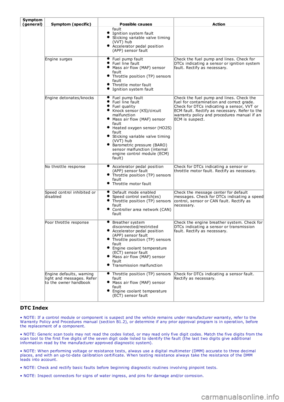
Symptom(general)Symptom (specific)Possible causesAction
faultIgnit ion s ys tem faultSt icking vari able valve t iming(VVT) hubAccelerat or pedal posi ti on(APP) s ens or fault
Engine s urgesFuel pump faul tFuel li ne faultMas s ai r fl ow (MAF) s ens orfaultThrott le pos it ion (TP) s ens orsfaultThrott le motor faul tIgnit ion s ys tem fault
Check t he fuel pump and l ines. Check forDTCs indicati ng a s ens or or ignit ion sys temfault . Rect ify as neces s ary.
Engine detonates /knocksFuel pump faul tFuel li ne faultFuel qual it yKnock s ens or (KS)/ci rcuitmalfuncti onMas s ai r fl ow (MAF) s ens orfaultHeat ed oxygen s ensor (HO2S)faultSt icking vari able valve t iming(VVT) hubBarometric press ure (BARO)sens or malfuncti on (internalengine cont rol module (ECM)fault )
Check t he fuel pump and l ines. Check thefuel for cont aminat ion and correct grade.Check for DTCs i ndi cat ing a s ens or, VVT orECM fault . Rect ify as neces s ary. Refer t o t hewarrant y policy and procedures manual if anECM is sus pect .
No t hrot tl e res ponseAccelerat or pedal posi ti on(APP) s ens or faultThrott le pos it ion (TP) s ens orsfaultThrott le motor faul t
Check for DTCs i ndi cat ing a s ens or orthrot tl e mot or fault . Rect ify as neces s ary.
Speed cont rol inhibi ted ordis abledDefault mode enabledSpeed control s wi tch(es )Thrott le pos it ion (TP) s ens orsfaultCont roll er area network (CAN)fault
Check t he mes sage center for defaul tmess ages. Check for DTCs i ndi cat ing a speedcontrol, s ensor or CAN fault . Rect ify asnecess ary.
Poor throt tl e respons eBreather s ys t emdi s connect ed/res t ri ct edAccelerat or pedal posi ti on(APP) s ens or faultThrott le pos it ion (TP) s ens orsfaultEngine coolant t emperature(ECT) s ens or faultMas s ai r fl ow (MAF) s ens orfaultTransmis si on mal funct ion
Check t he engi ne breather s yst em. Check forDTCs indicati ng a s ens or or transmis s ionfault . Rect ify as neces s ary.
Engine default s , warningli ght and mess ages. Refert o t he owner handbook
Thrott le pos it ion (TP) s ens orsfaultMas s ai r fl ow (MAF) s ens orfaultEngine coolant t emperature(ECT) s ens or fault
Check for DTCs i ndi cat ing a s ens or fault .Rect ify as neces sary.
DTC Index
• NOTE: If a cont rol module or component i s s uspect and the vehicl e remai ns under manufacturer warrant y, refer t o t heW arranty Pol icy and Procedures manual (s ect ion B1.2), or determine i f any pri or approval program is i n operat ion, beforet he replacement of a component.
• NOTE: Generic scan t ool s may not read the codes li st ed, or may read only fi ve digit codes . Mat ch the five di git s from t hes can tool to the firs t fi ve di git s of the seven digi t code l is ted to ident ify t he faul t (t he las t t wo digi ts gi ve addi ti onalinformat ion read by the manufact urer approved diagnos t ic s ys tem).
• NOTE: W hen performing volt age or res is t ance t est s , always use a digi tal mult imeter (DMM) accurat e t o t hree deci malplaces, and wi th an up-t o-date cal ibrat ion cert ificate. W hen tes ti ng res is t ance al ways take t he res is t ance of t he DMMleads i nt o account .
• NOTE: Check and recti fy bas ic faul ts before beginni ng diagnos t ic rout ines i nvol vi ng pinpoint t es t s.
• NOTE: Ins pect connect ors for s igns of water ingres s , and pins for damage and/or corros ion.
Page 1247 of 3229
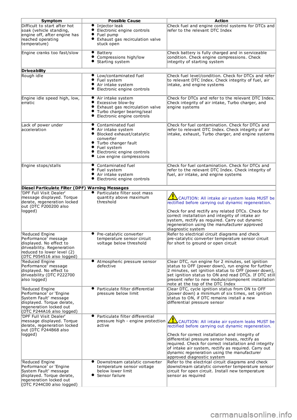
SymptomPossible CauseAction
Di fficul t t o s tart aft er hots oak (vehicle st andi ng,engine off, aft er engi ne hasreached operati ngt emperature)
Injector leakElectronic engine controlsFuel pumpExhaus t gas recircul ati on val ves tuck open
Check fuel and engine control sys tems for DTCs andrefer t o t he rel evant DTC Index
Engine cranks t oo fas t/s lowBatt eryCompres s ions high/lowSt arti ng s yst em
Check batt ery is fully charged and in s ervi ceablecondit ion. Check engine compres s ions . Checkint egrit y of s tart ing sys tem
Driveability
Rough idl eLow/contami nat ed fuelFuel s ys temAir i ntake s yst emElectronic engine controls
Check fuel l evel /condi ti on. Check for DTCs and referto relevant DTC Index. Check i ntegri ty of fuel, airint ake, and engi ne s yst ems
Engine i dl e s peed high, low,errati cAir i ntake s yst emExces s ive blow-byExhaus t gas recircul ati on val veTurbo charger bearing/sealElectronic engine controls
Check for DTCs and refer t o t he rel evant DTC Index.Check i nt egri ty of ai r intake, Turbo charger, andengi ne s ys t ems
Lack of power underaccel erati onContami nat ed fuelAir i ntake s yst emBlocked exhaus t/cat alyt icconverterTurbo changer faul tFuel s ys temElectronic engine controlsLow engine compres s ions
Check for fuel cont aminati on. Check for DTCs andrefer t o relevant DTC Index. Check int egrit y of airint ake, exhaus t, Turbo charger, and engi ne s ys t ems
Engine s t ops /st all sContami nat ed fuelFuel s ys temAir i ntake s yst emElectronic engine controls
Check for fuel cont aminati on. Check for DTCs andrefer t o t he rel evant DTC Index. Check int egrit y offuel, ai r intake, and engi ne s ys t ems
Diesel Particulate Filter (DPF) Warning Messages
'DPF Ful l Vi s it Dealer'mes s age dis played. Torquederat e, regenerati on lockedout (DTC P200200 als ol ogged)
Part iculat e fi lt er soot mas squant it y above maximumt hres hol dCAUTION: All i nt ake air s yst em leaks MUST berecti fi ed before carrying out dynamic regenerat ion.
Check for and recti fy any related DTCs . Check forcorrect ins tal lati on and int egrit y of i nt ake airsys t em, recti fy as requi red. Carry out dynami cregenerati on usi ng t he manufacturer approveddiagnos t ic s yst em
'Reduced Engi nePerformance' mes s agedis played. No effect t odri veabi lit y. Regenerat ionreduced t o lower level (2)(DTC P054516 al so logged)
Pre-cat alyt ic convertert emperature s ens or circui tvolt age bel ow t hres hol d
Refer to elect rical circui t diagrams and checkpre-cat al yti c convert er temperat ure s ens or ci rcuitfor s hort t o ground or open ci rcuit
'Reduced Engi nePerformance' mes s agedis played. No effect t odri veabi lit y (DTC P222700als o l ogged)
At mospheri c pres s ure s ens ordefecti veClear DTC, run engine for 2 mi nut es, s et igni ti onst atus to O FF (power down), run engine for further2 mi nut es , set i gni ti on s tat us to OFF (power down),set i gni ti on s tat us to ON and read DTCs. If DTC s t illpres ent refer t o new module/component ins tal lati onnot e at t he t op of the DTC Index
'Reduced Engi nePerformance' or 'EngineSyst em Fault ' mes sagedis played. Torque derate,regenerat ion l ocked out(DTC P244A16 al so logged)
Part iculat e fi lt er different ialpres s ure bel ow li mitClear DTC, cycle i gni ti on s tat us from ON t o OFF(power down) a mi ni mum of s i x ti mes , set i gni ti onst atus to O N, if DTC remains i ns t all a newdifferent ial pres sure s ens or
'DPF Ful l Vi s it Dealer'mes s age dis played. Torquederat e, regenerati on lockedout (DTC P244B68 als ol ogged)
Part iculat e fi lt er different ialpres s ure hi gh - engi ne prot ect ionacti veCAUTION: All i nt ake air s yst em leaks MUST berecti fi ed before carrying out dynamic regenerat ion.
Check for correct ins tall ati on and int egrit y ofdifferent ial pres sure s ens or hoses , rect ify asrequired. Check for correct i ns t allat ion and i ntegri tyof intake ai r sys tem, rect ify as requi red. Carry outdynami c regenerati on us ing t he manufacturerapproved di agnos ti c s ys t em'Reduced Engi nePerformance' or 'EngineSyst em Fault ' mes sagedis played. Torque derate,regenerat ion l ocked out(DTC P244C00 al so logged)
Downs tream catalyt ic convertert emperature s ens or volt agebelow lower li mitSensor failure
Refer to the el ect ri cal circui t diagrams and checkdowns t ream cat al yti c convert er temperat ure sens orci rcuit for open ci rcuit . Ins tal l new temperat uresens or as required
Page 1585 of 3229
The fuel deli very module flange i s s eal ed to the t ank wit h an O-ring and s ecured wi th a locki ng ring.
The lower part of t he fuel deli very module forms the fuel del ivery pot , and provides the locat ion for the in-t ank pump andt he 2 jet pumps . The delivery pot provi des a cons t ant res ervoir of fuel for t he engine drawn fuel supply. The engine fuels uppl y and ret urn l ines are immers ed in the del ivery pot .
The delivery pot is mai ntained full by t he 2 jet pumps . The i n-t ank pump draws fuel from wit hin the fuel deli very pot andforces the fuel t hrough t he 2 jet pumps . The flow of fuel t hrough each jet pump creat es a venturi effect t hat draws fuelfrom bot h s ides of t he fuel tank i nto the fuel deli very pot. Surpl us fuel entering the fuel deli very pot overflows into theus abl e s ide of t he fuel t ank.
A valve i s l ocated in t he l ower (usabl e tank s i de) jet pump s uppl y ori fi ce. The valve i s open when the i n-t ank pump isenergized and t he lower jet pump is s upplying fuel i nto the fuel del ivery pot . The val ve wil l cl os e when the i n-t ank pump isde-energized t o prevent fuel drai ni ng from the fuel del ivery pot .
The in-tank pump is energized by t he fuel pump relay l ocat ed in the Cent ral Juncti on Box (CJB). The Engine Cont rol Module(ECM) energi zes the fuel pump relay at al l ti mes when t he ignit ion i s in power modes 4 (Acces s ory) t o 9 (Engi ne crank).For addit ional informat ion, refer t o: Electroni c Engi ne Controls - 2.2L Dies el (303-14 El ect ronic Engine Cont rols - 2.2LDies el, Des cript ion and Operat ion).
A modi fi ed fuel delivery modul e i s ins tal led for col d climat e market vehicl es that feat ure a fuel fi red boos ter heater andauxi li ary fuel pump. The modified fuel del ivery modul e incorporat es a s eparate fuel supply line that connects t o anauxi li ary fuel pump, mounted on the ext erior RH si de of the tank. An addi ti onal fuel l ine connects the auxil iary fuel pumpt o the fuel fi red boos ter heat er.For addit ional informat ion, refer t o: Fuel Fired Boost er Heat er (412-02B Auxi liary Cli mate Cont rol , Des cri pti on andOperat ion).
Fuel Sender Units
The 2 MAPPS fuel s ender uni ts are located on eit her s ide of t he s addl e s haped tank, and connect t o t he int ernal elect ricalconnecti ons on the fuel del ivery modul e fl ange. Each s ens or provides an elect rical signal t o t he CJB t hat i s proport ionatet o the fuel level i n each s ide of t he tank.
The act ual fuel level i n t he t ank i s calculated by the CJB and t rans mit t ed via t he medium s peed Cont roll er Area Net work(CAN) bus t o t he ins t rument clus ter.
A warning l amp is incorporat ed in t he i ns t rument clus ter and wi ll il lumi nat e when t he fuel l evel is at, or below apredetermined l evel . On vehi cles wi th a high-l ine i nst rument clus ter, a mes s age is di spl ayed and a chi me i s s ounded t oinform the driver to refuel .
For addit ional informat ion, refer t o:
Ins trument Clus ter (413-01 Ins t rument Clus t er, Descripti on and Operat ion),Informat ion and Mes s age Cent er (413-08 Informati on and Mes sage Cent er, Descripti on and Operat ion).
Fuel Tank Breather Valve
The breat her valve i s located i n t he fuel t ank and is connected to the fuel deli very module fl ange vi a an i nt ernal breatherhose. The breat her valve al lows ai r to es cape and ent er the fuel tank t o compens at e for t he changing vol ume wit hin thet ank.
FUEL TANK FILLER
Page 1593 of 3229
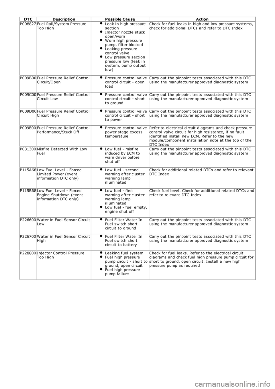
DT C
Description Possible Cause Action
P008827 Fuel Rai l/Sys t em Pres s ure -
Too Hi gh Leak i n high pres s ure
s ecti on Injector nozzl e s t uck
open/worn W orn hi gh pres s ure
pump, fil ter blocked Leaking pres s ure
control val ve Low pres sure s ect ion
press ure low (l eak in
s ys tem, pump out put
l ow) Check for fuel leaks in hi gh and low pres sure s yst ems ,
check for addit ional DTCs and refer t o DTC Index
P009B00 Fuel Pres sure Reli ef Cont rol
Ci rcuit /Open Press ure cont rol valve
control ci rcuit - open
l oad Carry out the pi npoint t es ts as s oci at ed wi th this DTC
usi ng t he manufact urer approved diagnost ic s ys tem
P009C00 Fuel Pres sure Reli ef Cont rol
Ci rcuit Low Press ure cont rol valve
control ci rcuit - s hort
t o ground Carry out the pi npoint t es ts as s oci at ed wi th this DTC
usi ng t he manufact urer approved diagnost ic s ys tem
P009D00 Fuel Pres sure Reli ef Cont rol
Ci rcuit Hi gh Press ure cont rol valve
control ci rcuit - s hort
t o power Carry out the pi npoint t es ts as s oci at ed wi th this DTC
usi ng t he manufact urer approved diagnost ic s ys tem
P009E00 Fuel Pres sure Reli ef Cont rol
Performance/St uck O ff Press ure cont rol valve
power s tage exces s
t emperat ure Refer to electrical ci rcuit diagrams and check pres s ure
cont rol valve circui t for high resi s tance, i f no faul t
identi fi ed ins tal l new ECM. Refer to the new
module/component i nst all at ion not e at t he top of t he
DTC Index
P031300 Mi s fire Det ect ed W i th Low
Fuel Low fuel - mis fire
i nduced by ECM to
warn driver before
s hut off Carry out the pi npoint t es ts as s oci at ed wi th this DTC
usi ng t he manufact urer approved diagnost ic s ys tem
P115A68 Low Fuel Level - Forced
Limit ed Power (event
i nformat ion DTC only) Low fuel - s econd
warning after clus ter
warning l amp
i ll uminated Check for addi ti onal rel ated DTCs and refer t o rel evant
DTC Index
P115B68 Low Fuel Level - Forced
Engine Shutdown (event
i nformat ion DTC only) Low fuel - fi rs t
warning after clus ter
warning l amp
i ll uminated Low fuel - fuel empty,
engine shut off Check fuel l evel . Check for addit ional rel at ed DTCs and
refer t o relevant DTC Index
P226600 W ater in Fuel Sensor Circui t
Low Fuel Filt er W at er In
Fuel s wit ch short
ci rcuit t o ground Carry out the pi npoint t es ts as s oci at ed wi th this DTC
usi ng t he manufact urer approved diagnost ic s ys tem
P226700 W ater in Fuel Sensor Circui t
Hi gh Fuel Filt er W at er In
Fuel s wit ch short
ci rcuit t o batt ery Carry out the pi npoint t es ts as s oci at ed wi th this DTC
usi ng t he manufact urer approved diagnost ic s ys tem
P228800 Injector Control Press ure
Too Hi gh Leaking fuel s ys tem Fuel high pres s ure
pump ci rcuit - s hort t o
ground, open circuit Fuel high pres s ure
pump fail ure Check for fuel leaks. Refer t o t he electrical ci rcuit
diagrams and check fuel high pres s ure pump circuit for
s hort to ground, open circui t. Inst all a new high
pres sure pump as requi red
Page 1767 of 3229
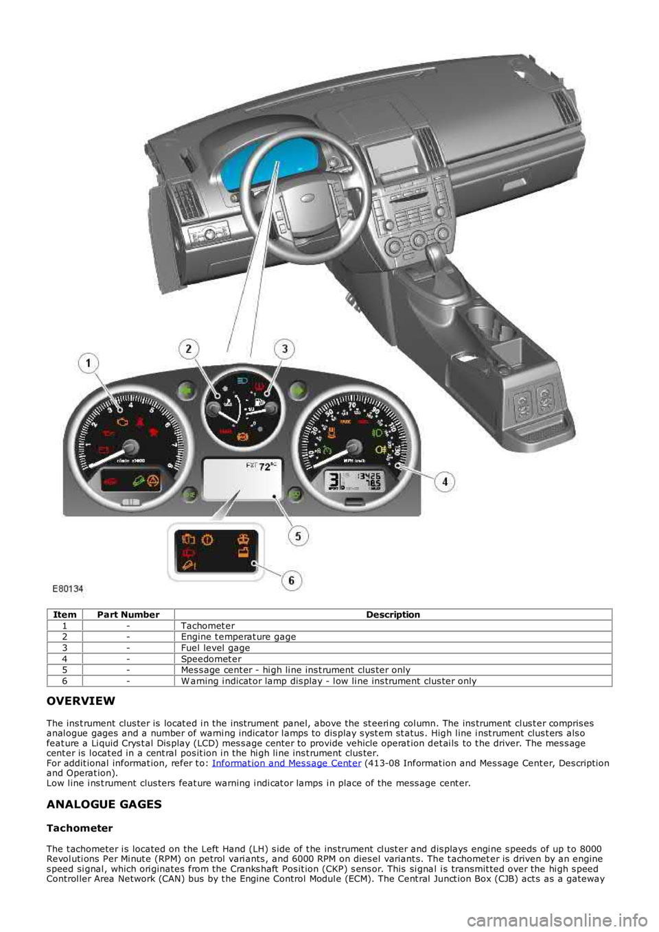
ItemPart NumberDescription
1-Tachomet er2-Engine t emperat ure gage
3-Fuel level gage
4-Speedomet er5-Mes s age cent er - hi gh li ne ins t rument clus ter only
6-W arning i ndicat or lamp dis play - l ow li ne ins t rument clus ter only
OVERVIEW
The ins t rument clus ter is locat ed i n the ins trument panel, above the st eeri ng col umn. The ins trument cl us t er compris esanal ogue gages and a number of warni ng indicator l amps to dis play s yst em st atus . High l ine i nst rument clus t ers als ofeat ure a Li quid Crys t al Dis play (LCD) mes s age cent er to provide vehicle operat ion det ai ls to t he driver. The mes s agecent er is l ocat ed in a cent ral pos it ion i n the hi gh li ne ins t rument clus ter.For addit ional informat ion, refer t o: Informat ion and Mes s age Cent er (413-08 Informat ion and Mes s age Cent er, Des cript ionand Operat ion).Low l ine i ns t rument clus ters feat ure warning i ndi cat or lamps i n place of the mess age cent er.
ANALOGUE GAGES
Tachometer
The t achometer i s located on the Left Hand (LH) s ide of t he ins trument cl ust er and dis plays engi ne s peeds of up t o 8000Revol uti ons Per Mi nut e (RPM) on petrol vari ants , and 6000 RPM on dies el variant s. The t achomet er is driven by an engines peed si gnal , which ori ginates from the Cranks haft Pos it ion (CKP) s ens or. This si gnal i s transmit ted over the hi gh s peedControl ler Area Network (CAN) bus by t he Engine Control Modul e (ECM). The Cent ral Junct ion Box (CJB) act s as a gateway
Page 1768 of 3229
and t ransmit s t he engi ne s peed s i gnal t o the ins trument cl us t er on the medi um s peed CAN bus . The s ignal i s received byt he ins trument cl ust er microproces s or and t he output from the microproces sor dri ves the t achomet er.
Engine Temperature Gage
The engi ne t emperature gage is l ocat ed in the center of t he ins trument cl ust er and is driven by medi um s peed CAN busmes s ages from the CJB. The CJB receives an Engine Coolant Temperat ure (ECT) s i gnal from the ECM over t he high s peedCAN bus when t he vehi cle ent ers power mode 6 (ignit ion on). The needl e pointer pos ition t rans lat es to the followi ngapproximat e t emperatures .
Engine Coolant T emperature °C (°F)
Pointer PositionPetrolDiesel
Igni ti on offIgni ti on offPark40 (104)40 (104)Cold (blue s egment)
75 (167)75 (167)Begi nning of normal
119 (246)113 (235)End of normal125 (257)118 (244)Begi nning of hot (red s egment )
130 (266)123 (253)End of hot
If the ECT s i gnal ri s es above 118 °C (244 °F) on dies el vehicles , or 127 °C (260 °F) on petrol vehi cl es , t he ins t rumentclus ter wi ll il lumi nat e t he high ECT warning i ndi cat or. If the ins trument cl us t er fail s t o receive an ECT s i gnal from the CJB,t he engi ne cool ant t emperat ure gage wi ll move t o t he 'end of hot' posi ti on and t he warning indicator wil l be il lumi nat ed.
Fuel Level Gage
The fuel level gage is l ocat ed in the center of the ins trument cl us t er and di s pl ays fuel tank contents when the vehicle is i npower mode 6. W hen t he ignit ion i s s wit ched off, t he point er returns to the park posi ti on.
Two Magneti c Pas s ive Pos it ion Sens ors (MAPPS) are l ocated in t he s addl e t ype fuel tank, one on eit her s i de. Theres is t ance values for bot h s ensors are measured by t he CJB through a series of hardwi red connect ions. The CJB convertsboth val ues t o medi um s peed CAN mes s ages for delivery to the i nst rument clus t er. The ins trument cl ust er uses the 2 CANbus mes sages t o calculate the t otal amount of fuel in bot h halves of the tank. The ins trument cl us t er wil l al so damp t het ot al fuel val ue t o eli minate cons tant point er movement due t o fuel moving in t he t ank.
The fol lowing table shows t he approximat e fuel t ank level and t he respecti ve needle poi nter pos it ion.
Fuel Quantity Liters (US gallons)
Pointer PositionPetrolDiesel0 (0)0 (0)Mechanical zero
1 (0.2)2.5 (0.6)Below empt y
2.8 (0.7)3.8 (1)Indicat ed empty11.9 (3.1)10.3 (2.7)Low fuel level indicator i lluminated
13.9 (3.7)12.3 (3.2)Low fuel level indicator exti ngui shed
16.9 (4.5)16.7 (4.4)Quart er full33.8 (8.9)33.4 (8.8)Half ful l
50.8 (13.4)50 (13.2)Three quart ers full
66.9 (17.7)68 (18)Indicat ed full70.5 (18.6)70.5 (18.6)Over full
If the i nst rument clus ter fails to recei ve t he fuel level si gnal s from t he CJB t he fuel level gage will move to t he empt yposi ti on and t he low fuel level i ndi cat or wil l be il lumi nat ed.
Speedometer
The s peedomet er i s located on the Ri ght Hand (RH) s ide of t he clus ter and i s avai lable i n 3 variants :
Major s cal e mph, mi nor s cale ki lomet ers per hour (kph)Major s cal e kph, minor s cal e mphMajor s cal e kph only.
The s peedomet er i s dri ven by medium speed CAN bus si gnal s transmit ted by t he CJB. The vehicl e s peed s i gnal is providedt o the CJB by the Ant i-lock Brake Sys tem (ABS) module over t he high s peed CAN bus and is an average of al l 4 wheels peed sens or si gnal s.
The s peedomet er al so incorporat es the odomet er.For addit ional informat ion, refer t o: Informat ion and Mes s age Cent er (413-08 Informat ion and Mes s age Cent er, Des cript ionand Operat ion).
WARNING INDICATORS
Page 1769 of 3229
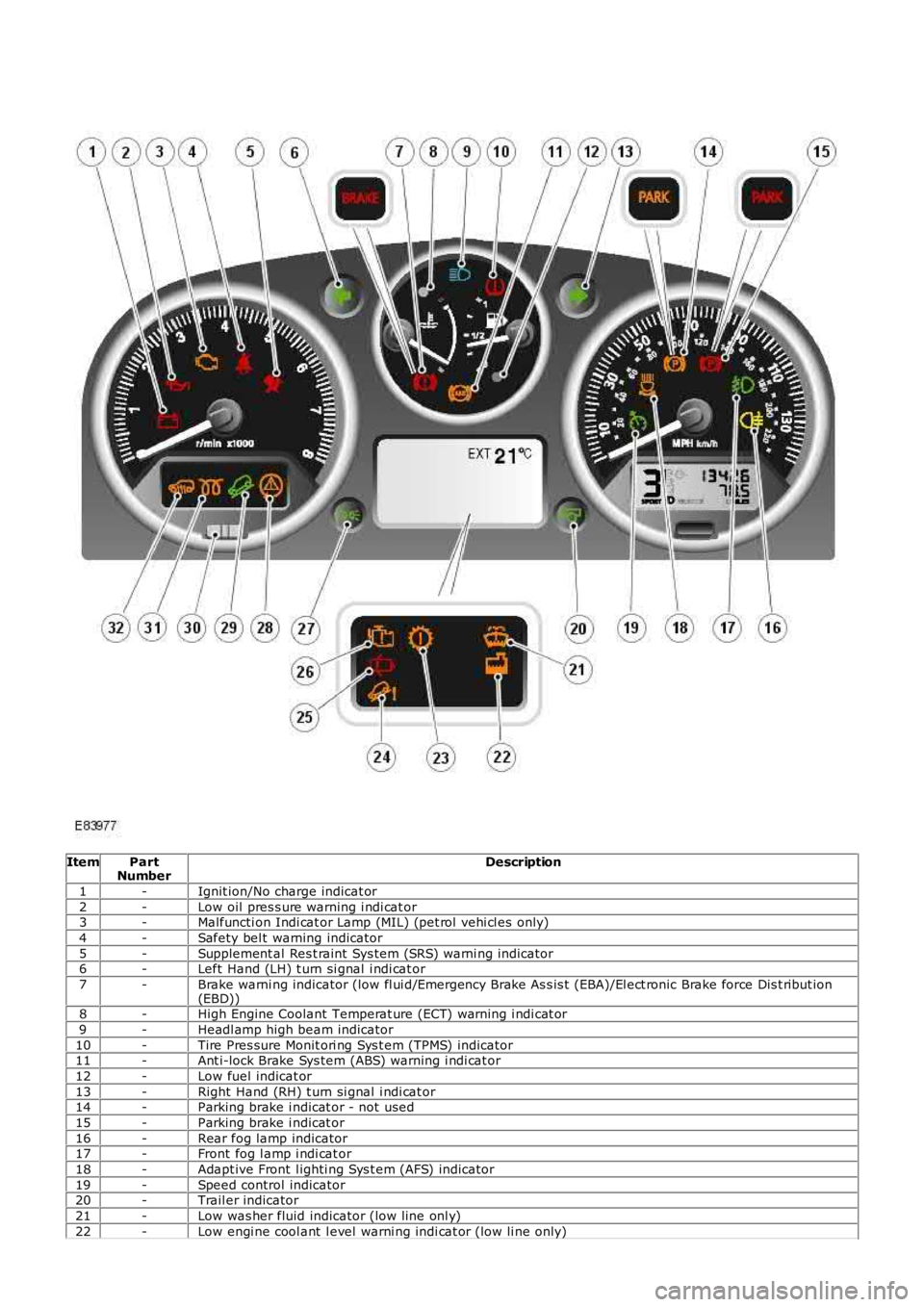
ItemPartNumberDescription
1-Ignit ion/No charge indicat or
2-Low oil pres s ure warning i ndi cat or3-Malfuncti on Indi cat or Lamp (MIL) (pet rol vehi cl es only)
4-Safety bel t warning indicator
5-Supplement al Res t raint Sys tem (SRS) warni ng indicator6-Left Hand (LH) t urn si gnal i ndi cat or
7-Brake warni ng indicator (low fl ui d/Emergency Brake As s is t (EBA)/El ect ronic Brake force Dis t ribut ion(EBD))8-High Engine Coolant Temperat ure (ECT) warning i ndi cat or
9-Headl amp high beam indicator
10-Tire Pres sure Monit ori ng Sys t em (TPMS) indicator11-Ant i-lock Brake Sys tem (ABS) warning i ndi cat or
12-Low fuel indicat or
13-Right Hand (RH) t urn si gnal i ndi cat or14-Parking brake i ndicat or - not used
15-Parking brake i ndicat or
16-Rear fog lamp indicator17-Front fog l amp i ndi cat or
18-Adapt ive Front l ighti ng Sys t em (AFS) indicator
19-Speed control indicator20-Trail er indicator
21-Low was her fluid indicator (low line onl y)
22-Low engi ne cool ant l evel warni ng indi cat or (low li ne only)
Page 1770 of 3229
23-Transmis s ion warni ng indi cat or (low li ne only)
24-Hil l Des cent Cont rol (HDC) fault i ndi cat or (l ow li ne only)
25-Door open i ndi cat or (l ow li ne only)26-Engi ne management s yst em warning i ndicat or (l ow l ine only)
27-Side l amp indicat or
28-Dynami c Stabil it y Control (DSC) indicat or29-HDC acti ve indicator
30-Ant i-t heft alarm i ndi cat or
31-Glow pl ug indicat or (dies el vehicles onl y)32-Fuel fired boos ter heater i ndi cat or (i f fi tt ed)
The low li ne ins trument cl ust er cont ains 39 i ndi cat ors , the hi gh li ne ins t rument clus ter 27. The indicators in hi gh li neins t rument clus ters are s upplemented by mess ages in the mess age cent er.For addit ional informat ion, refer t o: Informat ion and Mes s age Cent er (413-08 Informat ion and Mes s age Cent er, Des cript ionand Operat ion).
The warni ng indicators can be s plit i nto 2 groups ; sel f cont roll ed and ext ernall y cont rol led. Self cont rol led warni ngindicat ors are dependent on software l ogi c wit hin t he i ns t rument clus ter for act ivati on. External ly controll ed indicators ares uppl ied wi th current from anot her s yst em cont roll ing module or ill uminat ed by the ins trument cl us t er on receipt of amedium s peed CAN bus mes sage from the CJB.
Ignition/No Charge Indicator
The ignit ion/no charge indicator i s cont rol led by t he ins t rument clus ter s oft ware and i ll uminated by medium speed CAN buss ignals from the ECM via t he CJB. The indicator il lumi nat es i n a red col or when the vehicle ent ers power mode 6 and isexti nguis hed when t he engine i s s tart ed.
If the i ndi cat or remai ns ill uminat ed aft er the engine has s t art ed or ill uminat es when drivi ng, t he alt ernator charge out puthas fai led.
Low Oil Pressure Warning Indicator
The low oil pres s ure warning i ndi cat or is i lluminated by t he i ns t rument clus ter on recei pt of a medium speed CAN buss ignal from t he CJB. The s ignal ori gi nates i n t he ECM and is generat ed by t he engi ne oil l evel s ens or on petrol vehicl es andt he engi ne oil pres s ure s ensor on di esel vehi cles .
The indicat or i ll uminates i n a red color when t he vehi cl e enters power mode 6 for a 3 s econd bulb check. If t he bul bs ubs equent ly ill uminat es when the engine is runni ng, t he engine s houl d be s t opped i mmediat ely i t is s afe to do s o.
Malfunction Indicator Lamp
The Malfunct ion Indicat or Lamp (MIL) i s il lumi nat ed by t he ins trument cl ust er on receipt of a medi um s peed CAN bus s ignalfrom the CJB. The si gnal originat es in t he ECM and i s generated if an On-Board Diagnos ti c (OBD) fault has been det ectedwhich wi ll caus e excess i ve emis s ions output. Thi s may rel ate to ei ther an engine management or trans mi ss i on fault .
The MIL is ill uminat ed in an amber color when t he vehi cl e enters power mode 6 for a 3 s econd bul b check. The bul b checkin thi s ins tance is carri ed out by the ECM vi a t he CJB, not t he ins trument cl ust er. If t he MIL subs equent ly i lluminates t hevehi cl e s houl d be i nterrogated us ing t he Land Rover approved diagnost ic sys tem at the earli es t opport uni ty.
Safety Belt Warning Indicator
The s afety bel t warni ng indicator wi ll il lumi nat e i n a red color on receipt of a medi um s peed CAN bus s ignal from t he CJB.The s ignal origi nat es in the Res traint s Cont rol Module (RCM), which monit ors the s t at us of t he occupant clas s ificati ons ys t em and s wi tches located i n t he s afety bel t buckles .
Three vari ati ons of warning are avai lable depending on vehicle confi gurati on:
Reminder (al l vehicl es except Nort h Ameri can Specificati on (NAS) vehicles )Federal Mot or Vehi cl e Safet y Standard (FMVSS) 208 remi nder (NAS vehi cles only)Belt Mi nder
The condi ti ons for s afety bel t warning indicator il lumi nat ion are as follows :
Reminder
Vehicle i n power mode 6Dri vers s afet y belt not s ecured in i ts buckleLarge pas senger det ect ed i n front pas s enger s eat wit h an uns ecured safety bel t.
The warni ng indicator wi ll remai n i lluminated unt il eit her t he i gni ti on is swi tched off or condi ti ons 2 and 3 no longer exis t .
FMVSS-208 Reminder
Vehicle i n power mode 6Dri vers s afet y belt not s ecured in i ts buckle.
The warni ng indicator wi ll remai n i lluminated for 65 s econds and wil l be accompanied by a si ngl e 6 second chi me from theins t rument clus ter s ounder.
• NOTE: The warni ng indicator and chime wil l not acti vat e i f thes e condi ti ons aris e 75 seconds aft er t he vehicle hasentered power mode 6.
The warni ng indicator wi ll be exti ngui shed and t he s ounder cancell ed if t he i gni ti on is s wi tched off or t he dri ver's s afet ybelt i s s ecured in i ts buckle.
Belt Mi nder