2006 LAND ROVER FRELANDER 2 steering
[x] Cancel search: steeringPage 113 of 3229

Publi s hed: 03-May-2011
General Information - Diagnostic Trouble Code (DTC) IndexDTC:
Instrument Cluster (IPC)
Des cript ion and Operat ion
• NOTE: If a cont rol module or component i s s uspect and the vehicl e remai ns under manufacturer warrant y, refer t o t heW arranty Pol icy and Procedures manual (s ect ion B1.2), or determine i f any pri or approval program is i n operat ion, beforet he replacement of a component.
• NOTE: Generic scan t ool s may not read the codes li st ed, or may read only 5-digi t codes . Match t he 5 digi ts from t he s cant ool t o t he fi rs t 5 di gi ts of the 7-digit code li s ted t o i dent ify the fault (the last 2 digi ts gi ve ext ra informati on read by themanufacturer-approved di agnos ti c s ys t em).
• NOTE: W hen performing volt age or res is t ance t est s , always use a digi tal mult imeter (DMM) accurat e t o t hree deci malplaces, and wi th an up-t o-date cal ibrat ion cert ificate. W hen tes ti ng res is t ance al ways take t he res is t ance of t he DMMleads i nt o account .
• NOTE: Check and recti fy bas ic faul ts before beginni ng diagnos t ic rout ines i nvol vi ng pinpoint t es t s.
• NOTE: Ins pect connect ors for s igns of water ingres s , and pins for damage and/or corros ion.
• NOTE: If DTCs are recorded and, aft er performi ng the pi npoi nt tes ts , a fault is not present , an int ermi tt ent concern maybe t he caus e. Always check for loose connect ions and corroded terminals .
Des cript ion And Operat ion
For a detail ed descripti on of the ins trument cl us t er sys tem, refer t o t he rel evant Descripti on and Operat ion s ecti on in t heworks hop manual .For addit ional informat ion, refer t o: Ins t rument Clus ter (413-01 Inst rument Cl us t er, Des cript ion and Operat ion).
Instrument cluster control module (IPC )DT CDescriptionPossible CauseAction
B1184-62Steering Column LockOutputSignal compare fai lureCheck st eering lock power from CJB. Check CJB forDTCs and refer to relevant DTC Index.For addi ti onal informat ion, refer t o:Communicati ons Network (418-00 Modul eCommunicati ons Network, Di agnos is and Tes t ing).
B1A14-96RCM W arning LampLight Emit t ing Di ode (LED)fai lureIns t all a new ins trument cl us t er.For addi ti onal informat ion, refer t o: Ins t rumentClus t er (413-01 Inst rument Cl us t er, Removal andIns t allat ion).Refer t o t he new module/component ins tall ati onnote at the t op of the DTC Index
B1A84-41Car Configurat ion Dat aFlas h download checks umerrorIns t all lat est avail abl e l evel of software us ing t hemanufacturer approved di agnos ti c s ys t em
B1A84-81Car Configurat ion Dat aInvali d Car Configurat iondata recei vedCheck/amend Car Configurat ion Fil e us ingmanufacturer approved di agnos ti c s ys t em
C2002-62Odometer TamperedDTC s et when one or mores tored odomet er val ue doesnot match
Clear DTC, cycle ignit ion and re-t est
U0010-87Medium Speed CANCommunicati on BusMult ipl e los s of CAN dat a toother s yst emsCarry out pinpoint tes t s ass ociat ed wit h t his DTCus ing t he manufacturer approved diagnos ti cs yst em
U0010-88Medium Speed CANCommunicati on BusBreak i n connecti on to busCarry out pinpoint tes t s ass ociat ed wit h t his DTCus ing t he manufacturer approved diagnos ti cs yst emU0140-08Lost Communi cat ionW i th Body Cont rolModule
No mes s ages recei ved fromCJB for great er than t imeoutperi od
Carry out pinpoint tes t s ass ociat ed wit h t his DTCus ing t he manufacturer approved diagnos ti cs yst em
U0208-08Lost Communi cat ionW i th "Seat Cont rolModule A"
No mes s ages recei ved fromDSM for greater t hant imeout period
Check DSM for DTCs and refer t o rel evant DTCIndex.For addi ti onal informat ion, refer t o: Seat s (501-10Seati ng, Di agnos is and Tes ti ng).Carry out CAN Net work i nt egri ty t es ts us ing themanufacturer approved di agnos ti c s ys t emU0300-62Int ernal Cont rol ModuleSoft ware Incompat ibi lit yConfigurat ion dat a receivedis di fferent from the s t oreddata
Check correct ins trument cl us t er is i nst all ed
U3000-46Control ModuleEEPROM writ e errorCheck power and ground circui ts to the i nst rumentclus ter, cl ear DTC and re-tes t. If DTC remains ,ins t al l a new i nst rument clus t er.For addi ti onal informat ion, refer t o: Ins t rumentClus t er (413-01 Inst rument Cl us t er, Removal andIns t allat ion).Refer t o t he new module/component ins tall ati onnote at the t op of the DTC Index
Page 127 of 3229
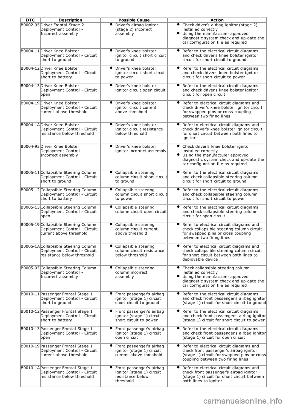
DT C
Description Possible Cause Action
B0002-95 Dri ver Front al Stage 2
Deployment Cont rol -
Incorrect as s embly Driver's airbag ignit or
(s tage 2) i ncorrect
as s embly Check dri ver’s ai rbag i gni tor (s tage 2)
ins tall ed correct ly Usi ng t he manufact urer approved
di agnos t ic s yst em check and up-date the
car configurat ion fil e as requi red B0004-11
Dri ver Knee Bol st er
Deployment Cont rol - Circui t
s hort t o ground Driver's knee bols ter
ignit or ci rcuit s hort circui t
to ground Refer to the el ect ri cal circui t di agrams
and check dri ver's knee bols ter i gni tor
ci rcuit for short ci rcuit t o ground B0004-12
Dri ver Knee Bol st er
Deployment Cont rol - Circui t
s hort t o batt ery Driver's knee bols ter
ignit or ci rcuit s hort circui t
to power Refer to the el ect ri cal circui t di agrams
and check dri ver's knee bols ter i gni tor
ci rcuit for short ci rcuit t o power B0004-13
Dri ver Knee Bol st er
Deployment Cont rol - Circui t
open Driver's knee bols ter
ignit or ci rcuit open circuit Refer to the el ect ri cal circui t di agrams
and check dri ver's knee bols ter i gni tor
ci rcuit for open circui t B0004-19
Dri ver Knee Bol st er
Deployment Cont rol - Circui t
current above threshold Driver's knee bols ter
ignit or ci rcuit current
above t hres hol d Refer to el ect ri cal circui t diagrams and
check dri ver’s knee bols ter i gni tor circui t
for s wapped pi ns or cross coupli ng
bet ween t wo fi ri ng li nes B0004-1A
Dri ver Knee Bol st er
Deployment Cont rol - Circui t
res is t ance bel ow t hreshol d Driver's knee bols ter
ignit or ci rcuit res i st ance
bel ow t hres hol d Refer to el ect ri cal circui t diagrams and
check dri ver's knee bols ter i gni tor circui t
for s hort circuit bet ween both l ines t o
ignit or B0004-95
Dri ver Knee Bol st er
Deployment Cont rol -
Incorrect as s embly Driver’s knee bols ter
ignit or i ncorrect ass embly Check dri ver’s knee bols t er ignit or
ins tall ed correct ly Usi ng t he manufact urer approved
di agnos t ic s yst em check and up-date the
car configurat ion fil e as requi red B0005-11
Coll aps ibl e Steering Column
Deployment Cont rol - Circui t
s hort t o ground Col laps ible st eering
column circuit s hort ci rcuit
to ground Refer to the el ect ri cal circui t di agrams
and check col laps ible st eeri ng col umn
ci rcuit for short ci rcuit t o ground B0005-12
Coll aps ibl e Steering Column
Deployment Cont rol - Circui t
s hort t o batt ery Col laps ible st eering
column circuit s hort ci rcuit
to power Refer to the el ect ri cal circui t di agrams
and check col laps ible st eeri ng col umn
ci rcuit for short ci rcuit t o power B0005-13
Coll aps ibl e Steering Column
Deployment Cont rol - Circui t
open Col laps ible st eering
column circuit open circui t Refer to the el ect ri cal circui t di agrams
and check col laps ible st eeri ng col umn
ci rcuit for open circui t B0005-19
Coll aps ibl e Steering Column
Deployment Cont rol - Circui t
current above threshold Col laps ible st eering
column circuit current
above t hres hol d Refer to el ect ri cal circui t diagrams and
check col laps ible st eeri ng col umn circui t
for s wapped pi ns or cross coupli ng
bet ween t wo fi ri ng li nes B0005-1A
Coll aps ibl e Steering Column
Deployment Cont rol - Circui t
res is t ance bel ow t hreshol d Col laps ible st eering
column circuit res is tance
bel ow t hres hol d Refer to el ect ri cal circui t diagrams and
check col laps ible st eeri ng col umn circui t
for s hort circuit bet ween both l ines t o
depl oyable device B0005-95
Coll aps ibl e Steering Column
Deployment Cont rol -
Incorrect as s embly Col laps ible st eering
column incorrect
as s embly Check collaps ibl e s teeri ng col umn
ins tall ed correct ly Usi ng t he manufact urer approved
di agnos t ic s yst em check and up-date the
car configurat ion fil e as requi red B0010-11
Pass enger Front al Stage 1
Deployment Cont rol - Circui t
s hort t o ground Front pas s enger's airbag
ignit or (s tage 1) circui t
short ci rcuit t o ground Refer to the el ect ri cal circui t di agrams
and check front pas s enger's airbag ignit or
(s t age 1) ci rcuit for s hort circui t t o ground B0010-12
Pass enger Front al Stage 1
Deployment Cont rol - Circui t
s hort t o batt ery Front pas s enger's airbag
ignit or (s tage 1) circui t
short ci rcuit t o power Refer to the el ect ri cal circui t di agrams
and check front pas s enger's airbag ignit or
(s t age 1) ci rcuit for s hort circui t t o power B0010-13
Pass enger Front al Stage 1
Deployment Cont rol - Circui t
open Front pas s enger's airbag
ignit or (s tage 1) circui t
open circui t Refer to the el ect ri cal circui t di agrams
and check front pas s enger's airbag ignit or
(s t age 1) ci rcuit for open circui t B0010-19
Pass enger Front al Stage 1
Deployment Cont rol - Circui t
current above threshold Front pas s enger's airbag
ignit or (s tage 1) circui t
current above t hres hold Refer to el ect ri cal circui t diagrams and
check front pas s enger’s airbag ignit or
(s t age 1) ci rcuit for s wapped pins or cros s
coupli ng bet ween t wo firing l ines B0010-1A
Pass enger Front al Stage 1
Deployment Cont rol - Circui t
res is t ance bel ow t hreshol d Front pas s enger's airbag
ignit or (s tage 1) circui t
res is tance below
thres hold Refer to el ect ri cal circui t diagrams and
check front pas s enger's airbag ignit or
(s t age 1) ci rcuit for s hort circui t between
bot h l ines t o ignit or
Page 138 of 3229
Publ is hed: 27-Apr-2011
General Information - Diagnostic Trouble Code (DTC) IndexDTC: Steering
Angle Sensor Module (SASM)
Des cript ion and Operat ion
• NOTE: If a cont rol module or component i s s uspect and the vehicl e remai ns under manufacturer warrant y, refer t o t heW arranty Pol icy and Procedures manual (s ect ion B1.2), or determine i f any pri or approval program is i n operat ion, beforet he replacement of a component.
• NOTE: Generic scan t ool s may not read the codes li st ed, or may read only 5-digi t codes . Match t he 5 digi ts from t he s cant ool t o t he fi rs t 5 di gi ts of the 7-digit code li s ted t o i dent ify the fault (the last 2 digi ts gi ve ext ra informati on read by themanufacturer-approved di agnos ti c s ys t em).
• NOTE: W hen performing volt age or res is t ance t est s , always use a digi tal mult imeter (DMM) accurat e t o t hree deci malplaces, and wi th an up-t o-date cal ibrat ion cert ificate. W hen tes ti ng res is t ance al ways take t he res is t ance of t he DMMleads i nt o account .
• NOTE: Check and recti fy bas ic faul ts before beginni ng diagnos t ic rout ines i nvol vi ng pinpoint t es t s.
• NOTE: Ins pect connect ors for s igns of water ingres s , and pins for damage and/or corros ion.
• NOTE: If DTCs are recorded and, aft er performi ng the pi npoi nt tes ts , a fault is not present , an int ermi tt ent concern maybe t he caus e. Always check for loose connect ions and corroded terminals .
Des cript ion And Operat ion
For a detail ed descripti on of the ant i lock cont rol s tabil it y s yst em, refer to the relevant Des cri pt ion and Operati on s ect ionin the workshop manual.For addit ional informat ion, refer t o: Anti -Lock Cont rol - St abi li ty As s is t (206-09C Anti -Lock Cont rol - St abi lit y As s is t,Des cript ion and Operat ion).
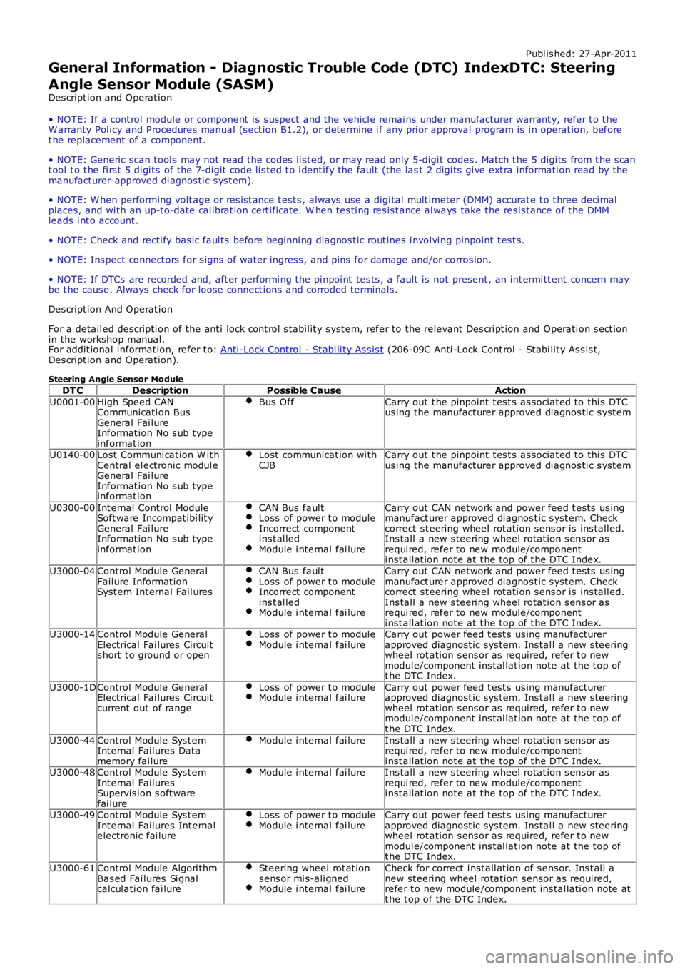
Steering Angle Sensor Module
DT CDescriptionPossible CauseAction
U0001-00High Speed CANCommunicati on BusGeneral Fai lureInformat ion No s ub typeinformat ion
Bus OffCarry out t he pinpoint t es t s as sociat ed to thi s DTCus ing the manufact urer approved di agnos ti c s yst em
U0140-00Lost Communi cat ion W it hCentral el ect ronic modul eGeneral Fai lureInformat ion No s ub typeinformat ion
Lost communicat ion wi thCJBCarry out t he pinpoint t es t s as sociat ed to thi s DTCus ing the manufact urer approved di agnos ti c s yst em
U0300-00Int ernal Control ModuleSoft ware Incompat ibi lit yGeneral Fai lureInformat ion No s ub typeinformat ion
CAN Bus faul tLoss of power t o moduleIncorrect componentins t al ledModule i nternal fai lure
Carry out CAN net work and power feed t es ts us ingmanufact urer approved di agnos t ic s yst em. Checkcorrect s t eering wheel rot ati on s ens or is ins tall ed.Ins tall a new s teeri ng wheel rotat ion s ens or asrequi red, refer to new module/componenti nst all at ion not e at t he top of t he DTC Index.
U3000-04Control Module GeneralFailure Informat ionSyst em Int ernal Fail ures
CAN Bus faul tLoss of power t o moduleIncorrect componentins t al ledModule i nternal fai lure
Carry out CAN net work and power feed t es ts us ingmanufact urer approved di agnos t ic s yst em. Checkcorrect s t eering wheel rot ati on s ens or is ins tall ed.Ins tall a new s teeri ng wheel rotat ion s ens or asrequi red, refer to new module/componenti nst all at ion not e at t he top of t he DTC Index.U3000-14Control Module GeneralElectrical Fai lures Ci rcuits hort t o ground or open
Loss of power t o moduleModule i nternal fai lureCarry out power feed t est s us ing manufact urerapproved diagnost ic sys tem. Ins tal l a new s teeringwheel rot ati on s ens or as required, refer t o newmodul e/component ins t al lat ion note at the t op oft he DTC Index.
U3000-1DControl Module GeneralElectrical Fai lures Ci rcuitcurrent out of range
Loss of power t o moduleModule i nternal fai lureCarry out power feed t est s us ing manufact urerapproved diagnost ic sys tem. Ins tal l a new s teeringwheel rot ati on s ens or as required, refer t o newmodul e/component ins t al lat ion note at the t op oft he DTC Index.
U3000-44Control Module Sys t emInt ernal Failures Datamemory fai lure
Module i nternal fai lureIns tall a new s teeri ng wheel rotat ion s ens or asrequi red, refer to new module/componenti nst all at ion not e at t he top of t he DTC Index.U3000-48Control Module Sys t emInt ernal FailuresSupervis ion s oft warefai lure
Module i nternal fai lureIns tall a new s teeri ng wheel rotat ion s ens or asrequi red, refer to new module/componenti nst all at ion not e at t he top of t he DTC Index.
U3000-49Control Module Sys t emInt ernal Failures Int ernalelectronic fai lure
Loss of power t o moduleModule i nternal fai lureCarry out power feed t est s us ing manufact urerapproved diagnost ic sys tem. Ins tal l a new s teeringwheel rot ati on s ens or as required, refer t o newmodul e/component ins t al lat ion note at the t op oft he DTC Index.
U3000-61Control Module Algori thmBas ed Fai lures Si gnalcalcul ati on fai lure
Steering wheel rot at ions ens or mi s-ali gnedModule i nternal fai lure
Check for correct i nst all at ion of s ens or. Ins t al l anew st eeri ng wheel rotat ion s ensor as requi red,refer t o new module/component ins tal lati on note att he t op of the DTC Index.
Page 139 of 3229
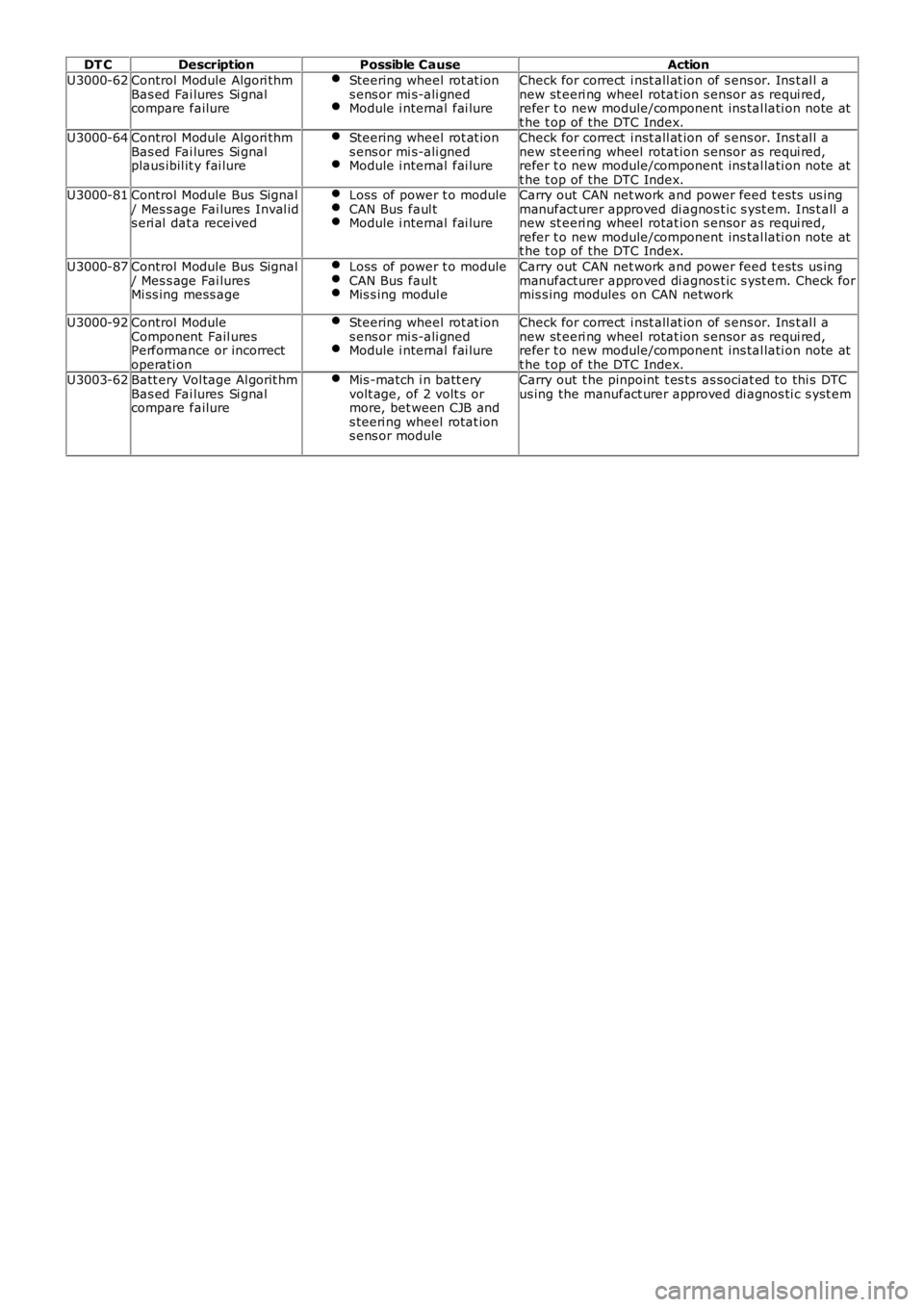
DT CDescriptionPossible CauseAction
U3000-62Control Module Algori thmBas ed Fai lures Si gnalcompare failure
Steering wheel rot at ions ens or mi s-ali gnedModule i nternal fai lure
Check for correct i nst all at ion of s ens or. Ins t al l anew st eeri ng wheel rotat ion s ensor as requi red,refer t o new module/component ins tal lati on note att he t op of the DTC Index.U3000-64Control Module Algori thmBas ed Fai lures Si gnalplaus ibil it y fai lure
Steering wheel rot at ions ens or mi s-ali gnedModule i nternal fai lure
Check for correct i nst all at ion of s ens or. Ins t al l anew st eeri ng wheel rotat ion s ensor as requi red,refer t o new module/component ins tal lati on note att he t op of the DTC Index.U3000-81Control Module Bus Signal/ Mes s age Fai lures Inval ids eri al dat a received
Loss of power t o moduleCAN Bus faul tModule i nternal fai lure
Carry out CAN net work and power feed t es ts us ingmanufact urer approved di agnos t ic s yst em. Ins t all anew st eeri ng wheel rotat ion s ensor as requi red,refer t o new module/component ins tal lati on note att he t op of the DTC Index.
U3000-87Control Module Bus Signal/ Mes s age Fai luresMi ss ing mess age
Loss of power t o moduleCAN Bus faul tMis s ing modul e
Carry out CAN net work and power feed t es ts us ingmanufact urer approved di agnos t ic s yst em. Check formis s ing modules on CAN network
U3000-92Control ModuleComponent Fail uresPerformance or incorrectoperati on
Steering wheel rot at ions ens or mi s-ali gnedModule i nternal fai lure
Check for correct i nst all at ion of s ens or. Ins t al l anew st eeri ng wheel rotat ion s ensor as requi red,refer t o new module/component ins tal lati on note att he t op of the DTC Index.U3003-62Batt ery Vol tage Al gorit hmBas ed Fai lures Si gnalcompare failure
Mis -match i n batt eryvolt age, of 2 volt s ormore, bet ween CJB ands teeri ng wheel rotat ions ens or module
Carry out t he pinpoint t es t s as sociat ed to thi s DTCus ing the manufact urer approved di agnos ti c s yst em
Page 163 of 3229
Publ is hed: 24-Jun-2011
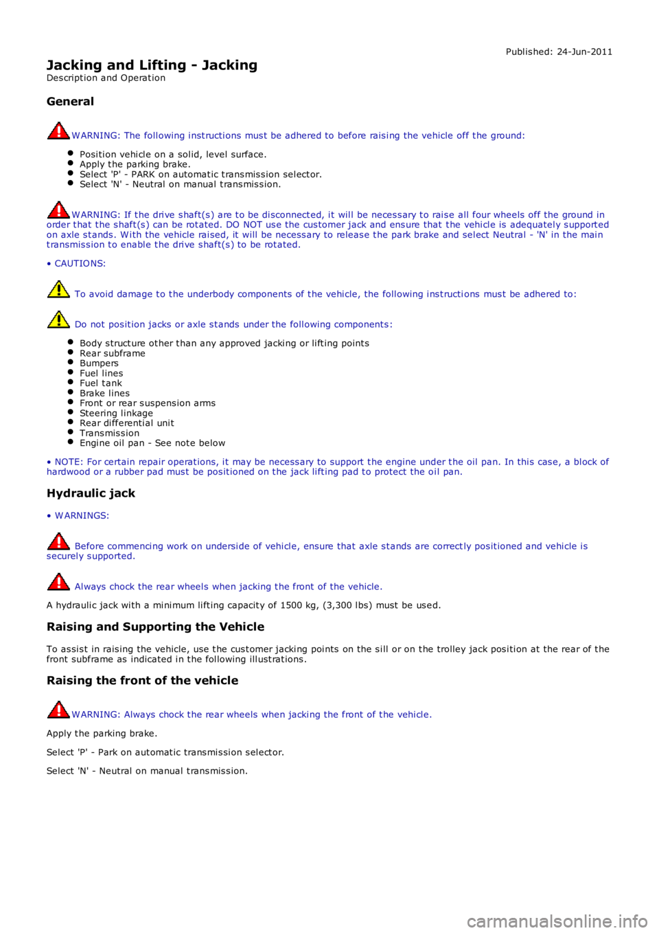
Jacking and Lifting - Jacking
Des cript ion and Operat ion
General
W ARNING: The foll owing i nst ructi ons mus t be adhered to before rais i ng the vehicle off t he ground:
Posi ti on vehi cl e on a sol id, level surface.Apply t he parking brake.Select 'P' - PARK on automat ic t rans mis s ion sel ect or.Select 'N' - Neutral on manual t rans mis s ion.
W ARNING: If t he dri ve s haft(s ) are t o be di sconnect ed, i t wil l be neces s ary t o rai s e all four wheels off the ground inorder t hat t he s haft (s ) can be rot ated. DO NOT us e the cus tomer jack and ens ure that t he vehi cl e is adequatel y s upport edon axle s t ands . W i th the vehicle rai sed, it will be necess ary to releas e t he park brake and sel ect Neutral - 'N' in the mai nt ransmis s ion t o enabl e t he dri ve s haft(s ) to be rot ated.
• CAUTIO NS:
To avoid damage t o t he underbody components of t he vehi cle, the foll owing i ns t ructions mus t be adhered to:
Do not pos it ion jacks or axle s t ands under the foll owing component s :
Body s truct ure ot her t han any approved jacki ng or li ft ing point sRear subframeBumpersFuel l inesFuel t ankBrake l inesFront or rear s uspens ion armsSteering l inkageRear di fferenti al uni tTrans mis s ionEngi ne oil pan - See not e below
• NOTE: For certain repair operat ions, i t may be necess ary to support t he engine under t he oil pan. In thi s cas e, a bl ock ofhardwood or a rubber pad mus t be pos it ioned on t he jack li ft ing pad t o protect the oi l pan.
Hydraulic jack
• W ARNINGS:
Before commenci ng work on undersi de of vehi cl e, ens ure that axle s t ands are correctly pos it ioned and vehi cle i ss ecurel y s upported.
Al ways chock the rear wheel s when jacking t he front of the vehicle.
A hydrauli c jack wi th a mi ni mum li ft ing capacit y of 1500 kg, (3,300 l bs) must be us ed.
Raising and Supporting the Vehicle
To as si s t in rais ing the vehicle, us e t he cus t omer jacki ng poi nts on the s i ll or on t he trolley jack pos i ti on at the rear of t hefront subframe as indicated i n t he fol lowing ill ust rat ions .
Raising the front of the vehicle
W ARNING: Always chock t he rear wheels when jacki ng the front of t he vehi cl e.
Apply t he parking brake.
Select 'P' - Park on aut omat ic trans mi s si on s el ect or.
Select 'N' - Neutral on manual t rans mis s ion.
Page 178 of 3229
Fluid levels
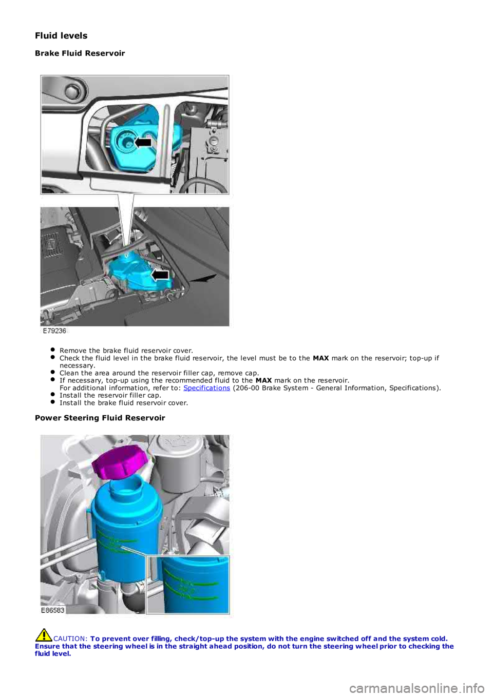
Brake Fluid Reservoir
Remove the brake fl uid reservoi r cover.Check t he fluid level i n t he brake fluid res ervoir, the l evel mus t be t o t he MAX mark on the reservoi r; t op-up i fneces s ary.Clean t he area around the res ervoi r fi ll er cap, remove cap.If necess ary, t op-up us ing t he recommended fluid to the MAX mark on t he res ervoir.For addit ional informat ion, refer t o: Specificati ons (206-00 Brake Syst em - General Informati on, Speci fi cat ions ).Ins t all the res ervoir fill er cap.Ins t all the brake fl uid reservoi r cover.
Power Steering Fluid Reservoir
CAUTION: T o prevent over filling, check/top-up the system with the engine sw itched off and the system cold.Ensure that the steering wheel is in the straight ahead position, do not turn the steering w heel prior to checking thefluid level.
Page 180 of 3229
1. Check for free play i n all s uspens ion and body mounti ng rubbers .
2. Check condit ion of s uspens ion rubber boot s and gait ers .
Fuel System
Check fuel sys tem pipes , hos es and unions for chafi ng, l eaks and corros ion.
Electrical Harnesses
Check al l el ect ri cal harnes s es for chafing.
Oil/Fluid Leaks
Check for oil/fluid leaks .
Power Steering
Check power s teering rod bal l joi nt fixi ngs , gait ers and condi ti on of bal l joi nt s and dus t covers .Check power s teering pipes , hos es and unions for chafi ng, leaks and corros ion.
Exhaust System
Check exhaust s ys tem for l eaks , securi ty and damage.
Fault Lamp(s)
If fault l amp(s ) are ill uminat ed, t est the as s oci at ed s yst em us i ng T4 and report findings .
Road Test
Carry out road t est of vehicle.For addit ional informat ion, refer t o: Road/Roller Tes ti ng (100-00 General Informati on, Des cri pt ion and Operati on).
General
Endors e Service Record.Report any unus ual features of vehi cl e condi ti on and any addi ti onal work required.
Vehicles Operating Under Arduous Conditions
Service i ntervals for vehi cles operati ng under arduous condi ti ons are det ailed bel ow.
Braking system
CAUTION: When vehicles are operating under arduous conditions, the following service items must be carriedout every 3 months or 3,750 miles (6,000 km).
Ins pect front brake pads for wear.Ins pect rear pads for wear.Check brake cal ipers for s igns of fl ui d l eaks .Check brake dis cs for condi ti on.Check al l brake boos t er and brake s ys t em pipes and hos es for condi ti on, chafi ng and leaks.Clean road wheel hub s pigot s and appl y greas e, Land Rover Part Number RY L 105020 t o t he wheel mat ing surfaceof each s pigot .
Brake Fluid Replacement
CAUTION: When vehicles are operating under arduous conditions, the following service item must be carried outevery 2 Years or 30,000 miles (48,000 km).
Replace brake fluid.
Road Wheel Speed Sensors
CAUTION: When vehicles are operating under arduous conditions, the following service item must be carried outevery 3 months or 3,750 miles (6,000 km).
Ins pect the road wheel s peed s ens or harness es for damage.
Engine Oil and Filter
CAUTION: When vehicles are operating under arduous conditions, the following service item must be carried outevery 3 months or 3,750 miles (6,000 km).
Renew engi ne oil and fil ter.
Page 189 of 3229
1. Every 10 years or 150,000 miles (240,000 km): Repl ace the cams haft t imi ng belt , tens ioner and pul ley.
For addit ional informat ion, refer t o:
Timi ng Belt (303-01B Engi ne - TD4 2.2L Dies el, Removal and Inst all ati on).
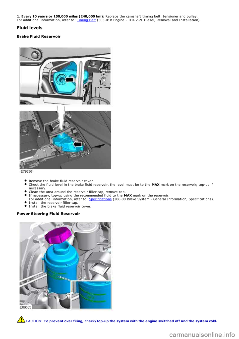
Fluid levels
Brake Fluid Reservoir Remove the brake fl uid reservoi r cover.
Check t he fluid level i n t he brake fluid res ervoir, the l evel mus t be t o t he
MAX mark on the reservoi r; t op-up i f
neces s ary. Clean t he area around the res ervoi r fi ll er cap, remove cap.
If necess ary, t op-up us ing t he recommended fluid to the
MAX mark on t he res ervoir.
For addit ional informat ion, refer t o: Specificati ons (206-00 Brake Syst em - General Informati on, Speci fi cat ions ).
Ins t all the res ervoir fill er cap.
Ins t all the brake fl uid reservoi r cover.
Power Steering Fluid Reservoir
CAUTION:
T o prevent over filling, check/top-up the system with the engine sw itched off and th e system cold.