2006 LAND ROVER FRELANDER 2 steering
[x] Cancel search: steeringPage 190 of 3229
Ensure that the steering wheel is in the straight ahead position, do not turn the st eering w heel prior to checking the
fluid level.
Check t hat the flui d level is t o t he mi d-way mark between the MAX and MIN marks on t he fluid res ervoir, t op-up i f
neces s ary. Clean t he area around the res ervoi r fi ll er cap, remove cap.
CAUTION:
Do not fill reservoir above the MAX mark.
If necess ary, t op-up us ing t he recommended fluid to the mid-way mark on the reservoi r.
For addit ional informat ion, refer t o: Specificati ons (211-02 Power St eering, Specificati ons).
Ins t all the res ervoir fill er cap.
Windshield Washer Reservoir
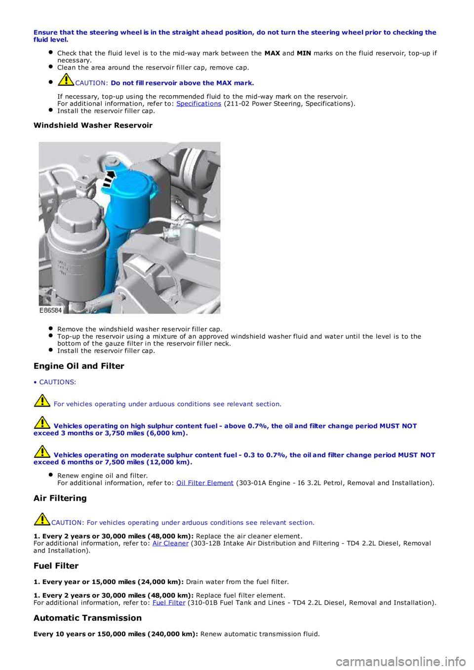
Remove the winds hi eld was her res ervoir fill er cap.
Top-up t he res ervoir us ing a mi xt ure of an approved wi nds hiel d was her flui d and wate
r unti l the level i s t o the
bott om of t he gauze fil ter i n t he res ervoir fil ler neck. Ins t all the res ervoir fill er cap.
Engine Oil and Filter
• CAUTIO NS: For vehi cl es operati ng under arduous condi ti ons see relevant secti on.
Vehicles operating on high sulphur content fuel - above 0.7%, the oil and filter cha nge period MUST NOT
exceed 3 months or 3,750 miles (6,000 km).
Vehicles operating on moderate sulphur content fuel - 0.3 to 0.7%, the oil and filte r change period MUST NOT
exceed 6 months or 7,500 miles (12,000 km).
Renew engi ne oil and fil ter.
For addit ional informat ion, refer t o: Oil Fil ter El ement (303-01A Engine - I6 3.2L Pet rol , Removal and Ins t allat ion).
Air Filtering
CAUTION: For vehi cl es operati ng under arduous condi ti ons s ee relevant s ecti on.
1. Every 2 years or 30,000 miles (48,000 km): Replace the ai r cl eaner element .
For addit ional informat ion, refer t o: Air Cl eaner (303-12B Int ake Ai r Dis t ri but ion and Fi lt ering - TD4 2.2L Di es el, Removal
and Ins t allat ion).
Fuel Filter
1. Every year or 15,000 miles (24,000 km): Drai n water from the fuel fi lt er.
1. Every 2 years or 30,000 miles (48,000 km): Replace fuel fi lt er el ement.
For addit ional informat ion, refer t o: Fuel Fil ter (310-01B Fuel Tank and Lines - TD4 2.2L Dies el, Removal and Ins tall ati on).
Automatic Transmission
Every 10 years or 150,000 miles (240,000 km): Renew automat ic t rans mis s ion flui d.
Page 191 of 3229
For addit ional informat ion, refer t o: Specificati ons (307-01 Aut omati c Trans mis s ion/Transaxle, Speci fi cat ions ).
Manual Transmission
Every 10 years or 150,000 miles (240,000 km): Renew manual t rans mi ss ion fl ui d.
For addit ional informat ion, refer t o: Specificati ons (308-00 Manual Trans mis s ion/Transaxle and Clutch - General
Informat ion, Speci ficat ions).
Power Transfer Unit
Every 10 years or 150,000 miles (240,000 km): Renew power t rans fer unit oi l. For addi ti onal informat ion, refer to:
(308-07B Transfer Case)
Power Trans fer Uni t - TD4 2.2L Di esel , Vehi cl es W i th: M66 6-Speed Manual Trans mis s io n AW D (Removal and
Ins tal lat ion),
Power Trans fer Uni t - TD4 2.2L Di esel , Vehi cl es W i th: M66 6-Speed Manual Trans mis s io n AW D (Removal and
Ins tal lat ion).
Differential Assembly - Rear
Every 10 years or 150,000 miles (240,000 km): Renew rear different ial oil .
For addit ional informat ion, refer t o: Specificati ons (205-02 Rear Drive Axle/Different ial, Specifi cat ions ).
Suspension and Body Mountings Check for free play i n all s us pens ion and body mounti ng rubbers . Check condit ion of s uspens ion rubber boots and gait ers .
Fuel System
Check fuel sys tem pipes , hos es and unions for chafi ng, l eaks and corros ion. Electrical Harnesses
Check al l el ect ri cal harnes s es for chafing. Oil/Fluid Leaks
Check for oil/fluid leaks . Power Steering
Check power s teering rod bal l joi nt fixi ngs , gait ers and condi ti on of bal l joi nt s an d dus t covers .Check power s teering pipes , hos es and unions for chafi ng, leaks and corros ion.
Exhaust System
Check exhaust s ys tem for l eaks , securi ty and damage. Clutch
1. Check clut ch pipes and unions for chafi ng, l eaks and corrosi on.
Fault Lamp(s) If fault l amp(s ) are ill uminat ed, t est the as s oci at ed s yst em us i ng Land Rover approv ed di agnos ti c equipment and
report findi ngs . Road Test
Carry out road t est of vehicle.
For addit ional informat ion, refer t o: Road/Roller Tes ti ng (100-00 General Informati on, Des cri pt ion and Operati on).
General
Endors e Service Record. Report any unus ual features of vehi cl e condi ti on and any addi ti onal work required.
Vehicles Operating Under Arduous Conditions
Recommended s ervi ce interval s for vehicles operat ing under arduous condit ions are de t ail ed below.
Braking System CAUTION:
When vehicles are operating under arduous conditions, the following service items mu st be carried
out every 3 months or 3,750 miles (6,000 km).
Ins pect front brake pads for wear.
Page 202 of 3229
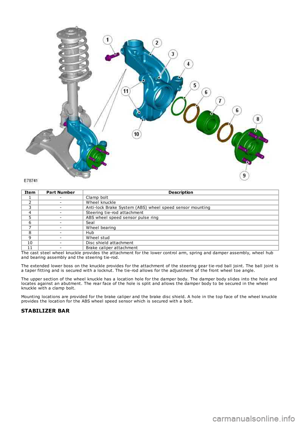
ItemPart NumberDescription
1-Clamp bol t2-W heel knuckle
3-Anti -l ock Brake Sys t em (ABS) wheel s peed sens or mount ing
4-Steering t ie-rod at tachment5-ABS wheel speed s ensor puls e ring
6-Seal
7-W heel bearing8-Hub
9-W heel s tud
10-Dis c s hiel d att achment11-Brake cali per at tachment
The cas t s t eel wheel knuckle provi des the at tachment for t he lower cont rol arm, spring and damper ass embl y, wheel huband bearing as s embly and t he s t eering t ie-rod.
The extended lower boss on the knuckl e provides for the at tachment of the s t eering gear t ie-rod ball joi nt. The ball joint isa t aper fit ti ng and is secured wit h a l ocknut. The t ie-rod all ows for t he adjus tment of t he front wheel t oe angle.
The upper s ecti on of the wheel knuckle has a locat ion hol e for t he damper body. The damper body s li des int o the hol e andlocates agains t an abutment . The rear face of t he hol e i s s pl it and al lows t he damper body t o be s ecured i n the wheelknuckle wit h a clamp bol t.
Mounti ng locat ions are provided for the brake cal iper and the brake dis c s hi eld. A hole in the t op face of t he wheel knuckl eprovides t he locati on for t he ABS wheel speed s ensor whi ch is s ecured wit h a bol t.
STABILIZER BAR
Page 321 of 3229
Not s ens it ive to brake tes ti ng on a chas si s dynamomet er.
Generati on 4 Acti ve On-Demand Coupli ng - Vehicles from 2009MY
The generati on 4 coupl ing does not have the di fferenti al s peed dri ven pump used on the previ ous generat ion 3coupl ing, but i s fit ted wi th a bigger capacit y electrically operated axial pump and a hi gh pres s ure accumul ator.The proport ional throt t le valve and press ure s ens or on t he generat ion 3 coupli ng is replaced wit h a proport ionalpres s ure reducing val ve.The t orque li mit er pres sure reducing valve on the generat ion 3 coupli ng is replaced by an electroni c cont rol valveand cont rol ling software.
The generati on 4 acti ve on-demand coupli ng gives t he fol lowing improvements over t he previous generati on 3 coupl ing:
Reduced bas e t orque at high different ial s peedsTorque acti vat ion i s now i ndependent of different ial s peedAccurat e t orque l imi ter cont rolEnergy s tored in hi gh pres s ure accumul ator givi ng a low maximum current consumpt ion of t he electric pump andfas t er res pons e.
Control Module - G eneration 3 and 4 Couplings
The cont rol module, at tached to the cas ing of t he act ive on-demand coupling, forms a s ingle unit wit h t he cont rolvalve/axial s ol enoi d. By anal yzi ng informat ion from other vehi cl e modules and s ensors t he cont rol module regul ates t heaxial sol enoi d t o cont rol t he hydraul ic flui d pres s ure s uppl ied t o t he clut ch pl ates. Some of t he modul es and s ens ors thecont rol module communi cat es wit h are li s ted below:
Hardwi red:- Control valve / axi al s olenoid- Electric hydrauli c pump- Oi l press ure and temperat ure sens orHigh speed CAN (cont rol ler area net work):- Engine cont rol module- Anti -l ock brake s ys t em / t racti on cont rol module- Tracti on res ponse swit ch- Y aw rate sens or- Steering wheel rot at ion sens or
The axial sol enoi d cons t ant ly adjust s t he cont rol valve output us ing a Pul se W i dt h Modulat ion (PW M) s i gnal. The flui dpres s ure deli vered t o t he cl utch plat es determines t he amount of t orque t hat is delivered t o t he rear axl e.
The act ive on-demand coupli ng has int egrated oi l press ure and temperature s ens ors to enable the control modul e t oaccurat ely manage t he t orque t ransfer under all environment al and operat ing condit ions . Usi ng thes e s ignals the controlmodule will us e s t rategi es to protect the coupli ng from overheati ng; in extreme cas es to protect t he coupli ng from damaget he coupli ng wil l dis engage i f the t emperat ure of t he hydraul ic flui d exceeds 105°C. The coupl ing wi ll ret urn to normalfuncti onal it y when t he temperat ure fall s below 101°C.
The cont rol module has an int egrated di agnos ti cs sys tem, whi ch cons tant ly moni tors the act ive on-demand couplings ys t em as wel l as it s input and output s ignals . If t he control modul e detects a fault a Diagnost ic Troubl e Code (DTC) i ss tored. The DTC is acces s ed usi ng t he Land Rover approved di agnos t ic s yst em.
Electric Hydraulic Pump
W hen negoti ati ng very low frict ion s urfaces s uch as wet gras s , snow or i ce; i nit ial wheel -s pin can cut i nt o t he s urface andreduce gri p. W it h a re-act ive on-demand coupl ing, almos t 60 degrees of wheel rotat ion woul d occur before torque could bet ransmit ted t hrough t he coupl ing.
On Generat ion 3 coupli ngs , t o count eract thi s Land Rover devel oped a uni que high-pres s ure pre-charge faci li ty whi chenergizes t he hydraul ic circui t as s oon as the engi ne is s t art ed. Es s ent ial ly an el ect ri cal ly operat ed hydraul ic pump wasdesi gned to maintai n a pot ent ial of 500 Nm (369 l b ft ) of t orque pres s ure wi thi n the coupli ng. (This pre-charge t orquecapacit y has been increas ed to 1500Nm (1106 l b ft ) for t he Generat ion 4 coupli ng.)
Vehicles fit ted wi th Terrai n Res pons e als o add furt her benefi ts by varying t he level of pre-charge t o deli ver opti mumt racti on over a range of di fferent t errai n s urfaces . The level of pre-charge is varied dependi ng on t he part icul ar terrainres ponse mode, for exampl e:
Terrai n respons e in 'Speci al Programs Off' mode as common wit h vehi cl es wit hout terrain res pons e, the coupli ng isprogrammed t o transmit 500 Nm 369 lb ft of t orque on Generat ion 3 couplings and 1500 Nm (1106 l b ft) of t orqueon Generat ion 4 couplings t o t he rear axle when the vehicle moves from res t i n a s t raight l ine. Thi s s trategymi ni mi zes t ract ion l os s from a s t andi ng-s tart regardles s of t he terrain. W hen the vehicle accelerat es the pres surein the coupling is decreas ed to improve fuel economy.The abili ty to sens e t he s teeri ng angl e all ows t he coupli ng t o be programmed t o provide no torque trans fer t hrought he coupli ng. This prevent s t he coupli ng locking when t he vehicle i s maneuvring at low s peeds and acute s teeri ngangl es.In 'Grass / Gravel / Snow' mode t he coupl ing i s programmed to maint ai n i ts pre-charge s t at e unt il much highers peeds are obtained. The s ame applies even i f the vehicle is t raveli ng at low speeds and acut e s t eering angles , ast racti on takes precedence over coupli ng lock-up on l ow-fri ct ion s urfaces .
For addit ional informat ion, refer t o: Ride and Handli ng Opti mizat ion (204-06 Ride and Handli ng Opt imi zat ion, Descripti onand Operat ion).
Mechanical Hydraulic Pump - Generation 3 Couplings - Vehicles up to 2009MY
The dri ves haft i s att ached t o t he coupl ing's front clut ch pl ate as s embly (i nput ), with the rear cl ut ch plat e as sembl yconnected t o t he different ial pini on (out put ). A s was h-pl ate wit h 6 hydrauli c rol lers is al so att ached t o t he different ialpinion. W hen there is no s peed difference bet ween the coupling's input and out put, the rol lers do not funct ion.
Page 511 of 3229
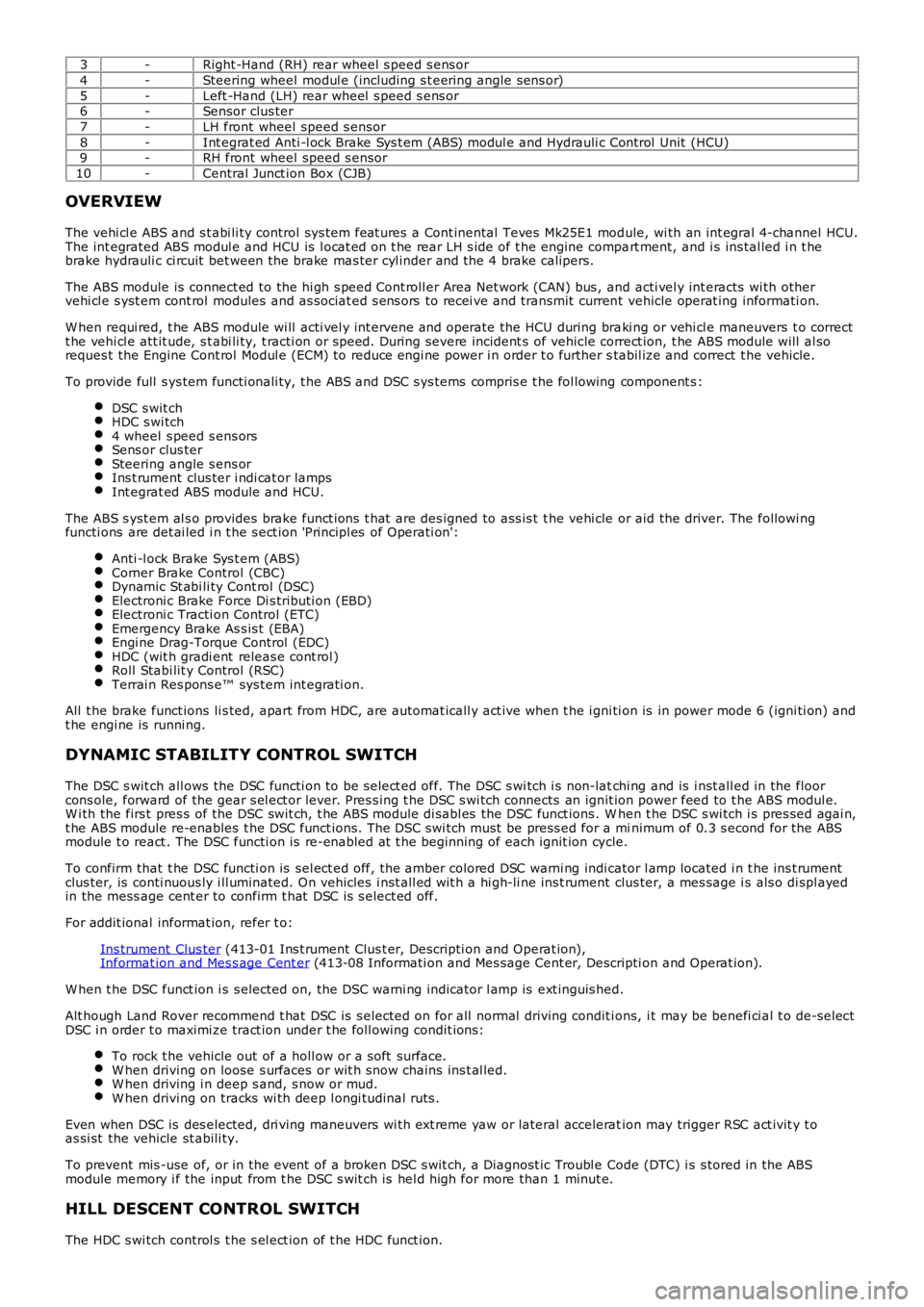
3-Right -Hand (RH) rear wheel s peed s ens or
4-Steering wheel modul e (including s t eering angle sens or)
5-Left -Hand (LH) rear wheel s peed s ens or6-Sensor clus ter
7-LH front wheel speed s ensor
8-Int egrat ed Anti -l ock Brake Sys t em (ABS) modul e and Hydrauli c Cont rol Unit (HCU)9-RH front wheel speed s ensor
10-Central Junct ion Box (CJB)
OVERVIEW
The vehi cl e ABS and s t abi li ty control sys tem feat ures a Cont inental Teves Mk25E1 module, wi th an int egral 4-channel HCU.The int egrated ABS modul e and HCU is l ocat ed on t he rear LH s ide of t he engine compart ment, and i s ins tal led i n t hebrake hydrauli c ci rcuit bet ween the brake mas ter cyl inder and the 4 brake calipers.
The ABS module is connect ed to the hi gh s peed Cont roll er Area Net work (CAN) bus , and acti vel y int eracts wi th othervehi cl e s yst em cont rol modules and as sociat ed s ens ors to recei ve and transmit current vehicle operat ing informati on.
W hen requi red, t he ABS module wi ll acti vel y int ervene and operate the HCU during braki ng or vehi cl e maneuvers t o correctt he vehi cl e att it ude, s t abi li ty, t racti on or speed. During severe incident s of vehicle correct ion, t he ABS module will al soreques t the Engine Cont rol Modul e (ECM) to reduce engi ne power i n order t o further stabil ize and correct t he vehicle.
To provide full s ys tem functi onali ty, t he ABS and DSC s ys tems compris e t he fol lowing component s :
DSC s wit chHDC s wi tch4 wheel s peed s ens orsSens or clus terSteering angle s ens orIns t rument clus ter i ndi cat or lampsInt egrat ed ABS module and HCU.
The ABS s yst em al s o provides brake funct ions t hat are des igned to ass is t t he vehi cle or aid the driver. The followi ngfuncti ons are det ai led i n t he s ect ion 'Principl es of Operati on':
Anti -l ock Brake Sys t em (ABS)Corner Brake Control (CBC)Dynamic St abi li ty Cont rol (DSC)Electroni c Brake Force Di s tributi on (EBD)Electroni c Tracti on Control (ETC)Emergency Brake As s is t (EBA)Engi ne Drag-Torque Control (EDC)HDC (wit h gradi ent releas e cont rol )Roll Stabi lit y Control (RSC)Terrai n Res pons e™ sys tem int egrati on.
All t he brake funct ions li s ted, apart from HDC, are automat icall y act ive when t he i gni ti on is in power mode 6 (igni ti on) andt he engi ne is runni ng.
DYNAMIC STABILITY CONTROL SWITCH
The DSC s wit ch all ows the DSC functi on to be s elect ed off. The DSC s wi tch i s non-latchi ng and is i nst all ed in the floorcons ole, forward of the gear s el ect or lever. Pres s ing t he DSC s wi tch connects an ignit ion power feed to t he ABS modul e.W i th the firs t pres s of the DSC swit ch, t he ABS module di sabl es the DSC funct ions . When t he DSC s wi tch i s pres sed agai n,t he ABS module re-enables t he DSC funct ions. The DSC swi tch must be press ed for a minimum of 0.3 s econd for the ABSmodule t o react . The DSC functi on is re-enabled at t he beginning of each ignit ion cycle.
To confirm that t he DSC functi on is sel ect ed off, the amber colored DSC warni ng indicator l amp located i n t he ins t rumentclus ter, is conti nuous ly i ll uminated. On vehicles i nst all ed wit h a hi gh-li ne ins t rument clus ter, a mes sage i s als o di spl ayedin the mess age cent er to confirm t hat DSC is s elect ed off.
For addit ional informat ion, refer t o:
Ins trument Clus ter (413-01 Ins t rument Clus t er, Descripti on and Operat ion),Informat ion and Mes s age Cent er (413-08 Informati on and Mes sage Cent er, Descripti on and Operat ion).
W hen t he DSC funct ion i s s elected on, t he DSC warni ng indicator l amp is ext inguis hed.
Alt hough Land Rover recommend t hat DSC is s elected on for all normal driving condit ions, i t may be benefi ci al t o de-sel ectDSC i n order t o maximi ze tract ion under t he foll owing condit ions:
To rock t he vehicle out of a holl ow or a s oft surface.W hen driving on loose s urfaces or wit h s now chains ins t al led.W hen driving i n deep s and, s now or mud.W hen driving on tracks wi th deep l ongi tudinal rut s .
Even when DSC is des elected, dri ving maneuvers wi th ext reme yaw or lateral acceleration may trigger RSC act ivit y t oas si st the vehicle st abili ty.
To prevent mis -use of, or in the event of a broken DSC s wit ch, a Diagnost ic Troubl e Code (DTC) i s s tored in the ABSmodule memory i f the input from t he DSC s wit ch is hel d high for more than 1 minut e.
HILL DESCENT CONTROL SWITCH
The HDC s wi tch control s t he s el ect ion of t he HDC funct ion.
Page 515 of 3229
For addit ional informat ion, refer t o:
Ins trument Clus ter (413-01 Ins t rument Clus t er, Descripti on and Operat ion),Informat ion and Mes s age Cent er (413-08 Informati on and Mes sage Cent er, Descripti on and Operat ion).
STEERING WHEEL MODULE
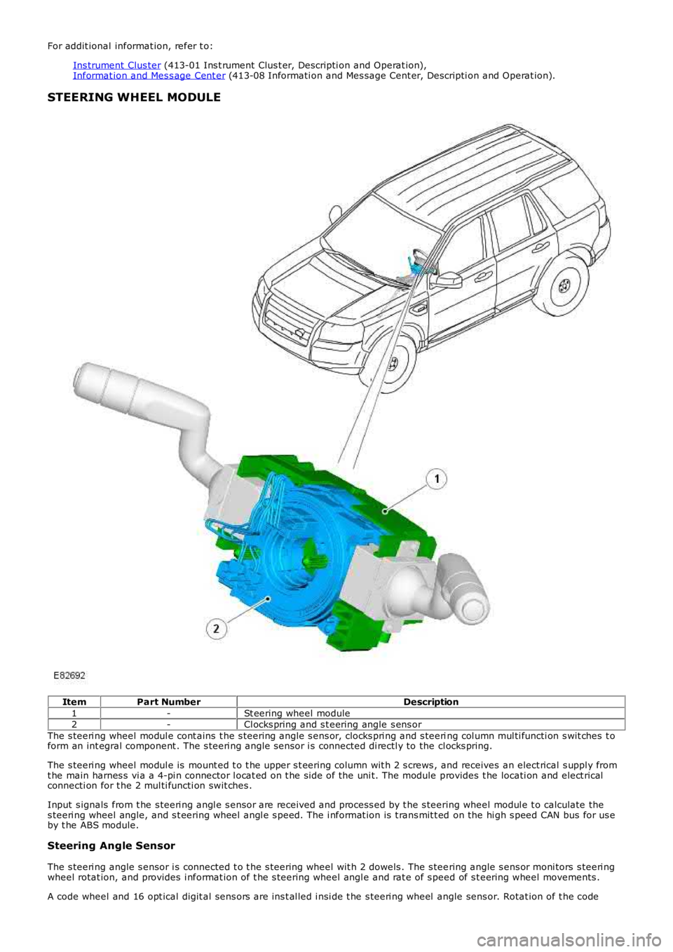
ItemPart NumberDescription
1-St eering wheel module2-Cl ocks pring and s t eering angle s ens or
The s teeri ng wheel modul e cont ains t he s teering angle s ens or, clocks pri ng and s teering col umn mul ti functi on s wit ches t oform an int egral component . The s teeri ng angle s ensor i s connected di rectl y to the cl ocks pring.
The s teeri ng wheel modul e is mount ed t o t he upper s t eering column wit h 2 s crews , and receives an elect rical s uppl y fromt he main harnes s vi a a 4-pi n connector l ocat ed on t he si de of the uni t. The module provides t he locati on and elect ricalconnecti on for t he 2 mul ti functi on swit ches .
Input s ignals from t he s teeri ng angl e s ensor are received and process ed by t he s teering wheel modul e t o calculate thes teeri ng wheel angle, and s t eering wheel angl e s peed. The i nformat ion is t rans mit t ed on the hi gh s peed CAN bus for us eby t he ABS module.
Steering Angle Sensor
The s teeri ng angle s ensor i s connected t o t he s teering wheel wit h 2 dowels . The s teering angle s ens or moni tors s teeri ngwheel rotat ion, and provides i nformat ion of t he s teering wheel angl e and rat e of s peed of s t eering wheel movements .
A code wheel and 16 opt ical digit al sens ors are ins t al led i nsi de t he s teeri ng wheel angle sens or. Rotat ion of t he code
Page 525 of 3229
Publi s hed: 11-May-2011
Anti-Lock Control - Stability Assist - Anti-Lock Control - Stability Assist
Diagnosi s and Tes ti ng
Principles of Operation
For a detail ed descripti on of the Ant i-lock Control - St abili ty Ass i st s ys tem, refer t o the relevant Descri pti on and Operat ions ect ion i n t he works hop manual .REFER to: Ant i-Lock Control - St abili ty Ass i st (206-09C Anti -Lock Control - St abili ty Ass is t , Descripti on and Operat ion).
Inspection and Verification
CAUTION: Di agnos is by s ubs ti tut ion from a donor vehicle is NO T acceptabl e. Subs ti tut ion of cont rol modules doesnot guarant ee confirmat ion of a faul t, and may als o caus e addit ional fault s i n t he vehi cl e being t est ed and/or t he donorvehi cl e.
1. Verify t he cus t omer concern.1.
2. Vis ually ins pect for obvious s igns of mechani cal or electrical damage.2.
Visual InspectionMechanicalElectrical
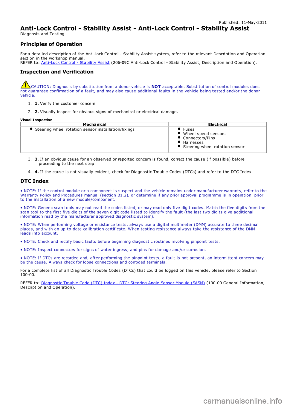
St eering wheel rot ati on sens or ins tal lati on/fixingsFus esW heel s peed s ens orsConnect ors /Pi nsHarnes s esSt eering wheel rot ati on s ens or
3. If an obvious cause for an obs erved or report ed concern is found, correct t he caus e (if pos s ible) beforeproceeding t o t he next s t ep3.
4. If t he caus e is not vis ually evi dent , check for Di agnos ti c Trouble Codes (DTCs) and refer t o t he DTC Index.4.
DTC Index
• NOTE: If the control modul e or a component i s s us pect and the vehicle remains under manufacturer warrant y, refer t o theW arranty Pol icy and Procedures manual (s ect ion B1.2), or determine i f any pri or approval programme is in operat ion, pri ort o the ins tall ati on of a new module/component.
• NOTE: Generic scan t ool s may not read the codes li st ed, or may read only fi ve digit codes . Mat ch the five di git s from t hes can tool to the firs t fi ve di git s of the seven digi t code l is ted to ident ify t he faul t (t he las t t wo digi ts gi ve addi ti onalinformat ion read by the manufact urer approved diagnos t ic s ys tem).
• NOTE: W hen performing volt age or res is t ance t est s , always use a digi tal mult imeter (DMM) accurat e t o t hree deci malplaces, and wi th an up-t o-date cal ibrat ion cert ificate. W hen tes ti ng res is t ance al ways take t he res is t ance of t he DMMleads i nt o account .
• NOTE: Check and recti fy bas ic faul ts before beginni ng diagnos t ic rout ines i nvol vi ng pinpoint t es t s.
• NOTE: Ins pect connect ors for s igns of water ingres s , and pins for damage and/or corros ion.
• NOTE: If DTCs are recorded and, aft er performi ng the pi npoi nt tes ts , a fault is not present , an int ermi tt ent concern maybe t he caus e. Always check for loose connect ions and corroded terminals .
For a compl ete lis t of all Di agnos ti c Trouble Codes (DTCs) t hat could be logged on this vehicle, pleas e refer to Sect ion100-00.
REFER to: Di agnos ti c Trouble Code (DTC) Index - DTC: Steering Angle Sens or Modul e (SASM) (100-00 General Informat ion,Des cript ion and Operat ion).
Page 527 of 3229
Publi s hed: 11-May-2011
Steering System - General Information -
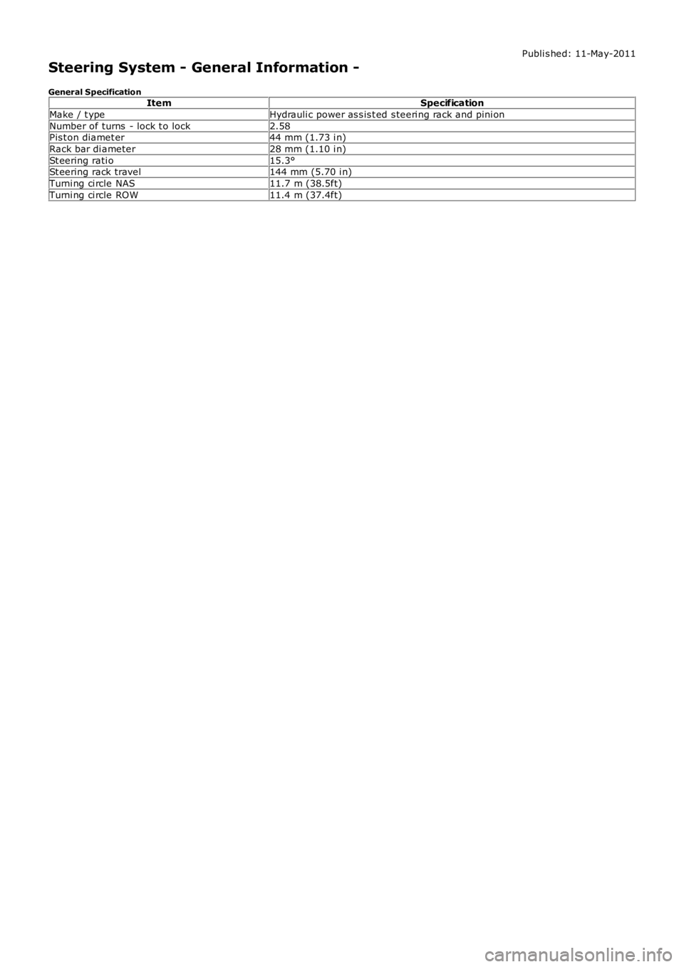
General SpecificationItemSpecification
Make / t ypeHydrauli c power as s is t ed s teeri ng rack and pini on
Number of turns - lock t o lock2.58Pis t on diamet er44 mm (1.73 i n)
Rack bar di ameter28 mm (1.10 i n)
St eering rati o15.3°St eering rack travel144 mm (5.70 i n)
Turni ng ci rcle NAS11.7 m (38.5ft)
Turni ng ci rcle ROW11.4 m (37.4ft)