2006 LAND ROVER FRELANDER 2 reset
[x] Cancel search: resetPage 1777 of 3229
Us ing t hese inputs t he ECM us es an al gorit hm t o moni tor t he driver’s t orque and performance demand in the current geart o est abli sh if t he s ame t orque and performance coul d be achi eved in t he next hi ghest gear to improve fuel effi ci ency,wit hout introduci ng engi ne labori ng.
The s ignal from t he Steeri ng Angle Sens or i s us ed to inhibi t ill uminat ion of t he Gear Shi ft Indi cat or when the vehicle ist ravel ing round a bend in the road.
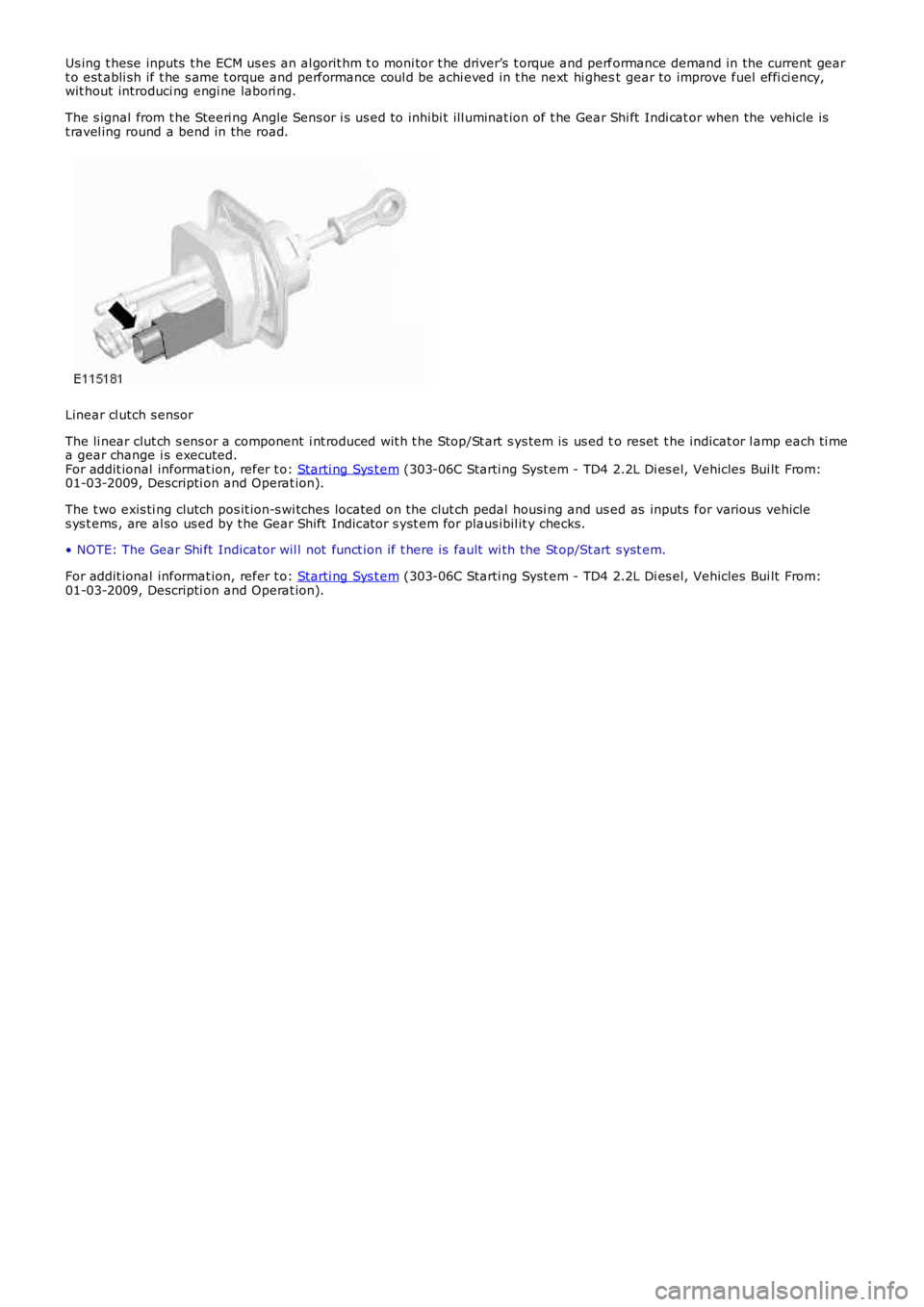
Linear cl utch s ensor
The li near clut ch s ens or a component i nt roduced wit h t he Stop/St art s ys tem is us ed to reset t he indicat or l amp each ti mea gear change i s executed.For addit ional informat ion, refer t o: Starti ng Sys t em (303-06C Starti ng Syst em - TD4 2.2L Di es el, Vehicles Bui lt From:01-03-2009, Descripti on and Operat ion).
The t wo exis ti ng clutch pos it ion-s wi tches located on the clut ch pedal housi ng and used as inputs for various vehicles ys t ems , are al so us ed by t he Gear Shift Indicator s yst em for plaus ibil it y checks.
• NOTE: The Gear Shi ft Indicator wil l not funct ion if t here is fault wi th the St op/St art s yst em.
For addit ional informat ion, refer t o: Starti ng Sys t em (303-06C Starti ng Syst em - TD4 2.2L Di es el, Vehicles Bui lt From:01-03-2009, Descripti on and Operat ion).
Page 1794 of 3229
MessageO ther WarningsReasonAction
Descripti on and Operat ion).
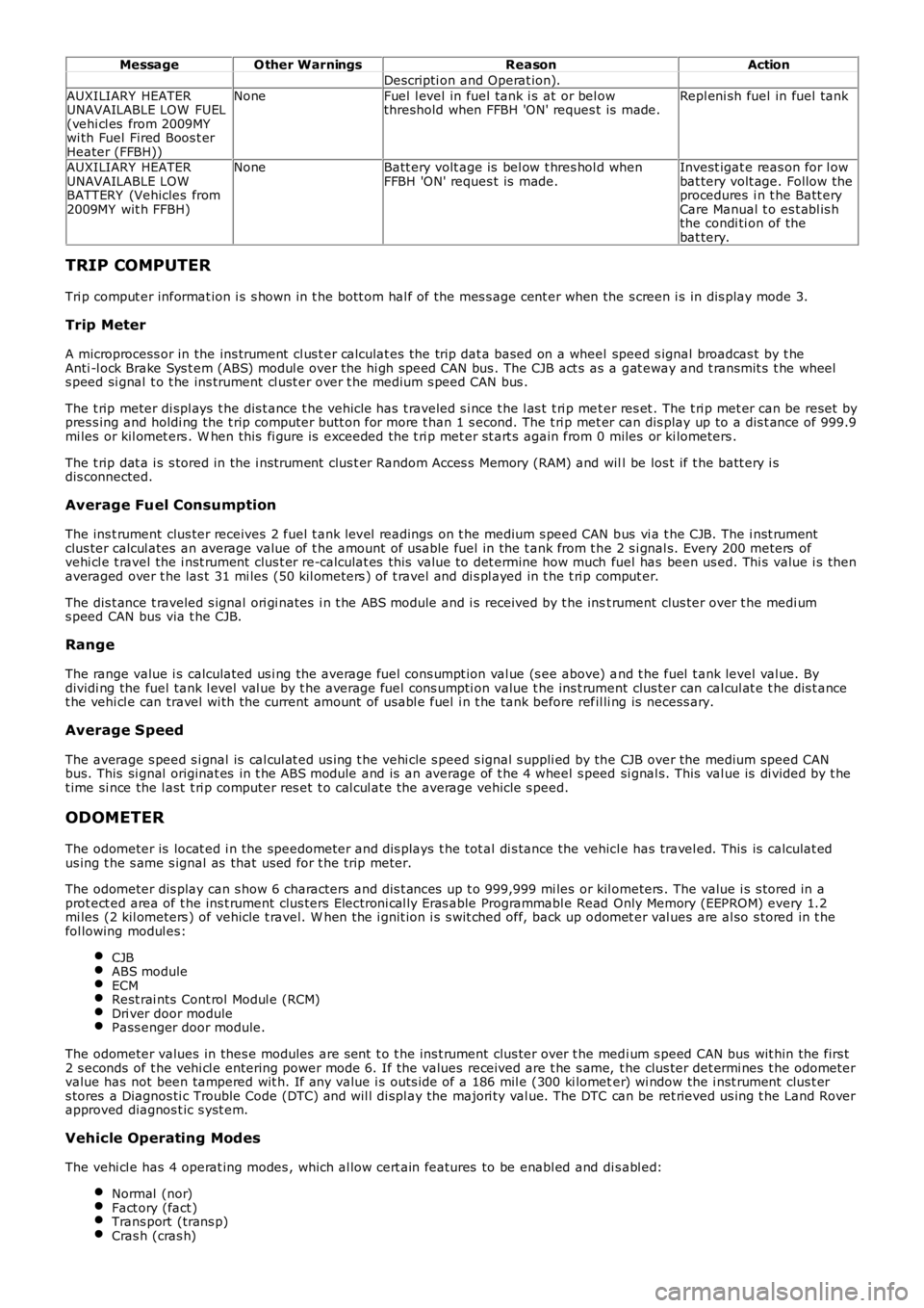
AUXILIARY HEATERUNAVAILABLE LOW FUEL(vehi cl es from 2009MYwi th Fuel Fired Boos t erHeater (FFBH))
NoneFuel l evel in fuel tank i s at or bel owthreshold when FFBH 'ON' reques t is made.Repl eni sh fuel in fuel tank
AUXILIARY HEATERUNAVAILABLE LOWBATTERY (Vehicles from2009MY wit h FFBH)
NoneBatt ery volt age is bel ow t hres hol d whenFFBH 'ON' reques t is made.Invest igat e reas on for l owbat tery volt age. Follow theprocedures i n t he Batt eryCare Manual t o es t abl is hthe condi ti on of thebat tery.
TRIP COMPUTER
Tri p comput er informat ion i s s hown in t he bott om hal f of the mes s age cent er when the s creen i s in dis play mode 3.
Trip Meter
A microprocess or in the ins trument cl us t er calculat es the trip dat a based on a wheel speed s ignal broadcas t by t heAnti -l ock Brake Sys t em (ABS) modul e over the hi gh speed CAN bus . The CJB act s as a gat eway and t ransmit s t he wheels peed si gnal t o t he ins trument cl ust er over t he medium s peed CAN bus .
The t rip meter di spl ays t he dis t ance t he vehicle has t raveled s i nce t he l as t t ri p met er res et . The t ri p met er can be reset bypres s ing and holdi ng the t rip computer butt on for more t han 1 s econd. The t ri p met er can dis play up to a dis t ance of 999.9mi les or kil omet ers . W hen this fi gure is exceeded the t ri p met er st art s again from 0 miles or ki lometers .
The t rip dat a i s s tored in the i nst rument clus t er Random Acces s Memory (RAM) and will be los t if t he batt ery i sdis connected.
Average Fuel Consumption
The ins t rument clus ter receives 2 fuel t ank level readings on t he medium s peed CAN bus vi a t he CJB. The i nst rumentclus ter calcul ates an average value of t he amount of usable fuel in the t ank from t he 2 s i gnal s. Every 200 meters ofvehi cl e t ravel the i nst rument clus t er re-calculat es this val ue to det ermine how much fuel has been us ed. Thi s value i s thenaveraged over t he las t 31 mi les (50 kil ometers ) of t ravel and di s pl ayed in t he t ri p comput er.
The dis t ance t raveled s ignal ori gi nates i n t he ABS module and i s received by t he inst rument clus ter over t he medi ums peed CAN bus via t he CJB.
Range
The range value i s calculated us i ng the average fuel cons umpt ion val ue (s ee above) and t he fuel t ank level val ue. Bydividi ng the fuel tank l evel val ue by t he average fuel cons umpti on value t he ins t rument clus ter can cal cul at e t he dis t ancet he vehi cl e can travel wi th the current amount of us abl e fuel i n t he tank before refil li ng is necess ary.
Average Speed
The average s peed s i gnal is cal cul at ed us ing t he vehi cle s peed s ignal s uppli ed by the CJB over the medium speed CANbus. This si gnal originat es in t he ABS module and is an average of t he 4 wheel s peed si gnal s. This val ue is di vided by t het ime si nce the l ast t ri p computer res et t o cal cul ate the average vehicle s peed.
ODOMETER
The odometer is locat ed i n the speedometer and dis plays t he tot al di s tance the vehicl e has travel ed. This is calculat edus ing t he s ame s ignal as that us ed for t he trip meter.
The odometer dis play can s how 6 characters and dis t ances up t o 999,999 mi les or kil ometers . The value i s s tored in aprot ect ed area of t he ins t rument clus ters Electroni cal ly Eras able Programmabl e Read Only Memory (EEPROM) every 1.2mi les (2 kil ometers ) of vehicle t ravel. W hen the i gnit ion i s s wit ched off, back up odomet er val ues are al so s tored in t hefol lowing modul es:
CJBABS moduleECMRest rai nts Cont rol Modul e (RCM)Dri ver door modulePass enger door module.
The odometer values in thes e modules are s ent t o t he ins t rument clus ter over t he medi um s peed CAN bus wit hin the firs t2 s econds of t he vehi cl e entering power mode 6. If the values received are t he s ame, t he clus ter det ermi nes t he odometervalue has not been tampered wit h. If any value i s outs ide of a 186 mil e (300 ki lometer) wi ndow the i nst rument clus t ers tores a Diagnos ti c Trouble Code (DTC) and wil l di spl ay the majori ty val ue. The DTC can be ret rieved us ing t he Land Roverapproved diagnos t ic s yst em.
Vehicle Operating Modes
The vehi cl e has 4 operat ing modes , which al low cert ain features to be enabl ed and dis abl ed:
Normal (nor)Fact ory (fact )Trans port (trans p)Cras h (cras h)
Page 1795 of 3229
The current vehicle operat ing mode, s hown in parenthes is above, i s dis played in the odomet er for 5 s econds when t hevehi cl e first ent ers power mode 6.
• NOTE: 'Nor' is only di s pl ayed in t he Odometer when t he vehicle operat ing mode is changed t o normal from any of theother vehi cle operat ing modes . Under al l ot her condit ions , 'Nor' is not di spl ayed.
The vehi cl e operat ing mode can be changed us i ng the Land Rover approved di agnos ti c sys t em.
Gear Position
The gear pos it ion i ndicat or s hows the current aut omati c t ransmis s ion s elector l ever posi ti on. During normal operat ion thedis play wi ll s how P (park), R (revers e), N (neutral) and D (drive). W hen the t rans mis s ion is operat ed in 'CommandShi ft ™'mode, the odomet er di spl ays the current ly sel ect ed manual gear; 1, 2, 3, 4, 5 or 6.
In the event of eit her a CAN bus fai lure, or if t he TCM det ect s a t rans mi ss i on overheat s it uati on, t he odometer wi ll dis playt he let ter 'E' in the s ame area of t he dis play as t he 'CommandShift™' s elected gear informat ion.
Supplemental Restrain System Warning Indicator
If the i nst rument clus ter det ect s the Supplement al Res t raint Sys tem (SRS) warni ng indicator has fai led, t he mes sage 'SrS'wil l be dis played in the odomet er and a DTC s tored. The DTC can be ret rieved from the ins trument cl us t er us i ng the LandRover approved diagnost ic sys tem.
Service Interval Indicator
The Service Interval Indi cat or (SII) i nforms t he driver when t he next vehicle servi ce is due. The ins t rument clus ter monit orst he dis tance t he vehi cl e has travel ed and t he ti me el aps ed s ince t he las t s ervice.
If vehicle dis tance is the t rigger for the SII, 'SERVICE' will be di s pl ayed in t he odometer accompanied by a dis tancequal ifier (ei ther 'MILES' or 'KM' dependi ng on t he ins trument cl ust er s pecificati on). A di st ance counter wi ll als o be di s pl ayedin the t op Ri ght Hand (RH) corner of t he odometer. If t he point at which a servi ce is requi red is pas sed, t he count er wi lldis play a negat ive value. W hen acti vat ed, t he SII is di spl ayed for 5 s econds when t he vehi cl e enters power mode 6.
If ti me i s the trigger for the SII, 'SERVICE' wil l be di s pl ayed in t he odometer accompanied by a clock symbol . A count er willals o be di spl ayed i n t he t op RH corner of the odomet er. If t he point at which a s ervice is required is pas s ed, t he count erwil l dis play a negati ve val ue. Agai n, when act ivated t he SII is dis played for 5 s econds when t he vehi cl e enters power mode6.
If bot h t he dis tance and t ime triggers are acti vat ed, t he SII wil l di s pl ay the di s tance informat ion for 5 s econds, foll owedby t he ti me i nformati on for 5 s econds .
W hen a service has been carri ed out , t he SII wi ll need t o be re-s et. This can be done us ing t he Land Rover approveddiagnost ic s ys tem or foll owing a manual re-s et procedure. The manual re-s et mode is ent ered by carrying out the foll owingrout ine:
Pres s and hold the t ri p res et butt on wi th the vehicle st ati onary and in a power mode les s t han 6.W hi le holdi ng the trip res et but ton, enter t he vehi cl e int o power mode 6.Releas e the trip res et but ton wit hi n 10 s econds of entering power mode 6.
If the manual re-set mode has been s ucces s full y entered 'dISt ' or 'DATE' wi ll be di spl ayed i n t he odomet er, dependi ng onwhich t ri gger has been acti vat ed.
To clear the 'dISt ' trigger pres s, and hold the t rip reset but ton for more than 5 s econds wit hi n 10 s econds of entering t hemanual re-s et mode. If s ucces s ful, 'RESET' wil l be dis played in the odometer for 5 seconds. If t he dat e t ri gger has notbeen act ivated 'END' wil l t hen be dis played i n t he odomet er.
• NOTE: The dis t ance t ri gger wi ll not res et if t he dis t ance t he vehi cle has t raveled i s les s t han 20% of t he next s ervi ceint erval val ue.
If the dat e trigger has been act ivated, 'DATE' wil l be dis played in t he odometer. To clear the t ri gger, pres s and hold t het rip res et but t on for more t han 5 s econds wit hin 10 s econds of 'DATE' being di s pl ayed. If succes s ful , 'RESET' wi ll bedis played wit hin the odomet er for 5 s econds fol lowed by 'END'. The odomet er wil l now exit re-s et mode.
AMBIENT AIR TEMPERATURE
The ins t rument clus ter can dis play t he ambient air t emperature readi ng in ei ther degrees Cels ius or Fahrenhei t. Theambient air t emperat ure s ignal ori gi nat es i n the ambient air t emperature s ens or. The s ens or i s a Negati ve TemperatureCoefficient (NTC) t hermi st or, and i s mounted i n t he LH door mirror. A t emperature value i s cal cul ated by t he ECM andbroadcas t over the hi gh speed CAN bus to t he i ns t rument clus ter.
If the t emperat ure value fall s bel ow 4ºC (39ºF) t he mes sage center wi ll flas h the low ambi ent ai r temperat ure icon 5t imes . Thi s i s accompanied by a chime from the i nst rument clus t er s ounder. The low ambient air t emperature icon wi ll berepeated if t he ambient air t emperature ri s es above 6ºC (43ºF) t hen drops below 4ºC (39ºF) again or a new ignit ion cycleis st art ed.
Page 1819 of 3229
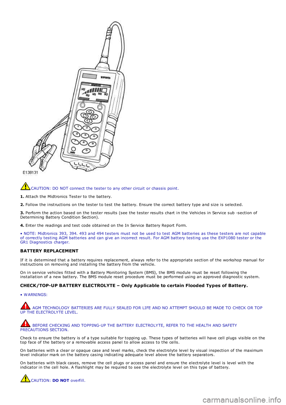
CAUTION: DO NOT connect the tes ter t o any other circui t or chas si s point .
1. Att ach the Midtronics Test er to the bat tery.
2. Fol low the i nst ruct ions on t he tes t er t o t est the bat tery. Ens ure t he correct batt ery type and s ize i s s elect ed.
3. Perform the acti on based on the t es ter res ult s (s ee the t es ter res ult s chart i n the Vehi cl es in Servi ce s ub -s ecti on ofDetermini ng Batt ery Condit ion Secti on).
4. Ent er the readings and t es t code obtained on the In Servi ce Bat tery Report Form.
• NOTE: Mi dt roni cs 393, 394. 493 and 494 t es ters mus t not be us ed t o t est AGM batt eri es as thes e t est ers are not capableof correctl y t es t ing AGM batt eries and can gi ve an incorrect resul t. For AGM batt ery tes ti ng us e the EXP1080 t es t er or t heGR1 Di agnos ti cs charger.
BATTERY REPLACEMENT
If it is det ermined t hat a bat tery requires repl acement, al ways refer t o t he appropri at e s ecti on of the works hop manual forins t ructi ons on removing and i nst all ing t he batt ery from t he vehi cl e.
On i n s ervice vehicles fit ted wit h a Bat tery Monit oring Sys tem (BMS), t he BMS module must be res et foll owing t heins t al lat ion of a new bat tery. The BMS module reset procedure must be performed us ing an approved diagnost ic sys tem.
CHECK/TOP-UP BATTERY ELECTROLYTE – Only Applicable to certain Flooded Typ es of Battery.
• W ARNINGS:
AGM TECHNOLOGY BATTERIES ARE FULLY SEALED FOR LIFE AND NO ATTEMPT SHOULD BE MADE TO CHECK OR TOPUP THE ELECTROLY TE LEVEL.
BEFORE CHECKING AND TOPPING-UP THE BATTERY ELECTROLY TE, REFER TO THE HEALTH AND SAFETYPRECAUTIONS SECTION.
Check t o ens ure t he batt ery is of a t ype s uit abl e for t oppi ng up. Thes e t ypes of batteri es wil l have cell pl ugs vi si ble on thet op face of the bat tery or a removable acces s panel t o all ow acces s t o t he cel ls .
On bat teries wi th a cl ear or opaque cas e and l evel marks, check the el ect rolyt e level by vis ual i nspecti on of the maxi mumlevel indicator mark on t he batt ery cas ing i ndi cat ing adequat e l evel above the bat tery separat ors .
On bat teries wi th bl ack cas es, remove the cell pl ugs or acces s panel and ens ure the el ect rol yt e l evel is level wi th theindicat or i n t he cel l hol e. A flas hl ight may be requi red to s ee t he electrolyt e level on thi s type of batt ery.
CAUTION: DO NOT overfil l.
Page 1827 of 3229
Publi s hed: 11-May-2011
Battery, Mounting and Cables -
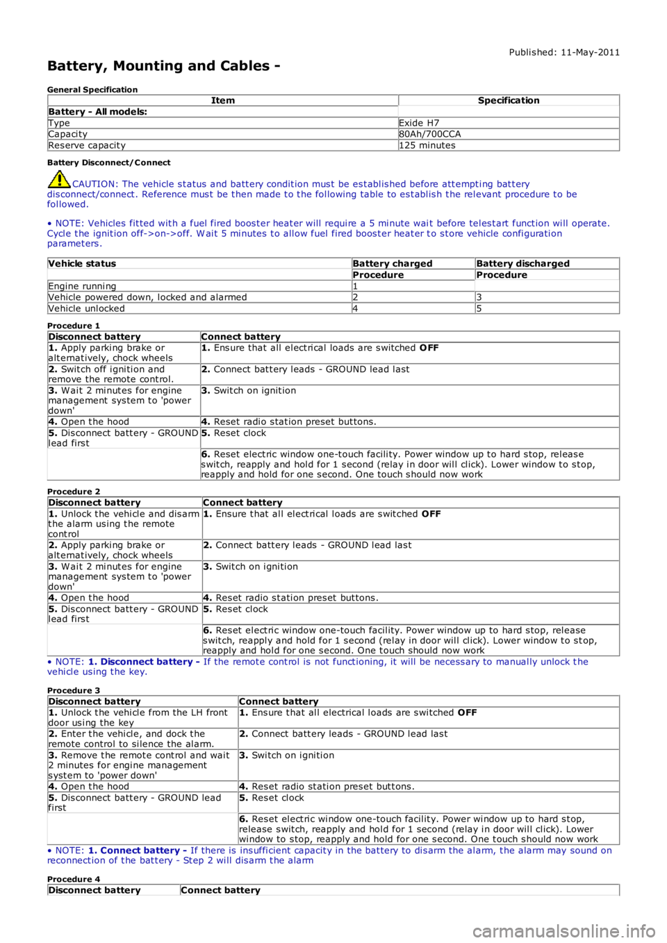
General SpecificationItemSpecification
Battery - All models:
TypeExide H7Capaci ty80Ah/700CCA
Res erve capacit y125 minutes
Battery Disconnect/C onnect
CAUTION: The vehicle s t atus and batt ery condit ion mus t be es t abl is hed before att empti ng bat t erydis connect/connect . Reference mus t be t hen made t o t he fol lowing table to es t abl is h t he rel evant procedure t o befol lowed.
• NOTE: Vehicles fit ted wit h a fuel fired boos t er heat er will requi re a 5 mi nute wait before tel es t art funct ion wi ll operate.Cycl e t he ignit ion off->on->off. W ai t 5 mi nutes t o all ow fuel fired boos t er heat er to s t ore vehicle confi gurati onparamet ers .
Vehicle statusBattery chargedBattery discharged
ProcedureProcedure
Engine runni ng1Vehicle powered down, l ocked and alarmed23
Vehicle unl ocked45
Procedure 1
Disconnect batteryConnect battery1. Apply parki ng brake oralt ernat ively, chock wheels1. Ens ure that all el ect ri cal loads are s wit ched O FF
2. Swit ch off i gni ti on andremove the remote cont rol.2. Connect bat t ery l eads - GROUND lead l ast
3. W ai t 2 mi nut es for enginemanagement sys tem t o 'powerdown'
3. Swit ch on ignit ion
4. Open t he hood4. Reset radi o s tat ion preset but tons .
5. Dis connect batt ery - GROUNDl ead firs t5. Reset clock
6. Reset elect ric window one-t ouch facili ty. Power window up t o hard s top, rel eas es wit ch, reapply and hol d for 1 s econd (relay i n door wil l cl ick). Lower window t o s top,reapply and hold for one s econd. One t ouch s hould now work
Procedure 2
Disconnect batteryConnect battery
1. Unlock t he vehi cl e and dis armt he alarm us ing t he remotecont rol
1. Ensure t hat al l el ect ri cal l oads are s wit ched OFF
2. Apply parki ng brake oralt ernat ively, chock wheels2. Connect batt ery l eads - GROUND l ead las t
3. W ai t 2 mi nut es for enginemanagement sys tem t o 'powerdown'
3. Swit ch on i gni ti on
4. Open t he hood4. Res et radio s t ati on pres et but tons .
5. Dis connect batt ery - GROUNDl ead firs t5. Res et cl ock
6. Res et el ect ri c window one-touch facil it y. Power window up to hard s top, rel eases wit ch, reappl y and hold for 1 s econd (rel ay in door wil l cl ick). Lower window t o s top,reapply and hol d for one s econd. One t ouch should now work
• NOTE: 1. Disconnect battery - If the remot e cont rol is not funct ioning, it will be necess ary to manual ly unlock thevehi cl e us ing t he key.
Procedure 3
Disconnect batteryConnect battery1. Unlock t he vehi cl e from the LH frontdoor us i ng the key1. Ens ure t hat al l electrical l oads are s wi tched OFF
2. Enter t he vehi cl e, and dock t heremote control to si lence the al arm.2. Connect batt ery leads - GROUND l ead las t
3. Remove t he remot e cont rol and wai t2 minutes for engi ne managements yst em to 'power down'
3. Swi tch on i gni ti on
4. Open t he hood4. Res et radio st ati on pres et but t ons .
5. Dis connect batt ery - GROUND leadfirst5. Res et cl ock
6. Res et el ect ri c wi ndow one-touch facil it y. Power wi ndow up to hard s t op,release s wit ch, reapply and hol d for 1 second (relay i n door wil l cl ick). Lowerwi ndow to s top, reapply and hold for one s econd. One t ouch s hould now work
• NOTE: 1. Connect battery - If there is ins uffi cient capacit y in the bat tery to di s arm the al arm, t he alarm may sound onreconnect ion of t he bat t ery - St ep 2 wi ll dis arm t he alarm
Procedure 4
Disconnect batteryConnect battery
Page 2179 of 3229
and adopt ed as t he current pos it ions. This wil l al low the relat ive memory posi ti ons to be ret ained wit hout any need t o
recali brate the power s eat modul e.
The power seat module is able to be 'flas hed' for s ervice updates or i nterrogat ed us ing t he Land Rover approved diagnost ic
equi pment.
Up t o 3 di fferent s eat pos it ions are abl e t o be s t ored i n the power s eat modul e. Sea t pos it ions are st ored in memory by
pres s ing t he memory butt on ( M), and t hen 1 of t he 3 memory s tore butt ons ( 1, 2, 3) wi thi n 5 s econds . The memory
butt ons are l ocat ed on t he s wit ch pack. The swit ch pack memory butt ons allow the dri ver t o cont rol t he memory st orage
and recall operat ions for t he s eat and ext erior mi rrors . The s wit ch pack but tons are non-lat chi ng, moment ary act ion
s wit ches .
On vehicles i nst all ed wit h a hi gh-li ne ins t rument clus ter and t he ignit ion s wi tched on, the s eat posi ti on memory s tore
commands are di spl ayed i n t he mes sage center and a si ngl e chime is s ounded to confi r m t he new s eat pos it ion i s s aved.
• NOTE: Low-l ine i nst rument clus ters are not i nst all ed to vehi cl es equi pped wit h a m emory s eat sys t em.
For addit ional informat ion, refer t o: Ins t rument Clus ter (413-01 Inst rument Cl us t er, Des cript ion and Operat ion) /
Informat ion and Mes s age Cent er (413-08 Informat ion and Mes s age Cent er, Des cript ion and Operat ion).
The power seat module provi des the foll owing driver sel ect abl e functi ons: Seat and ext erior mirror memory recall Immediat e s eat adjus t ment.
For furt her operat ing det ail s of the driver sel ect abl e funct ions, refer t o t he s ect i
on 'Principles of Operat ion'.
The act ivi ty of t he s eat is automat icall y monit ored by t he power s eat module. The mo dule wil l react to motors that are not
functi oni ng correct ly t o an operat ion reques t , and will al so aim to reduce power con sumpt ion during peri ods of i nact ivit y.
The power seat module provi des the foll owing automat ic moni toring funct ions : Stal l det ect ion mode Sleep mode
Batt ery moni tor mode.
For furt her operat ing det ail s of the aut omati c monit oring funct ions , refer t o t he s e
ct ion 'Pri nci pl es of Operati on'.
Calibration of Power Seat Module
If the power s eat modul e is replaced in servi ce, t he repl acement module must be cali brat ed usi ng t he Land Rover approved
diagnost ic equipment . The cal ibrat ion routi ne is necess ary for t he power s eat module t o reset t he s eat dat um values .
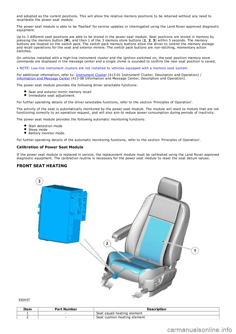
FRONT SEAT HEATING Item
Part Number Description
1 -Seat s quab heat ing el ement
2 -Seat cus hi on heat ing el ement
Page 2314 of 3229
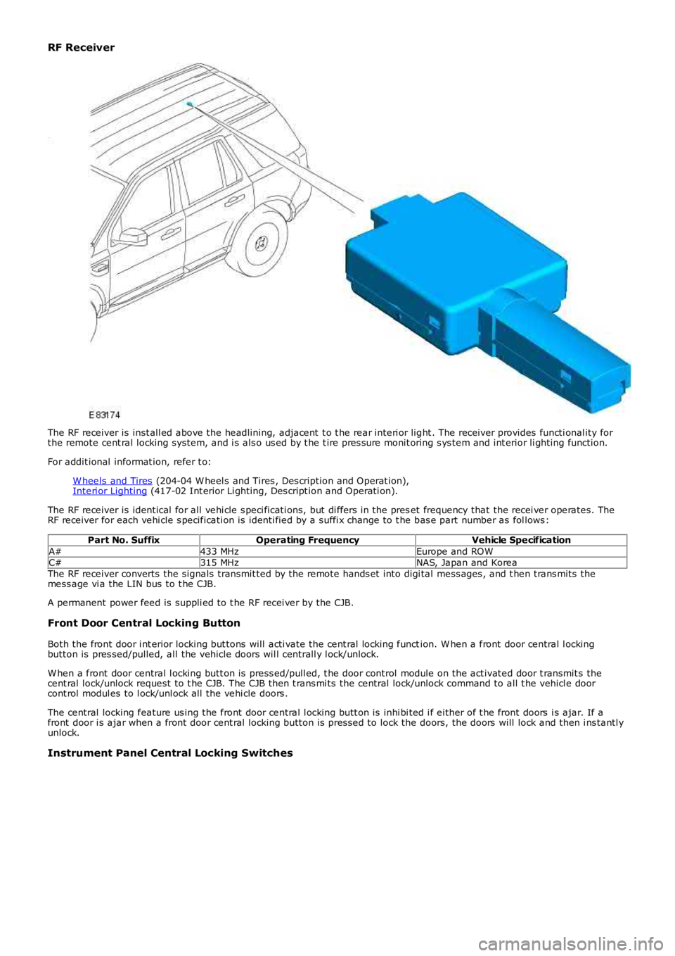
RF Receiver
The RF receiver is inst all ed above the headlining, adjacent t o t he rear interi or light . The receiver provides functi onal ity forthe remote cent ral locking system, and i s als o us ed by t he t ire pres sure monit oring s ys tem and int erior li ghting function.
For addit ional informat ion, refer t o:
W heels and Tires (204-04 W heel s and Tires , Des cription and Operat ion),Interi or Lighting (417-02 Int erior Li ghting, Des cript ion and Operati on).
The RF receiver is identical for all vehi cle s peci ficati ons, but di ffers in the preset frequency that the recei ver operates. TheRF receiver for each vehi cle s pecificati on is identi fied by a suffi x change to t he bas e part number as fol lows :
Part No. SuffixOperating FrequencyVehicle Specification
A#433 MHzEurope and ROWC#315 MHzNAS, Japan and KoreaThe RF receiver converts the signals transmit ted by the remote hands et into digi tal mess ages , and t hen trans mits themess age vi a the LIN bus to t he CJB.
A permanent power feed is suppli ed to t he RF recei ver by the CJB.
Front Door Central Locking Button
Both the front door i nt erior locking but tons will acti vate the cent ral locking function. W hen a front door central l ockingbutton is pres sed/pulled, all the vehicle doors wil l centrall y l ock/unlock.
W hen a front door central l ocking butt on is press ed/pull ed, t he door control module on the act ivated door t ransmit s thecent ral lock/unlock request to t he CJB. The CJB then t rans mi ts the central lock/unlock command to all t he vehicl e doorcont rol modul es to l ock/unl ock all the vehi cle doors .
The central locking feature us ing the front door central l ocking butt on is inhi bi ted i f either of t he front doors i s ajar. If afront door i s ajar when a front door cent ral locking button is pres sed to lock the doors, the doors will lock and then i ns tantl yunlock.
Instrument Panel Central Locking Switches
Page 2373 of 3229
1
1
1
1
1
1
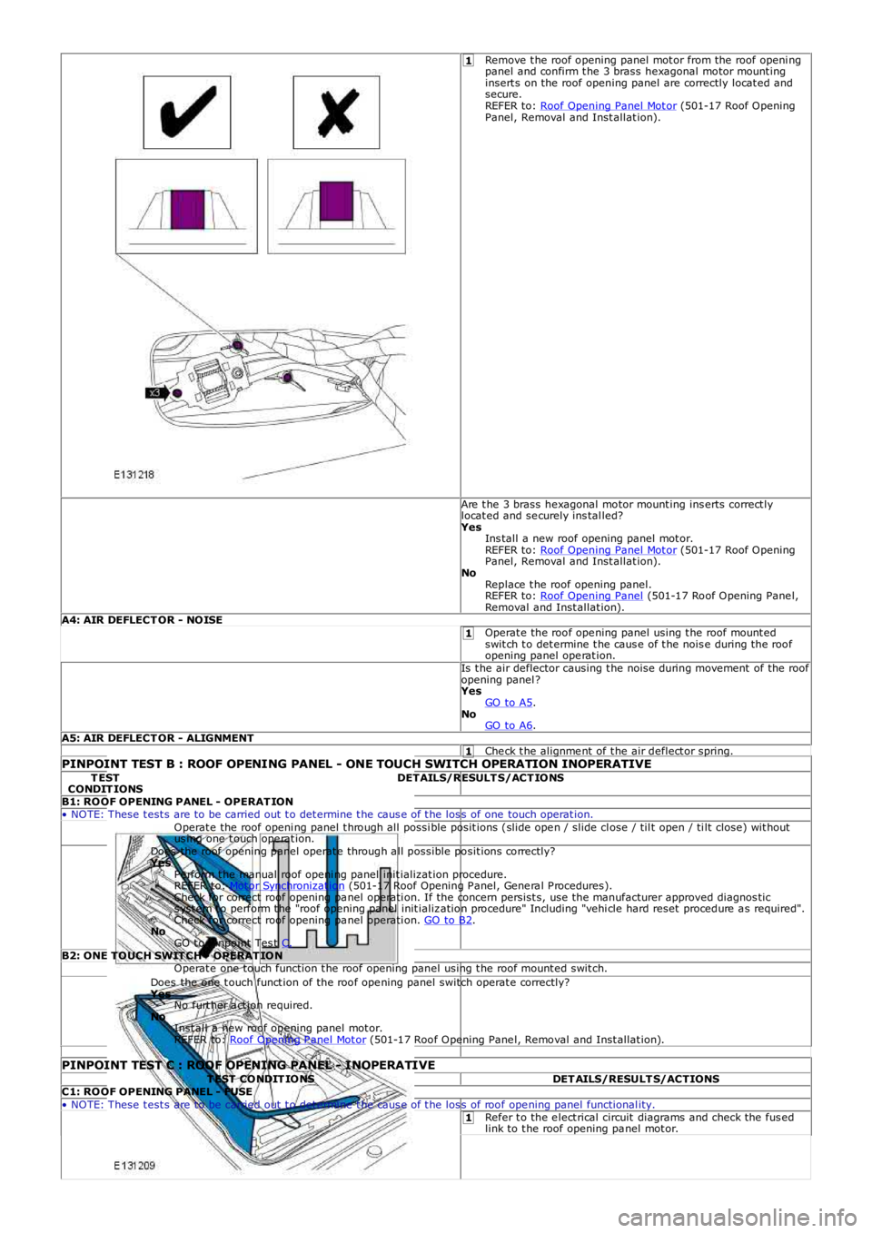
Remove t he roof opening panel mot or from the roof openi ngpanel and confirm t he 3 brass hexagonal motor mount inginsert s on the roof opening panel are correctly locat ed andsecure.REFER to: Roof Opening Panel Mot or (501-17 Roof OpeningPanel, Removal and Inst allat ion).
Are t he 3 brass hexagonal motor mount ing ins erts correct lylocat ed and se curely ins tal led?YesIns tall a new roof opening panel mot or.REFER to: Roof Opening Panel Mot or (501-17 Roof OpeningPanel, Removal and Inst allat ion).NoReplace t he roof opening panel.REFER to: Roof Opening Panel (501-17 Roof Opening Pane l,Removal and Inst allat ion).A4: AIR DEFLECT OR - NOISEOperat e the roof ope ning panel using t he roof mount edswit ch t o det ermine t he caus e of t he nois e during the roofopening panel ope rat ion.Is t he air deflector causing t he noise during movement of the roofopening panel ?YesGO to A5.NoGO to A6.A5: AIR DEFLECT OR - ALIGNMENTChe ck t he alignme nt of t he air deflect or spring.PINPOINT TEST B : ROOF OPENING PANEL - ONE TOUCH SWITCH OPERATION INOPERATIVET ESTCONDIT IONSDETAILS/RESULT S/ACT IONS
B1: ROOF OPENING PANEL - OPERAT ION• NOTE: These t est s are to be carried out t o det ermine t he caus e of t he los s of one touch operat ion.Operat e the roof openi ng panel t hrough all possi ble posit ions (slide ope n / slide close / til t open / ti lt close) wit houtus ing one t ouch ope rat ion.Does the roof opening panel operat e through a ll possible posit ions correctly?YesPe rform t he manual roof openi ng panel init ializat ion procedure.REFER to: Mot or Synchronizat ion (501-17 Roof Opening P anel, Gene ra l P rocedures).Check for correct roof opening pa nel operati on. If the concern persist s, use t he manufacturer approved diagnos tics yst em t o perform t he "roof opening panel init ializ ation procedure" Including "vehi cle hard reset procedure a s required".Check for correct roof opening pa nel operati on. GO to B2.NoGO t o Pinpoint Tes t C.B2: ONE TOUCH SWIT CH - OPERAT IONOperat e one touch function t he roof opening panel using t he roof mount ed swit ch.Does the one t ouch funct ion of the roof ope ning panel switch operat e correctly?YesNo furt her a ct ion required.NoInst all a new roof opening panel mot or.REFER to: Roof Opening P anel Mot or (501-17 Roof Opening Pane l, Removal and Inst allat ion).
PINPOINT TEST C : ROOF OPENING PANEL - INOPERATIVET EST CONDIT IONSDET AILS/RESULT S/ACTIONSC1: ROOF OPENING PANEL - FUSE• NOTE: These t est s are to be carried out t o det ermine t he caus e of t he los s of roof ope ning panel functional ity.Refer t o the e lect rical circuit diagrams and check the fus edlink to t he roof opening pa nel mot or.