2006 LAND ROVER FRELANDER 2 radio
[x] Cancel search: radioPage 1827 of 3229
Publi s hed: 11-May-2011
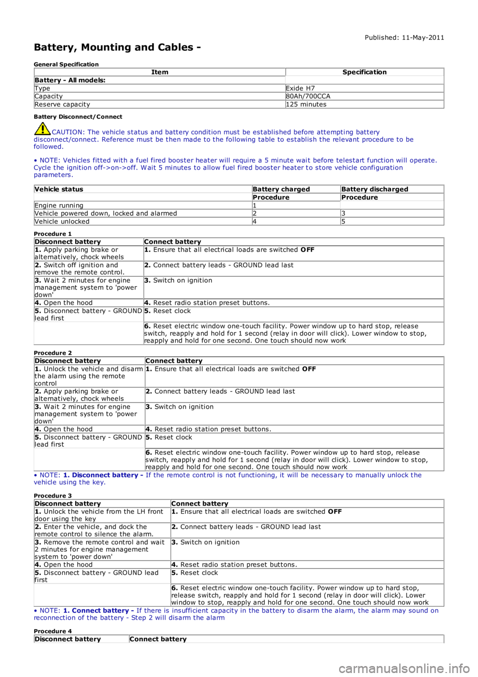
Battery, Mounting and Cables -
General SpecificationItemSpecification
Battery - All models:
TypeExide H7Capaci ty80Ah/700CCA
Res erve capacit y125 minutes
Battery Disconnect/C onnect
CAUTION: The vehicle s t atus and batt ery condit ion mus t be es t abl is hed before att empti ng bat t erydis connect/connect . Reference mus t be t hen made t o t he fol lowing table to es t abl is h t he rel evant procedure t o befol lowed.
• NOTE: Vehicles fit ted wit h a fuel fired boos t er heat er will requi re a 5 mi nute wait before tel es t art funct ion wi ll operate.Cycl e t he ignit ion off->on->off. W ai t 5 mi nutes t o all ow fuel fired boos t er heat er to s t ore vehicle confi gurati onparamet ers .
Vehicle statusBattery chargedBattery discharged
ProcedureProcedure
Engine runni ng1Vehicle powered down, l ocked and alarmed23
Vehicle unl ocked45
Procedure 1
Disconnect batteryConnect battery1. Apply parki ng brake oralt ernat ively, chock wheels1. Ens ure that all el ect ri cal loads are s wit ched O FF
2. Swit ch off i gni ti on andremove the remote cont rol.2. Connect bat t ery l eads - GROUND lead l ast
3. W ai t 2 mi nut es for enginemanagement sys tem t o 'powerdown'
3. Swit ch on ignit ion
4. Open t he hood4. Reset radi o s tat ion preset but tons .
5. Dis connect batt ery - GROUNDl ead firs t5. Reset clock
6. Reset elect ric window one-t ouch facili ty. Power window up t o hard s top, rel eas es wit ch, reapply and hol d for 1 s econd (relay i n door wil l cl ick). Lower window t o s top,reapply and hold for one s econd. One t ouch s hould now work
Procedure 2
Disconnect batteryConnect battery
1. Unlock t he vehi cl e and dis armt he alarm us ing t he remotecont rol
1. Ensure t hat al l el ect ri cal l oads are s wit ched OFF
2. Apply parki ng brake oralt ernat ively, chock wheels2. Connect batt ery l eads - GROUND l ead las t
3. W ai t 2 mi nut es for enginemanagement sys tem t o 'powerdown'
3. Swit ch on i gni ti on
4. Open t he hood4. Res et radio s t ati on pres et but tons .
5. Dis connect batt ery - GROUNDl ead firs t5. Res et cl ock
6. Res et el ect ri c window one-touch facil it y. Power window up to hard s top, rel eases wit ch, reappl y and hold for 1 s econd (rel ay in door wil l cl ick). Lower window t o s top,reapply and hol d for one s econd. One t ouch should now work
• NOTE: 1. Disconnect battery - If the remot e cont rol is not funct ioning, it will be necess ary to manual ly unlock thevehi cl e us ing t he key.
Procedure 3
Disconnect batteryConnect battery1. Unlock t he vehi cl e from the LH frontdoor us i ng the key1. Ens ure t hat al l electrical l oads are s wi tched OFF
2. Enter t he vehi cl e, and dock t heremote control to si lence the al arm.2. Connect batt ery leads - GROUND l ead las t
3. Remove t he remot e cont rol and wai t2 minutes for engi ne managements yst em to 'power down'
3. Swi tch on i gni ti on
4. Open t he hood4. Res et radio st ati on pres et but t ons .
5. Dis connect batt ery - GROUND leadfirst5. Res et cl ock
6. Res et el ect ri c wi ndow one-touch facil it y. Power wi ndow up to hard s t op,release s wit ch, reapply and hol d for 1 second (relay i n door wil l cl ick). Lowerwi ndow to s top, reapply and hold for one s econd. One t ouch s hould now work
• NOTE: 1. Connect battery - If there is ins uffi cient capacit y in the bat tery to di s arm the al arm, t he alarm may sound onreconnect ion of t he bat t ery - St ep 2 wi ll dis arm t he alarm
Procedure 4
Disconnect batteryConnect battery
Page 1828 of 3229
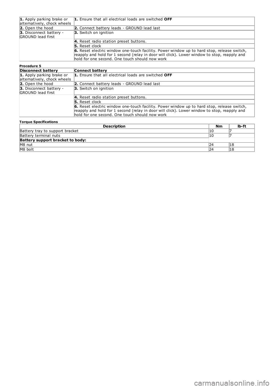
1. Apply parki ng brake oralt ernat ively, chock wheels1. Ens ure t hat al l elect rical l oads are s wit ched OFF
2. Open t he hood2. Connect batt ery leads - GROUND l ead las t3. Dis connect batt ery -GROUND lead firs t3. Swit ch on i gni ti on
4. Res et radio s t ati on pres et but tons .
5. Res et cl ock
6. Res et el ect ri c window one-touch facil it y. Power wi ndow up to hard s t op, release swit ch,reapply and hol d for 1 s econd (relay i n door wil l cl ick). Lower window t o s top, reapply andhold for one s econd. One t ouch s houl d now work
Procedure 5
Disconnect batteryConnect battery1. Apply parki ng brake oralt ernat ively, chock wheels1. Ens ure t hat al l elect rical l oads are s wit ched OFF
2. Open t he hood2. Connect batt ery leads - GROUND l ead las t
3. Dis connect batt ery -GROUND lead firs t3. Swit ch on i gni ti on
4. Res et radio s t ati on pres et but tons .
5. Res et cl ock
6. Res et el ect ri c window one-touch facil it y. Power wi ndow up to hard s t op, release swit ch,reapply and hol d for 1 s econd (relay i n door wil l cl ick). Lower window t o s top, reapply andhold for one s econd. One t ouch s houl d now work
Torque SpecificationsDescriptionNmlb-ft
Batt ery tray to support bracket107
Batt ery terminal nut s107Battery support bracket to body:
M8 nut2418
M8 bol t2418
Page 1836 of 3229
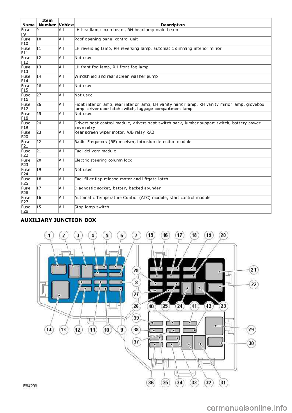
NameItemNumberVehicleDescription
FuseF99AllLH headlamp main beam, RH headlamp main beam
FuseF1010AllRoof openi ng panel cont rol unit
FuseF1111AllLH revers ing l amp, RH revers i ng lamp, automat ic di mmi ng int erior mi rror
FuseF1212AllNot us ed
FuseF1313AllLH front fog lamp, RH front fog lamp
FuseF1414AllW indshi eld and rear s creen was her pump
FuseF1528AllNot us ed
FuseF1627AllNot us ed
FuseF1726AllFront i nt eri or lamp, rear i nt eri or lamp, LH vanit y mirror l amp, RH vani ty mirror l amp, gl oveboxl amp, driver door l atch s wit ch, luggage compart ment lamp
FuseF1825AllNot us ed
FuseF1924AllDrivers s eat cont rol module, dri vers s eat swit ch pack, lumbar s upport s wi tch, bat t ery powers ave rel ayFuseF2023AllRear s creen wiper mot or, AJB rel ay RA2
FuseF2122AllRadio Frequency (RF) receiver, intrusi on detecti on module
FuseF2221AllFuel del ivery modul e
FuseF2320AllElect ric st eeri ng col umn lock
FuseF2419AllNot us ed
FuseF2518AllFuel fil ler flap release motor and l iftgate lat ch
FuseF2617AllDi agnos ti c s ocket, bat tery backed s ounder
FuseF2716AllAut omat ic Temperature Cont rol (ATC) modul e, st art control modul e
FuseF2815AllSt op lamp swi tch
AUXILIARY JUNCTION BOX
Page 1857 of 3229
1
1
1
1
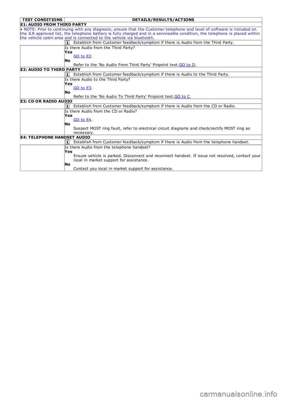
T EST CONDIT IO NSDET AILS/RESULT S/ACT IONS
E1: AUDIO FROM T HIRD PART Y
• NOTE: Prior to cont inuing wi th any di agnos is , ens ure t hat the Cus tomer t elephone and level of s oft ware is i ncl uded ont he JLR approved l is t , the t elephone bat tery is full y charged and in a s erviceabl e condi ti on, t he t elephone is placed wi thint he vehi cl e cabi n area and is connect ed to the vehicle vi a bluet oot h.Es tabli s h from Cus t omer feedback/s ymptom if t here i s Audio from t he Thi rd Party.
Is t here Audio from t he Thi rd Party?YesGO to E2.NoRefer t o t he 'No Audi o From Thi rd Party' Pinpoint t est .GO t o D.
E2: AUDIO T O T HIRD PART Y
Es tabli s h from Cus t omer feedback/s ymptom if t here i s Audio t o t he Third Part y.
Is t here Audio t o t he Third Part y?YesGO to E3.NoRefer t o t he 'No Audi o To Third Part y' Pi npoi nt t es t.GO t o C.
E3: CD O R RADIO AUDIO
Es tabli s h from Cus t omer feedback/s ymptom if t here i s Audio from t he CD or Radio.
Is t here Audio from t he CD or Radio?YesGO to E4.NoSus pect MOST ring fault , refer t o elect rical circuit di agrams and check/recti fy MOST ri ng asneces s ary.
E4: T ELEPHONE HANDSET AUDIOEs tabli s h from Cus t omer feedback/s ymptom if t here i s Audio from t he tel ephone hands et .
Is t here Audio from t he tel ephone hands et ?YesEns ure vehicle is parked. Dis connect and reconnect hands et. If is s ue not res olved, contact yourl ocal in market s upport for ass i st ance.NoContact you local in market support for as s is t ance.
Page 1859 of 3229
1
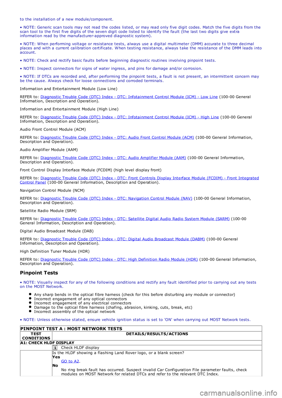
t o the ins tall ati on of a new module/component.
• NOTE: Generic scan t ool s may not read the codes li st ed, or may read only fi ve digit codes . Mat ch the five di git s from t hes can tool to the firs t fi ve di git s of the seven digi t code l is ted to ident ify t he faul t (t he las t t wo digi ts gi ve ext rainformat ion read by the manufact urer-approved diagnost ic s ys tem).
• NOTE: W hen performing volt age or res is t ance t est s , always use a digi tal mult imeter (DMM) accurat e t o t hree deci malplaces and wit h a current cal ibrat ion cert ificate. W hen tes ti ng res i st ance, always take the res is tance of the DMM l eads i ntoaccount.
• NOTE: Check and recti fy bas ic faul ts before beginni ng diagnos t ic rout ines i nvol vi ng pinpoint t es t s.
• NOTE: Ins pect connect ors for s igns of water ingres s , and pins for damage and/or corros ion.
• NOTE: If DTCs are recorded and, aft er performi ng the pi npoi nt tes ts , a fault is not present , an int ermi tt ent concern maybe t he caus e. Always check for loose connect ions and corroded terminals .
Informat ion and Ent ert ai nment Modul e (Low Line)
REFER to: Di agnos ti c Trouble Code (DTC) Index - DTC: Infotai nment Cont rol Modul e (ICM) - Low Li ne (100-00 GeneralInformat ion, Des cript ion and Operat ion).
Informat ion and Ent ert ai nment Modul e (High Line)
REFER to: Di agnos ti c Trouble Code (DTC) Index - DTC: Infotai nment Cont rol Modul e (ICM) - High Line (100-00 GeneralInformat ion, Des cript ion and Operat ion).
Audio Front Control Modul e (ACM)
REFER to: Di agnos ti c Trouble Code (DTC) Index - DTC: Audio Front Cont rol Modul e (ACM) (100-00 General Informati on,Des cript ion and Operat ion).
Audio Ampl ifier Modul e (AAM)
REFER to: Di agnos ti c Trouble Code (DTC) Index - DTC: Audio Ampl ifier Module (AAM) (100-00 General Informati on,Des cript ion and Operat ion).
Front Control Di s pl ay Int erface Modul e (FCDIM) (hi gh level di s pl ay front)
REFER to: Di agnos ti c Trouble Code (DTC) Index - DTC: Front Controls Di spl ay Int erface Module (FCDIM) - Front Int egratedControl Panel (100-00 General Informati on, Des cript ion and Operat ion).
Navigati on Cont rol Module (NCM)
REFER to: Di agnos ti c Trouble Code (DTC) Index - DTC: Navigati on Cont rol Module (NAV) (100-00 General Informat ion,Des cript ion and Operat ion).
Satell it e Radio Modul e (SRM)
REFER to: Di agnos ti c Trouble Code (DTC) Index - DTC: Satel lit e Di git al Audio Radi o Syst em Module (SARM) (100-00General Informat ion, Descri pti on and Operat ion).
Digi tal Audio Broadcast Modul e (DAB)
REFER to: Di agnos ti c Trouble Code (DTC) Index - DTC: Digi tal Audio Broadcas t Modul e (DABM) (100-00 GeneralInformat ion, Des cript ion and Operat ion).
High Defini ti on Tuner Module (HDR)
REFER to: Di agnos ti c Trouble Code (DTC) Index - DTC: High Defini ti on Radi o Module (HDR) (100-00 General Informat ion,Des cript ion and Operat ion).
Pinpoint Tests
• NOTE: Vis uall y ins pect for any of t he fol lowi ng condit ions and rect ify any faul t identi fied prior t o carryi ng out any tes tson t he MOST Net work.
Any s harp bends in the opt ical fibre harnes s (check for t hi s before dis turbing any module or connect or)Incorrect engagement of any opti cal connect orsIncorrect engagement of any elect rical connectorsDamage t o t he opt ical fi bre harnes s (chafing, abrasi on, ki nki ng, cuts , break, etc)Incorrect as s embly of t he opti cal network
• NOTE: Unles s ot herwis e s t at ed, ens ure vehi cl e igni ti on st atus is s et to 'ON' when carryi ng out MOST Network t est s .
PINPOINT TEST A : MOST NETWORK TESTS
T ESTCONDIT IONSDET AILS/RESULT S/ACT IONS
A1: CHECK HLDF DISPLAY
Check HLDF dis play
Is t he HLDF showi ng a flas hi ng Land Rover l ogo, or a blank s creen?YesGO to A2.NoNo ri ng break faul t has occurred. Sus pect invali d Car Configurat ion Fi le paramet er fault s , checkmodules on MOST Network for relat ed DTCs and refer t o t he rel evant DTC Index.
Page 1862 of 3229
1
1
2
3
1
1
1
2
3
1
2
3
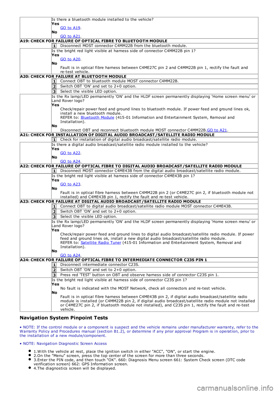
Is t here a bl uet ooth modul e ins t al led t o t he vehi cle?YesGO to A19.NoGO to A21.
A19: CHECK FOR FAILURE OF OPT ICAL FIBRE T O BLUET O OT H MODULE
Di sconnect MOST connect or C4MM22B from t he bluetoot h module.
Is t he bright red li ght vi si ble at harnes s s ide of connect or C4MM22B pi n 1?YesGO to A20.NoFault i s in opt ical fi bre harnes s between C4ME27C pin 2 and C4MM22B pin 1, recti fy the faul t andre-t est vehicle.
A20: CHECK FOR FAILURE AT BLUET OOT H MODULEConnect OBT to bl uet ooth modul e MOST connect or C4MM22B.
Swi tch OBT 'ON' and s et t o 2+0 opt ion.
Select t he vi s ible LED opt ion.
Is t he Rx lamp/LED permanentl y 'ON' and t he HLDF s creen permanentl y dis playing 'Home s creen menu' orLand Rover l ogo?YesCheck/repair power feed and ground lines t o bluet oot h module. If power feed and ground l ines ok,i nst all a new bl uetooth modul e.REFER t o: Bl uetooth Modul e (415-01 Informat ion and Ent ert ai nment Sys t em, Removal andInst all ati on).NoDi sconnect OBT and reconnect bl uetooth modul e MOST connect or C4MM22B.GO t o A21.
A21: CHECK FOR INST ALLAT ION O F DIGIT AL AUDIO BROADCAST /SAT ELLIT E RADIO MO DULECheck for i ns t allat ion of digi tal audio broadcast /sat elli te radio modul e.
Is t here a di gi tal audio broadcas t/sat ell it e radio module i nst all ed to the vehicle?YesGO to A22.NoGO to A24.
A22: CHECK FOR FAILURE OF OPT ICAL FIBRE T O DIGIT AL AUDIO BROADCAST /SAT ELLIT E R ADIO MODULEDi sconnect MOST connect or C4ME43B from t he digit al audio broadcas t/s atell it e radi o module.
Is t he bright red li ght vi si ble at harnes s s ide of connect or C4ME43B pin 1?YesGO to A23.NoFault i s in opt ical fi bre harnes s between C4MM22B pi n 2 (or C4ME27C pi n 2, if bl uet ooth modul e noti nst all ed) and C4ME43B pin 1, rect ify t he faul t and re-tes t vehi cl e.A23: CHECK FOR FAILURE AT DIGIT AL AUDIO BROADCAST /SAT ELLIT E RADIO MODULE
Connect OBT to di git al audio broadcas t/s at ell it e radi o module MOST connect or C4ME43B.
Swi tch OBT 'ON' and s et t o 2+0 opt ion.
Select t he vi s ible LED opt ion.
Is t he Rx lamp/LED permanentl y 'ON' and t he HLDF s creen permanentl y dis playing 'Home s creen menu' orLand Rover l ogo?YesCheck/repair power feed and ground lines t o digi tal audio broadcast /sat elli te radio modul e. If powerfeed and ground li nes ok, i nst all a new di git al audio broadcas t/s atell it e radi o module.REFER t o: Sat elli te Radi o Tuner (415-01 Informati on and Ent ert ainment Syst em, Removal andInst all ati on).NoGO to A24.A24: CHECK FOR FAILURE OF OPT ICAL FIBRE T O INT ERMEDIAT E CONNECT OR C23S PIN 1
Di sconnect i nt ermedi ate connect or C23S.
Swi tch OBT 'ON' and s et t o 2+0 opt ion.
Pres s red 'TEST' but ton on OBT and obs erve harnes s s ide of connector C23S pin 1.
Is t he bright red li ght vi si ble at harnes s s ide of connect or C23S pi n 1?YesNo fault i s indicat ed wit h t he MOST Net work, check all connectors and re-t es t vehicle.NoFault i s in opt ical fi bre harnes s between C4ME43B pin 2, if digi tal audi o broadcas t /s at el li te radiomodule is i nst all ed (or C4MM22B pi n 2, if digi tal audi o broadcast /s at el li te radio modul e not ins tal ledor C4ME27C pin 2, i f bluetooth module not ins t al led), and C23S pi n 1, recti fy the fault and re-t es tvehicle.
Navigation System Pinpoint Tests
• NOTE: If the control modul e or a component i s s us pect and the vehicle remains under manufacturer warrant y, refer t o theW arranty Pol icy and Procedures manual (s ect ion B1.2), or determine i f any pri or approval Program is i n operat ion, prior t ot he ins tal lati on of a new modul e/component.
• NOTE: Navigati on Diagnost ic Screen Access
1.W it h t he vehi cl e at res t , pl ace the i gnit ion s wit ch in eit her "ACC", "ON", or s t art t he engi ne.2.On the "Menu" screen, pres s t he t op cent er of t he s creen for more t han three s econds.3.Ent er t he PIN code, and t hen touch "OK". 660: Diagnosi s Menu s creen 661: Sys tem Check screen (DTC codeverificati on s creen) 662: GPS Informati on s creen.4.The di agnos ti cs screen will be di spl ayed.
Page 1863 of 3229
1
1
1
1
1
1
1
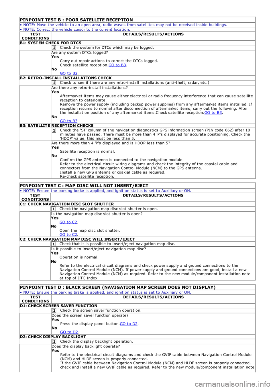
PINPOINT TEST B : POOR SATELLITE RECEPTION
• NOTE: Move t he vehi cl e t o an open area, radi o waves from s at el li tes may not be recei ved ins ide buil dings.
• NOTE: Correct the vehicle cursor t o t he current locati on.
T ESTCONDIT IONSDET AILS/RESULT S/ACT IONS
B1: SYST EM CHECK FOR DT CS
Check the s ys tem for DTCs whi ch may be logged.
Are any s ys t em DTCs l ogged?YesCarry out repair acti ons to correct the DTCs logged.Check sat ell it e recepti on.GO t o B3.NoGO to B2.
B2: RET RO-INST ALL INST ALLAT IONS CHECKCheck to see if t here are any ret ro-i nst all i ns t allat ions (ant i-t heft, radar, etc.)
Are there any ret ro-ins tal l i nst all ati ons ?YesAftermarket it ems may caus e eit her el ect ri cal or radio frequency int erference that can caus e s atel lit erecepti on t o deteriorat e.Remove t he power s upply (including backup power s upplies ) from any aft ermarket i tems i nst all ed. Ifrecepti on ret urns t o normal after dis connecti on of aft ermarket i tems , carry out the foll owing. Alt ert he ins t al lat ion pos it ion of any aft ermarket i tems.Check s atel li te recept ion.GO to B3.NoGO to B3.
B3: SAT ELLIT E R ECEPT ION CHECKSCheck the 'ST' column of t he navigati on diagnos t ics GPS i nformat ion screen (PIN code 662) after 10mi nutes have pass ed. There mus t be more t han 4 ‘P’s dis played for accurat e pos it ioning. Check t he‘HDOP’ value, t hi s mus t be l es s t han 5.
Are there more than 4 'P's di s pl ayed and is HDOP les s than 5?YesSatel li te recept ion i s normal .NoConfi rm t he GPS antenna is connect ed t o t he navi gat ion modul e.Refer t o t he electrical ci rcuit wi ri ng diagrams and check the integrit y of the coaxial cable andconnectors from the Navigat ion Control Modul e (NCM) to the GPS ant enna.Inst all a new GPS antenna or coaxial cabl e as requi red.Re-check s at ell it e recepti on.
PINPOINT TEST C : MAP DISC WILL NOT INSERT/EJECT
• NOTE: Ens ure t he parking brake is appli ed, and i gnit ion s tat us is set t o Auxil iary or ON.
T ESTCONDIT IONSDET AILS/RESULT S/ACT IONS
C1: CHECK NAVIGAT ION DISC SLO T SHUT T ER
Check the navigat ion map dis c s lot s hut t er i s open.
Is t he navi gat ion map dis c s lot s hutt er is open?YesGO t o C2.NoOpen t he map di s c s lot s hut ter.GO t o C2.
C2: CHECK NAVIGAT ION MAP DISC WILL INSERT /EJECTCheck that i t is pos s ible to i nsert/eject navi gat ion map dis c.
Is it pos s ible to ins ert /eject navi gati on map dis c?YesOperat ion is normal.NoRefer t o t he electrical ci rcuit di agrams and check power s uppl y and ground connecti ons to theNavigat ion Control Modul e (NCM). If power s upply and ground connect ions are good, ins t al l a newNavigat ion Control Modul e (NCM) as required. Refer t o t he new module/component ins tal lat ion noteat t op of DTC Index.
PINPOINT TEST D : BLACK SCREEN (NAVIGATION MAP SCREEN DOES NOT DISPLAY)
• NOTE: Ens ure t he parking brake is appli ed, and i gnit ion s tat us is set t o Auxil iary or ON.
T ESTCONDIT IONSDET AILS/RESULT S/ACT IONS
D1: CHECK SCREEN SAVER FUNCT IONCheck the s creen s aver funct ion operat ion.
Does the screen saver functi on operate?YesPres s t he dis play panel but ton.GO t o D2.NoGO to D2.
D2: CHECK DISPLAY BACKLIGHT
Check the di spl ay backli ght operat ion.
Does the di s pl ay backli ght operat e?YesRefer t o t he electrical ci rcuit diagrams and check t he GVIF cable bet ween Navigati on Cont rol Module(NCM) and HLDF s creen is properly connect ed.If the GVIF cable bet ween Navi gat ion Cont rol Modul e (NCM) and HLDF s creen is properly connect ed,check and i nst all a new GVIF cable as required. Refer t o t he new module/component ins tal lati on note
Page 1867 of 3229
Publi s hed: 11-May-2011
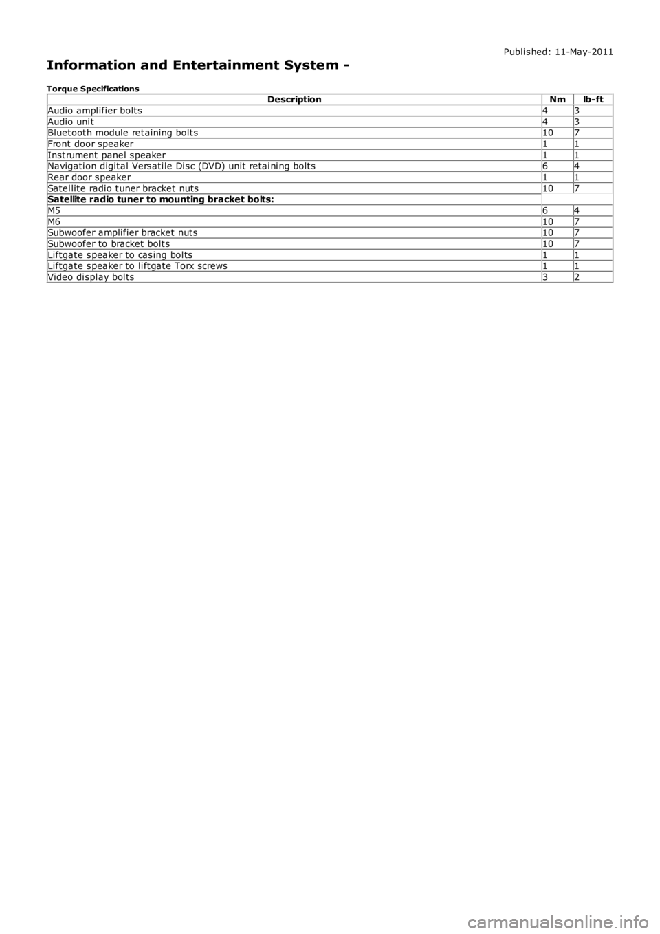
Information and Entertainment System -
Torque SpecificationsDescriptionNmlb-ft
Audio ampl ifier bolt s43
Audio uni t43Bluet oot h module ret aining bolt s107
Front door speaker11
Inst rument panel s peaker11Navigati on digit al Vers ati le Di s c (DVD) unit retai ni ng bolt s64
Rear door s peaker11
Satel lit e radio t uner bracket nuts107Satellite radio tuner to mounting bracket bolts:
M564
M6107Subwoofer amplifier bracket nut s107
Subwoofer to bracket bolt s107
Liftgat e s peaker to cas ing bol ts11Liftgat e s peaker to li ft gat e Torx screws11
Video di spl ay bol ts32