2006 LAND ROVER FRELANDER 2 radio
[x] Cancel search: radioPage 1953 of 3229
5-Rear door module
6-Rear i nterior lamp
7-Luggage compart ment lamp8-Rear door lat ch swit ch
9-Rear door module
10-Dri ver door lat ch swi tch11-Dri ver door lamp
12-Dri ver door module
13-Ext eri or mirror lamp14-Vani ty mirror l amp
15-Dri ver foot well l amp
16-Pas s enger foot well l amp17-Cent ral Junct ion Box (CJB)
18-Pas s enger door lamp
19-Glovebox lamp20-Pas s enger door module
21-Ext eri or mirror lamp
22-Pas s enger door lat ch swi tch
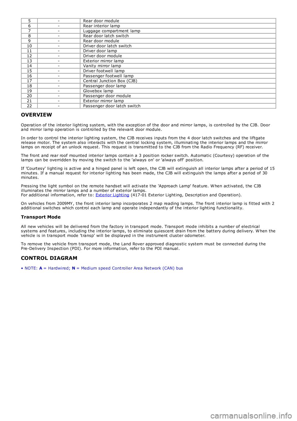
OVERVIEW
Operat ion of t he int erior l ighti ng s ys t em, wit h t he excepti on of the door and mi rror lamps , is controlled by the CJB. Doorand mi rror l amp operat ion i s cont rol led by t he rel evant door modul e.
In order to cont rol t he int erior l ighti ng s ys t em, the CJB recei ves i nput s from the 4 door l atch s wit ches and the l iftgat erel eas e motor. The s ys tem als o i nt eracts wit h t he cent ral locking s ys tem, i lluminating the interior lamps and the mirrorlamps on receipt of an unlock request . This reques t is trans mi tt ed t o t he CJB from the Radio Frequency (RF) receiver.
The front and rear roof mounted interior lamps contai n a 3 pos i ti on rocker s wi tch. Aut omati c (Courtes y) operati on of thelamps can be overridden by movi ng the s wi tch t o t he 'al ways on' or 'always off' positi on.
If 'Court es y' li ght ing i s acti ve and a hinged panel i s left open, t he CJB wil l ext inguis h all i nterior lamps after a period of 15mi nut es. If a manual request for int erior l ighti ng has been made, t he CJB wi ll exti nguis h the l amps aft er a peri od of 30mi nut es.
Pres s ing t he li ght symbol on t he remot e hands et wi ll act ivat e t he 'Approach Lamp' feat ure. W hen act ivated, t he CJBil lumi nat es t he mirror l amps and a number of ext eri or l amps.For addit ional informat ion, refer t o: Ext eri or Li ght ing (417-01 Ext erior Light ing, Descri pti on and Operat ion).
On vehicles from 2009MY , t he front int erior l amp incorporat es 2 map reading l amps. The front i nt eri or lamp i s fit ted wi th 2addi ti onal s wi tches which cont rol each lamp and operate i ndependant ly of t he i nt eri or light ing funct ionalit y.
Transport Mode
All new vehicles will be del ivered from the factory in t rans port mode. Trans port mode i nhi bit s a number of el ect ri cals ys t ems and feat ures , including t he i nt eri or lamps , to el imi nate qui es cent drain from t he bat t ery duri ng delivery. W hen thevehi cl e i s in trans port mode 't ransp' wi ll be dis played i n the ins trument cl us t er odomet er.
To remove the vehicle from t rans port mode, the Land Rover approved di agnos ti c s ys t em mus t be connect ed during t hePre-Delivery Ins pect ion (PDI). For more i nformati on, refer t o the PDI manual .
CONTROL DIAGRAM
• NOTE: A = Hardwi red; N = Medium s peed Cont roll er Area Net work (CAN) bus
Page 1964 of 3229
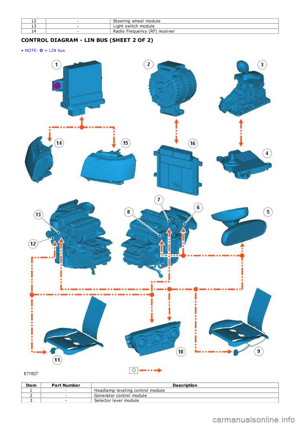
12-St eering wheel module
13-Li ght s wi tch module
14-Radio Frequency (RF) recei ver
CONTROL DIAGRAM - LIN BUS (SHEET 2 OF 2)
• NOTE: O = LIN bus
ItemPart NumberDescription
1-Headlamp level ing control modul e
2-Generat or control modul e3-Selector l ever module
Page 1968 of 3229
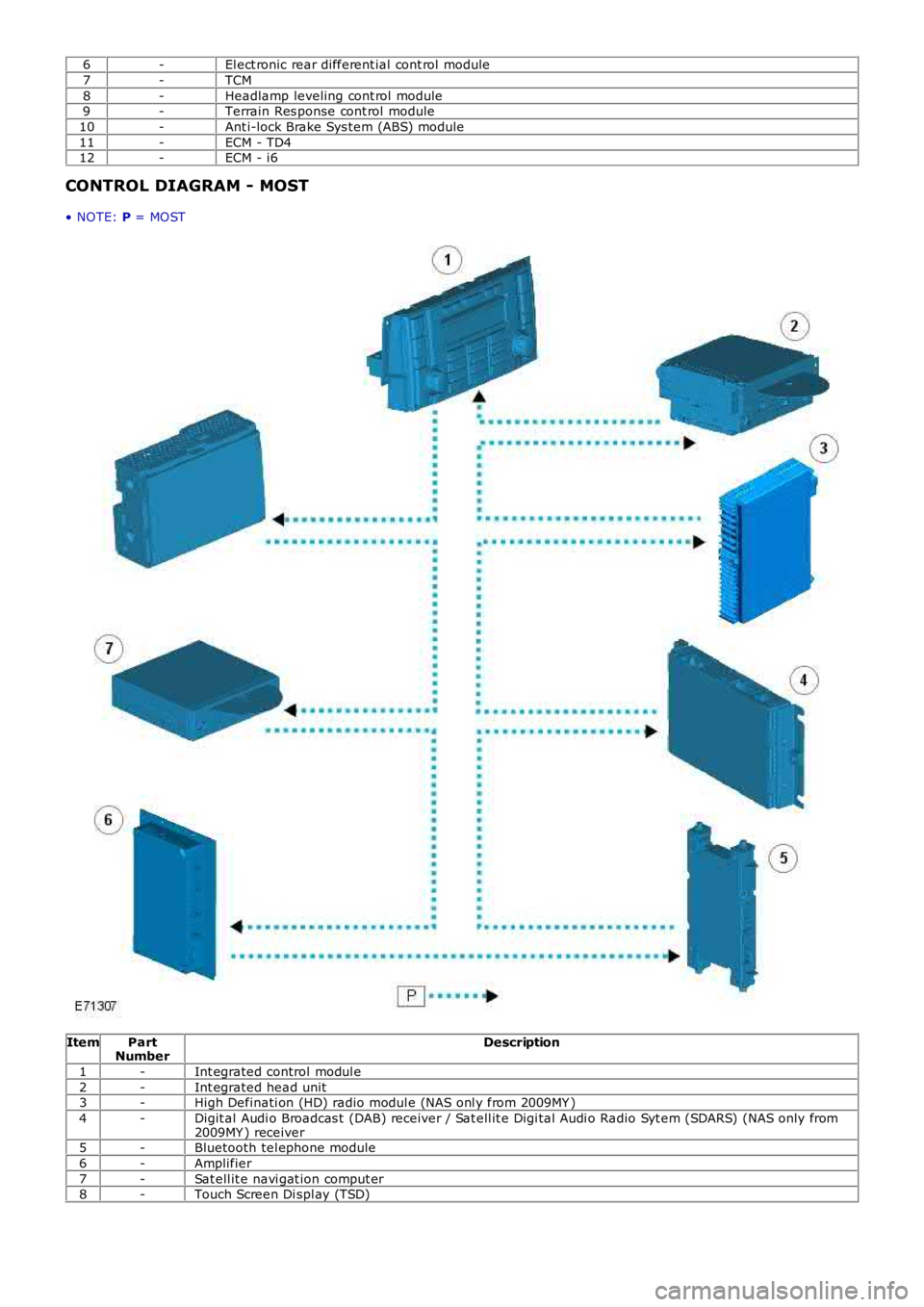
6-El ect ronic rear different ial cont rol module
7-TCM
8-Headlamp leveling cont rol module9-Terrain Res ponse cont rol module
10-Ant i-lock Brake Sys tem (ABS) module
11-ECM - TD412-ECM - i6
CONTROL DIAGRAM - MOST
• NOTE: P = MOST
ItemPartNumberDescription
1-Int egrated control modul e
2-Int egrated head unit3-High Definati on (HD) radio modul e (NAS onl y from 2009MY )
4-Digit al Audi o Broadcas t (DAB) receiver / Sat ell it e Digi tal Audi o Radio Syt em (SDARS) (NAS only from2009MY ) receiver5-Bluetooth tel ephone module
6-Amplifier
7-Sat ell it e navi gat ion comput er8-Touch Screen Di spl ay (TSD)
Page 2047 of 3229
Publi s hed: 11-May-2011
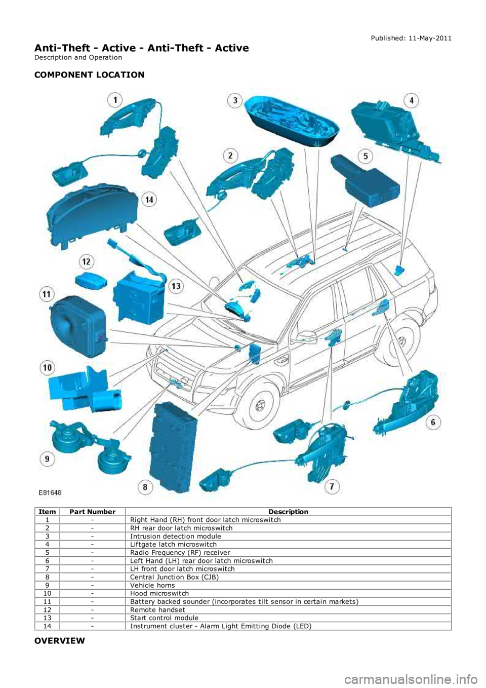
Anti-Theft - Active - Anti-Theft - Active
Des cript ion and Operat ion
COMPONENT LOCATION
ItemPart NumberDescription1-Ri ght Hand (RH) front door l at ch mi croswit ch
2-RH rear door l atch mi cros wit ch
3-Intrusi on detecti on module4-Lift gat e l at ch mi croswi tch
5-Radio Frequency (RF) recei ver
6-Left Hand (LH) rear door latch micros wit ch7-LH front door lat ch micros wi tch
8-Central Juncti on Box (CJB)
9-Vehicle horns10-Hood micros wit ch
11-Bat tery backed s ounder (incorporates t il t s ens or in certai n market s)
12-Remot e hands et13-St art cont rol module
14-Inst rument clus t er - Al arm Light Emit t ing Di ode (LED)
OVERVIEW
Page 2058 of 3229
Publi s hed: 11-May-2011
Anti-Theft - Passive - Anti-Theft - Passive
Des cript ion and Operat ion
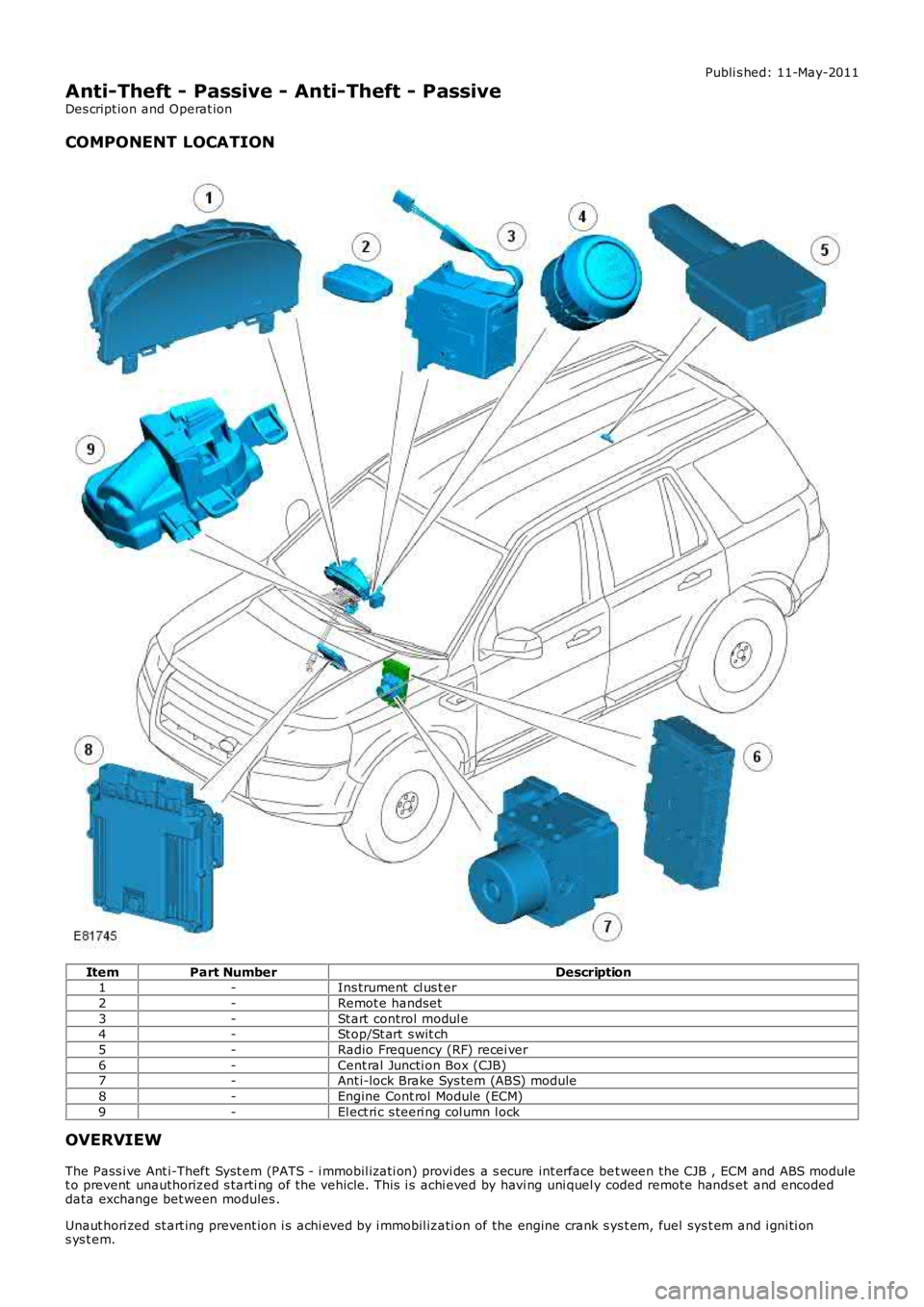
COMPONENT LOCATION
ItemPart NumberDescription1-Ins trument cl us t er
2-Remot e handset
3-St art control modul e4-St op/St art s wit ch
5-Radio Frequency (RF) recei ver
6-Cent ral Juncti on Box (CJB)7-Ant i-lock Brake Sys tem (ABS) module
8-Engine Cont rol Module (ECM)
9-El ect ri c s teeri ng col umn l ock
OVERVIEW
The Pass i ve Ant i-Theft Syst em (PATS - i mmobil izati on) provi des a s ecure int erface bet ween the CJB , ECM and ABS modulet o prevent unauthorized s tarti ng of the vehicle. This i s achi eved by havi ng uni quel y coded remote hands et and encodeddata exchange bet ween modules .
Unaut hori zed st art ing prevent ion i s achi eved by i mmobil izati on of the engine crank sys t em, fuel sys t em and i gni ti ons ys t em.
Page 2061 of 3229
opened. The remot e handset i s removed from the st art control modul e by gentl y pushi ng the remote hands et int o t he st artcont rol module and releas ing. The s tart cont rol module mot or wil l then drive t he remot e hands et out from t he s lot as l ongas t he ignit ion i s off.
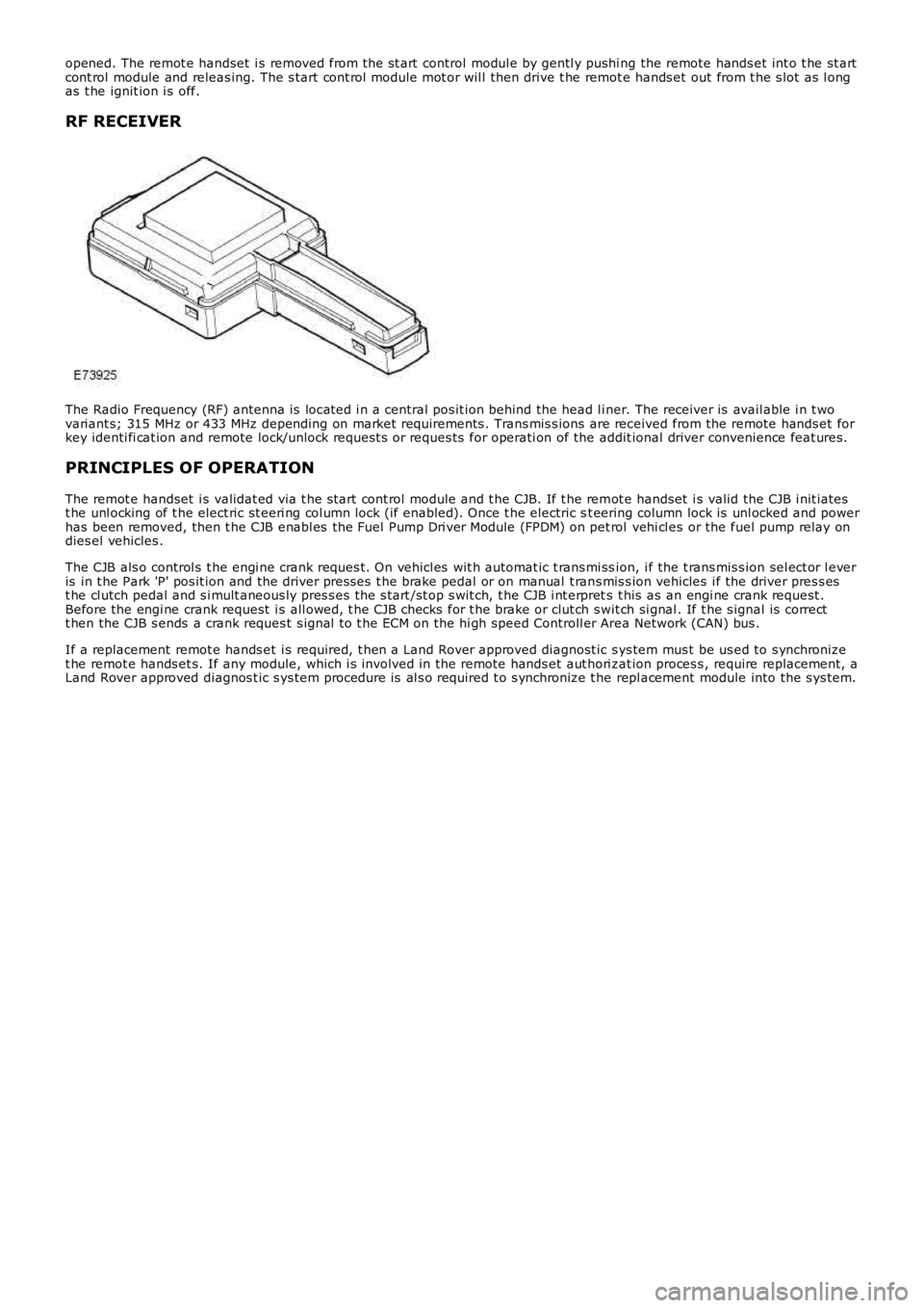
RF RECEIVER
The Radio Frequency (RF) antenna is locat ed i n a central pos it ion behind the head l iner. The receiver is avail able i n t wovariant s; 315 MHz or 433 MHz depending on market requirements . Trans mis s ions are received from the remote hands et forkey identi fi cat ion and remote lock/unlock request s or reques ts for operati on of the addit ional driver convenience feat ures.
PRINCIPLES OF OPERATION
The remot e handset i s validat ed via t he s tart cont rol module and t he CJB. If t he remot e handset i s valid the CJB i nit iatest he unl ocking of t he elect ric st eeri ng col umn lock (if enabled). Once t he electric st eering column lock is unl ocked and powerhas been removed, then t he CJB enabl es the Fuel Pump Dri ver Module (FPDM) on pet rol vehi cl es or the fuel pump relay ondies el vehicles .
The CJB als o control s t he engi ne crank reques t. On vehicl es wit h automat ic t rans mi ssion, i f the t rans mis s ion sel ect or l everis in t he Park 'P' pos it ion and the driver pres ses t he brake pedal or on manual t rans mis s ion vehicles i f the driver pres s est he cl utch pedal and s i mult aneous ly pres s es t he s tart /st op s wit ch, t he CJB i nt erprets t his as an engi ne crank request .Before the engi ne crank request i s all owed, t he CJB checks for t he brake or clut ch swit ch si gnal . If t he s ignal is correctt hen the CJB s ends a crank reques t s ignal t o t he ECM on the hi gh speed Controll er Area Network (CAN) bus .
If a replacement remot e hands et i s required, t hen a Land Rover approved diagnost ic sys tem mus t be us ed to s ynchronizet he remot e hands et s. If any module, which i s involved in the remote hands et aut hori zat ion proces s , require replacement, aLand Rover approved diagnos t ic s ys tem procedure is al s o required t o s ynchronize t he repl acement module into the s ys tem.
Page 2073 of 3229
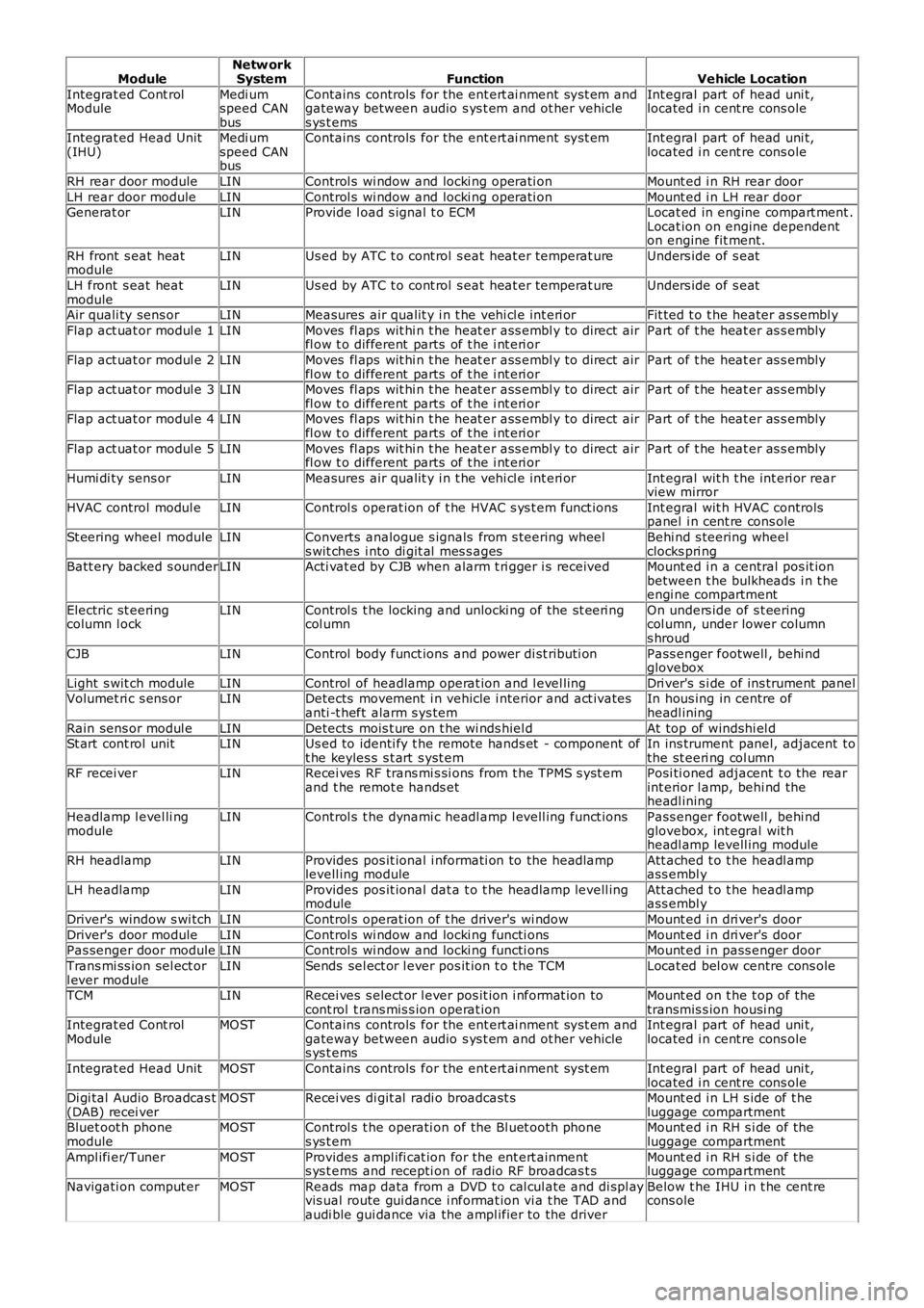
ModuleNetw orkSystemFunctionVehicle Location
Integrat ed Cont rolModuleMedi umspeed CANbus
Contains controls for the ent ert ai nment sys t em andgateway between audio s ys t em and ot her vehicles ys t ems
Int egral part of head uni t,located i n cent re cons ole
Integrat ed Head Unit(IHU)Medi umspeed CANbus
Contains controls for the ent ert ai nment sys t emInt egral part of head uni t,located i n cent re cons ole
RH rear door moduleLINControl s wi ndow and locki ng operati onMount ed i n RH rear door
LH rear door moduleLINControl s wi ndow and locki ng operati onMount ed i n LH rear doorGenerat orLINProvide l oad s ignal t o ECMLocat ed in engine compart ment .Locat ion on engine dependenton engine fit ment.
RH front s eat heatmoduleLINUs ed by ATC t o cont rol s eat heat er temperat ureUnders ide of s eat
LH front s eat heatmoduleLINUs ed by ATC t o cont rol s eat heat er temperat ureUnders ide of s eat
Air quali ty sens orLINMeasures air qualit y i n t he vehi cl e int eri orFit ted t o t he heater as sembl y
Flap act uat or modul e 1LINMoves fl aps wit hi n t he heat er ass embl y to direct airfl ow t o different parts of t he i nt eri orPart of t he heat er as s embly
Flap act uat or modul e 2LINMoves fl aps wit hi n t he heat er ass embl y to direct airfl ow t o different parts of t he i nt eri orPart of t he heat er as s embly
Flap act uat or modul e 3LINMoves fl aps wit hi n t he heat er ass embl y to direct airfl ow t o different parts of t he i nt eri orPart of t he heat er as s embly
Flap act uat or modul e 4LINMoves fl aps wit hi n t he heat er ass embl y to direct airfl ow t o different parts of t he i nt eri orPart of t he heat er as s embly
Flap act uat or modul e 5LINMoves fl aps wit hi n t he heat er ass embl y to direct airfl ow t o different parts of t he i nt eri orPart of t he heat er as s embly
Humi di ty sens orLINMeasures air qualit y i n t he vehi cl e int eri orInt egral wit h t he int eri or rearview mirror
HVAC control modul eLINControl s operat ion of t he HVAC s ys t em funct ionsInt egral wit h HVAC controlspanel i n cent re cons ole
St eering wheel moduleLINConverts analogue s ignals from s teering wheels wit ches i nto di git al mes s agesBehi nd s teering wheelclocks pri ngBatt ery backed s ounderLINActi vat ed by CJB when alarm t ri gger i s receivedMount ed i n a central pos it ionbetween t he bulkheads i n t heengi ne compartment
Electric st eeringcolumn l ockLINControl s t he locking and unlocki ng of the st eeri ngcol umnOn unders ide of s t eeringcol umn, under lower columns hroud
CJBLINControl body funct ions and power di st ributi onPass enger footwell , behi ndglovebox
Light s wit ch moduleLINControl of headlamp operat ion and l evel lingDri ver's s i de of ins trument panelVolumet ri c s ens orLINDetects movement i n vehicle i nterior and act ivatesanti -t heft alarm s ys temIn hous ing in centre ofheadl ining
Rain sens or modul eLINDetects mois t ure on t he wi nds hiel dAt top of windshi el dSt art cont rol unitLINUs ed to identi fy t he remote hands et - component oft he keyles s s t art s yst emIn ins trument panel, adjacent tothe st eeri ng col umnRF recei verLINRecei ves RF trans mi s si ons from t he TPMS s yst emand t he remot e hands etPosi ti oned adjacent t o the rearint erior l amp, behi nd theheadl ining
Headlamp l evel li ngmoduleLINControl s t he dynami c headl amp l evell ing funct ionsPass enger footwell , behi ndglovebox, int egral wit hheadl amp levell ing module
RH headlampLINProvides pos it ional i nformati on to the headlamplevell ing moduleAtt ached t o t he headl ampass embl y
LH headlampLINProvides pos it ional dat a t o t he headlamp levell ingmoduleAtt ached t o t he headl ampass embl y
Driver's window s wi tchLINControl s operat ion of t he driver's wi ndowMount ed i n dri ver's door
Driver's door moduleLINControl s wi ndow and locki ng functi onsMount ed i n dri ver's doorPas senger door moduleLINControl s wi ndow and locki ng functi onsMount ed i n pass enger door
Trans mi ss ion sel ect orl ever moduleLINSends sel ect or l ever pos it ion t o t he TCMLocat ed bel ow centre cons ole
TCMLINRecei ves s elect or l ever pos it ion i nformat ion tocont rol t rans mis s ion operat ionMount ed on t he t op of thetransmis s ion housi ngIntegrat ed Cont rolModuleMOSTContains controls for the ent ert ai nment sys t em andgateway between audio s ys t em and ot her vehicles ys t ems
Int egral part of head uni t,located i n cent re cons ole
Integrat ed Head UnitMOSTContains controls for the ent ert ai nment sys t emInt egral part of head uni t,located i n cent re cons oleDi gi tal Audio Broadcas t(DAB) recei verMOSTRecei ves di git al radi o broadcast sMount ed i n LH s ide of t heluggage compartmentBluet oot h phonemoduleMOSTControl s t he operati on of the Bl uet ooth phones ys t emMount ed i n RH s i de of theluggage compartment
Ampl ifi er/TunerMOSTProvides ampl ifi cat ion for the ent ert ainments ys t ems and recepti on of radio RF broadcas t sMount ed i n RH s i de of theluggage compartment
Navigati on comput erMOSTReads map data from a DVD t o cal cul ate and di spl ayvis ual route gui dance i nformat ion vi a t he TAD andaudi ble gui dance via the ampl ifier to the driver
Below t he IHU i n t he cent recons ole
Page 2193 of 3229
Publi s hed: 11-May-2011
Seating - Front Seat Backrest Cover
Removal and Inst all ati on
Removal
• W ARNINGS:
To avoid accidental depl oyment , t he res traint s cont rol module backup power s upply mus t be deplet ed. W ait at leas tone mi nut e after dis connecti ng the bat tery ground cabl e(s ) before commenci ng any repair or adjus tment t o t hes uppl ement al res traint s yst em (SRS), or any component(s ) adjacent t o t he SRS s ens ors. Fail ure t o follow thes eins t ructi ons may res ult i n pers onal i njury.
Al ways wear s afet y glas s es when working on an air bag equipped vehi cl e and when handl ing an ai r bag module.Failure t o fol low this ins truct ion may res ult i n pers onal i njury.
To minimize t he pos s ibi lit y of premat ure depl oyment , do not us e radio key code s avers when working on thes uppl ement al res traint s yst em. Failure t o fol low this ins truct ion may res ult i n personal i njury.
To minimize t he pos s ibi lit y of i njury i n t he event of premat ure depl oyment , al ways carry a li ve air bag module wit ht he bag and trim cover point ed away from t he body. Fail ure t o follow thi s ins t ructi on may res ult i n pers onal injury.
To minimize t he pos s ibi lit y of premat ure depl oyment , live ai r bag modules mus t only be pl aced on work bencheswhich have been ground bonded and wit h t he trim cover facing up. Fail ure t o follow thes e i ns t ructi ons may res ult i npers onal i njury.
Never probe t he elect rical connect ors of air bag modules or any ot her s upplemental res t rai nt s ys tem component.Failure t o fol low this ins truct ion may res ult i n pers onal i njury.
Paint ing over the driver air bag module trim cover or ins trument panel coul d lead to det eriorat ion of t he t ri m coverand air bags. Do not for any reas on att empt to pai nt dis col ored or damaged air bag module trim covers or i nst rumentpanel . Ins tal l a new component . Fai lure to foll ow t his i nst ruct ion may res ul t in pers onal injury.
Make s ure that s ufficient ti me has el aps ed aft er dis connecti ng the bat tery ground cabl e(s ), before commencing workon t he s uppl ement al res traint s ys t em (SRS). Fail ure t o fol low thes e ins t ructi ons may res ult i n pers onal i njury.
• NOTE: Removal s t eps in t his procedure may cont ain i nst all ati on det ail s.
Di sconnect t he bat t ery ground cable.
Refer t o: Specificati ons (414-00 Bat tery and Charging Sys tem -General Informat ion, Specificati ons).
1.
Make t he SRS s ys t em s afe.
Refer t o: Standard W orks hop Pract ices (100-00 General Informat ion,Des cript ion and Operat ion).
2.
Remove t he front safet y belt buckle.
Refer t o: Front Safety Bel t Buckle (501-20A Safet y Belt Sys tem,Removal and Ins tall ati on).
3.