Page 3357 of 5267
U0121-LOST COMMUNICATION WITH ABS
For a complete wiring diagramRefer to Section 8W.
Page 3359 of 5267
U0141 LOST COMMUNICATION WITH FCM
For a complete wiring diagramRefer to Section 8W.
Page 3361 of 5267
45RFE/545RFE PRE-DIAGNOSTIC TROUBLESHOOTING PROCEDURE
For a complete wiring diagramRefer to Section 8W.
1.
Perform the following before attempting any diagnostic procedures:
Check the transmission fluid level. Ifthe fluid level is low, locate and repair any leaks and fill the transmission
to the proper level. Refer to the appropriate Service Information for procedures. Many transmission symptoms
can be caused by a low fluid level.
Check the battery. To avoid false diagnosis, testing should only be performed with the battery fully charged.
With the scan tool, read Engine (PCM) DTCs. If DTCs are present, refer to theDriveability Category and per-
form to the appropriate diagnostic procedure(s) before proceeding.
With the scan tool, read Transmission (TCM) DTCs. Record all Stored, Active, and Pending DTC information.
Diagnose any Pending DTC as a matured DTC.
With the scan tool, read DTC EVENT DATA.Use this data to identify the conditions in which the DTC was set.
Performing a Battery Disconnect will clear all DTC EVENT DATA and reset alllearned Transmission values to
the default values, which may temporarily result in erratic shift schedules.
With the scan tool, perform the Shift Lever Position Test. If the test does not pass, refer to the diagnostic
procedure for P0706 Transmission Range Sensor Rationality.
For Gear Ratio Error DTCs, use the scan tool to view CVI Monitor data. Read and record the Clutch Volume
Index information.
Use the wiring diagram as a guide. Inspect the wiring and connectors related to this circuit. Repair as neces-
sary.
Refer to the When Monitored and Set Conditions for this DTC. DTCs can set at ignition on, at start up, after
driving under specific conditions and after diagnostic monitors have beenrun.
Refer to applicable Technical Service Bulletins (TSBs) for controller software update information. Some condi-
tions can be corrected by upgrading the Engine (PCM) or Transmission (TCM)controller software.
Refer to any Service Information Tune Ups or Technical Service Bulletins that apply.
Were there any repairs made that fixed the vehicle?
Ye s>>
Testing complete.
Perform 45RFE/545RFE TRANSMISSION VERIFICATION TEST - VER 1. (Refer to 21- TRANSMIS-
SION/TRANSAXLE/AUTOMATIC - 45RFE/545RFE - STANDARD PROCEDURE)
No>>
Refer to the Transmission category and perform the appropriate diagnostic procedure(s).
Page 3362 of 5267
45RFE/545RFE TRANSMISSION VERIFICATION TEST - VER 1
For a complete wiring diagramRefer to Section 8W.
1.
Perform the following after completion of a diagnostic repair:
After completion of the Transmission Verification Test, the Powertrain Verification Test must be per-
formed.
Connect the scan tool to the Data Link Connector (DLC).
Reconnect any disconnected components.
If the PCM has been replaced or updated (flashed), or the transmission has been repaired or replaced, using
the scan tool, perform a Quick Learn Procedure.
With the scan tool, erase all Transmission and Engine DTC’s.
With the scan tool, perform a BATTERY DISCONNECT, this will clear the DTC EVENT DATA
With the scan tool, display Transmission Temperature. Start and run the engine until the Transmission Tem-
perature is HOT.
Check the Transmission fluid level and adjust if necessary. Refer to the Service Information for the Fluid Fill
procedure. (Refer to 21 - TRANSMISSION/TRANSAXLE/AUTOMATIC - 45RFE/545RFE/FLUID - STANDARD
PROCEDURE)
Road test the vehicle.
Perform the following shifts from a standing start with a constant throttle opening of 20 to 25 degrees to the
speeds of 97 Kmh (60 mph); make fifteen to twenty 1 to 2, 2 to 3, 3 to 4 upshifts andfor545RFE,4to5.
Perform the following shifts with speeds below 40 Kmh (25 mph); make five toeight wide open throttle kick-
downs to 1st gear. Allow at least 5 seconds each in 2nd and 3rd gear between each kickdown.
Check for DTCs during and after the road test.
If after performing the road test, if any shift concerns are noted, performthe drive learn procedure for those
affected shifts. (Refer to 8 - ELECTRICAL/ELECTRONIC CONTROL MODULES/TRANSMISSION CONTROL
MODULE - STANDARD PROCEDURE)
Use the EATX OBDII task manager to run Good Trip time in each gear, this will confirm the repair and
to ensure that the DTC does not re-mature.
Were there any Diagnostic Trouble Codes (DTCs) set during the road test?
Ye s>>
Refer to the Transmission category and perform the appropriate symptom. (Refer to 21 - TRANSMIS-
SION/TRANSAXLE/AUTOMATIC - 45RFE/545RFE - DIAGNOSIS AND TESTING)
No>>
Repair is complete.
Page 3435 of 5267
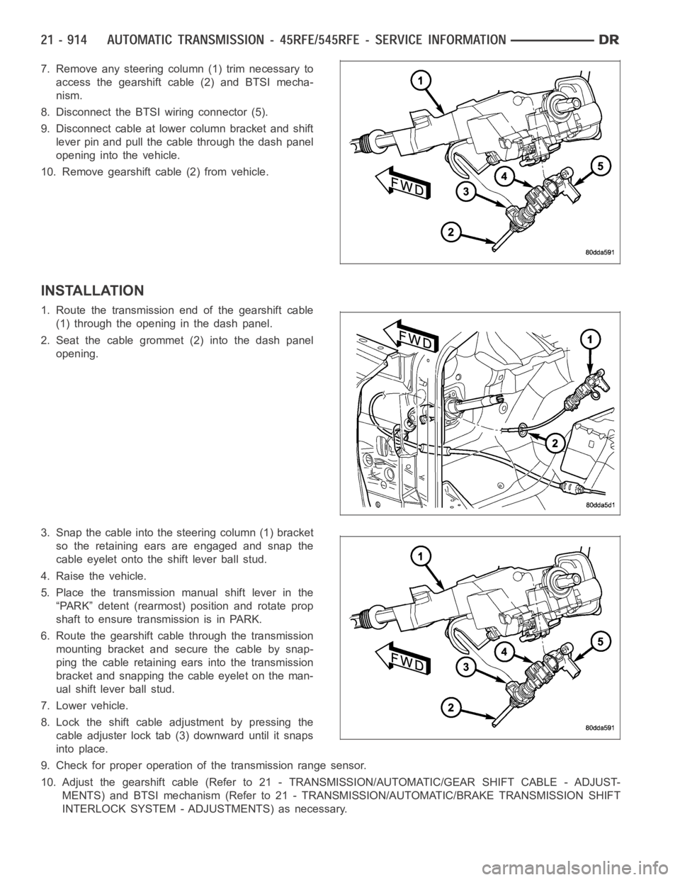
7. Remove any steering column (1) trim necessary to
access the gearshift cable (2) and BTSI mecha-
nism.
8. Disconnect the BTSI wiring connector (5).
9. Disconnect cable at lower column bracket and shift
lever pin and pull the cable through the dash panel
opening into the vehicle.
10. Remove gearshift cable (2) from vehicle.
INSTALLATION
1. Route the transmission end of the gearshift cable
(1) through the opening in the dash panel.
2. Seat the cable grommet (2) into the dash panel
opening.
3. Snap the cable into the steering column (1) bracket
so the retaining ears are engaged and snap the
cable eyelet onto the shift lever ball stud.
4. Raise the vehicle.
5. Place the transmission manual shift lever in the
“PARK” detent (rearmost) position and rotate prop
shaft to ensure transmission is in PARK.
6. Route the gearshift cable through the transmission
mounting bracket and secure the cable by snap-
ping the cable retaining ears into the transmission
bracket and snapping the cable eyelet on the man-
ual shift lever ball stud.
7. Lower vehicle.
8. Lock the shift cable adjustment by pressing the
cable adjuster lock tab (3) downward until it snaps
into place.
9. Check for proper operation of the transmission range sensor.
10. Adjust the gearshift cable (Refer to 21 - TRANSMISSION/AUTOMATIC/GEAR SHIFT CABLE - ADJUST-
MENTS) and BTSI mechanism (Refer to 21 - TRANSMISSION/AUTOMATIC/BRAKE TRANSMISSION SHIFT
INTERLOCK SYSTEM - ADJUSTMENTS) as necessary.
Page 3453 of 5267
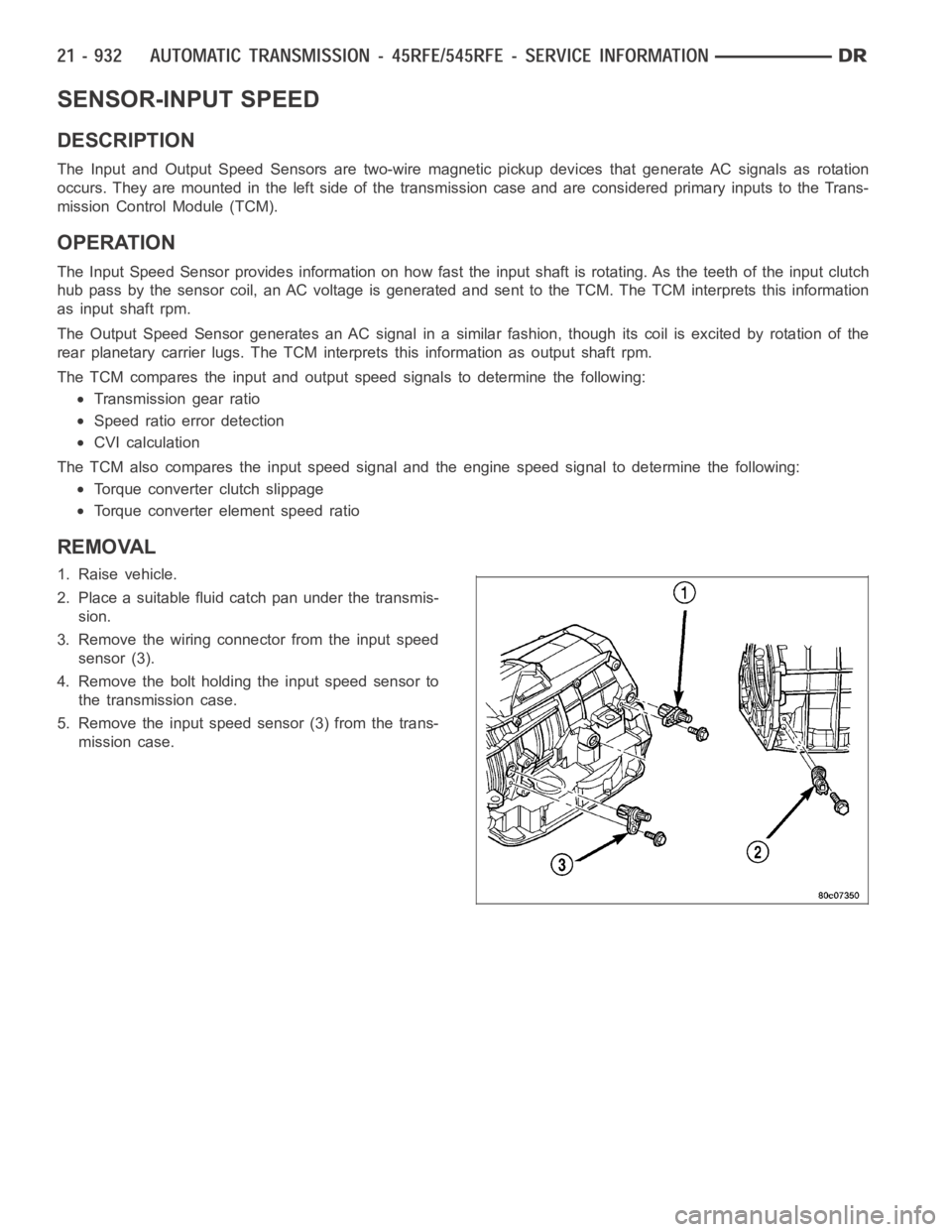
SENSOR-INPUT SPEED
DESCRIPTION
The Input and Output Speed Sensors are two-wire magnetic pickup devices that generate AC signals as rotation
occurs. They are mounted in the left side of the transmission case and are considered primary inputs to the Trans-
mission Control Module (TCM).
OPERATION
The Input Speed Sensor provides information on how fast the input shaft is rotating. As the teeth of the input clutch
hub pass by the sensor coil, an AC voltage is generated and sent to the TCM. The TCM interprets this information
as input shaft rpm.
The Output Speed Sensor generates an AC signal in a similar fashion, thoughitscoilisexcitedbyrotationofthe
rear planetary carrier lugs. The TCM interprets this information as outputshaftrpm.
The TCM compares the input and output speed signals to determine the following:
Transmission gear ratio
Speed ratio error detection
CVI calculation
The TCM also compares the input speed signal and the engine speed signal to determine the following:
Torque converter clutch slippage
Torque converter element speed ratio
REMOVAL
1. Raise vehicle.
2. Place a suitable fluid catch pan under the transmis-
sion.
3. Remove the wiring connector from the input speed
sensor (3).
4. Remove the bolt holding the input speed sensor to
the transmission case.
5. Remove the input speed sensor (3) from the trans-
mission case.
Page 3454 of 5267
INSTALLATION
1. Install the input speed sensor (3) into the transmis-
sion case.
2. Install the bolt to hold the input speed sensor (3)
into the transmission case. Tighten the bolt to 12
Nꞏm (105 in.lbs.).
3. Install the wiring connector onto the input speed
sensor.
4. Verify the transmission fluid level. Add fluid as nec-
essary.
5. Lower vehicle.
Page 3455 of 5267
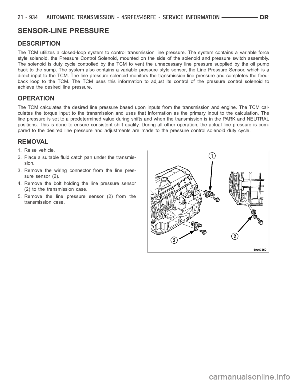
SENSOR-LINE PRESSURE
DESCRIPTION
The TCM utilizes a closed-loop system to control transmission line pressure. The system contains a variable force
style solenoid, the Pressure Control Solenoid, mounted on the side of the solenoid and pressure switch assembly.
The solenoid is duty cycle controlled by the TCM to vent the unnecessary line pressure supplied by the oil pump
back to the sump. The system also contains a variable pressure style sensor, the Line Pressure Sensor, which is a
direct input to the TCM. The line pressure solenoid monitors the transmission line pressure and completes the feed-
back loop to the TCM. The TCM uses this information to adjust its control of the pressure control solenoid to
achieve the desired line pressure.
OPERATION
The TCM calculates the desired line pressure based upon inputs from the transmission and engine. The TCM cal-
culates the torque input to the transmission and uses that information as the primary input to the calculation. The
line pressure is set to a predetermined value during shifts and when the transmission is in the PARK and NEUTRAL
positions. This is done to ensure consistent shift quality. During all other operation, the actual line pressure is com-
pared to the desired line pressure and adjustments are made to the pressurecontrol solenoid duty cycle.
REMOVAL
1. Raise vehicle.
2. Place a suitable fluid catch pan under the transmis-
sion.
3. Remove the wiring connector from the line pres-
sure sensor (2).
4. Remove the bolt holding the line pressure sensor
(2) to the transmission case.
5. Remove the line pressure sensor (2) from the
transmission case.