Page 3527 of 5267

11 .CHECK THE POWERTRAIN CONTROL MODULE
Reconnect all disconnected connectors.
Ignition on, engine not running.
With the scan tool, erase Engine DTCs.
Turn the ignition off to the lock position.
Disconnect the Governor Pressure Sensor connector internal to the
transmission.
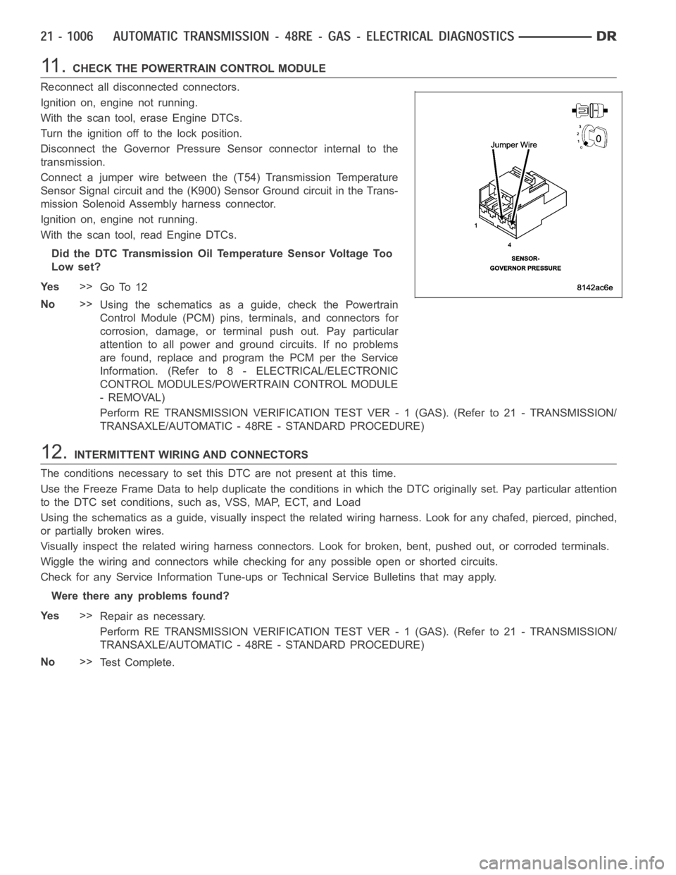
Connect a jumper wire between the (T54) Transmission Temperature
Sensor Signal circuit and the (K900) Sensor Ground circuit in the Trans-
mission Solenoid Assembly harness connector.
Ignition on, engine not running.
With the scan tool, read Engine DTCs.
Did the DTC Transmission Oil Temperature Sensor Voltage Too
Low set?
Ye s>>
Go To 12
No>>
Using the schematics as a guide, check the Powertrain
Control Module (PCM) pins, terminals, and connectors for
corrosion, damage, or terminal push out. Pay particular
attention to all power and ground circuits. If no problems
are found, replace and program the PCM per the Service
Information. (Refer to 8 - ELECTRICAL/ELECTRONIC
CONTROL MODULES/POWERTRAIN CONTROL MODULE
- REMOVAL)
Perform RE TRANSMISSION VERIFICATION TEST VER - 1 (GAS). (Refer to 21 - TRANSMISSION/
TRANSAXLE/AUTOMATIC - 48RE - STANDARD PROCEDURE)
12.INTERMITTENT WIRING AND CONNECTORS
The conditions necessary to set this DTC are not present at this time.
Use the Freeze Frame Data to help duplicate the conditions in which the DTC originally set. Pay particular attention
to the DTC set conditions, such as, VSS, MAP, ECT, and Load
Using the schematics as a guide, visually inspect the related wiring harness. Look for any chafed, pierced, pinched,
or partially broken wires.
Visually inspect the related wiring harness connectors. Look for broken,bent, pushed out, or corroded terminals.
Wiggle the wiring and connectors while checking for any possible open or shorted circuits.
Check for any Service Information Tune-ups or Technical Service Bulletins that may apply.
Were there any problems found?
Ye s>>
Repair as necessary.
Perform RE TRANSMISSION VERIFICATION TEST VER - 1 (GAS). (Refer to 21 - TRANSMISSION/
TRANSAXLE/AUTOMATIC - 48RE - STANDARD PROCEDURE)
No>>
Te s t C o m p l e t e .
Page 3528 of 5267
P0720-LOW OUTPUT SPEED SENSOR - RPM ABOVE 15 MPH (GAS)
For a complete wiring diagramRefer to Section 8W
Page 3533 of 5267

10.CHECK THE OUTPUT SPEED SENSOR
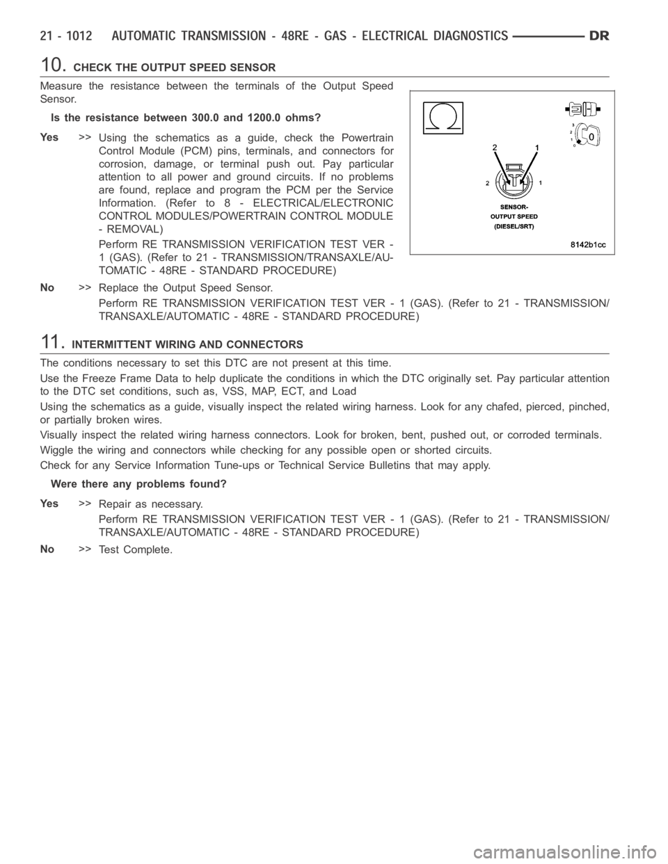
Measure the resistance between the terminals of the Output Speed
Sensor.
Is the resistance between 300.0 and 1200.0 ohms?
Ye s>>
Using the schematics as a guide, check the Powertrain
Control Module (PCM) pins, terminals, and connectors for
corrosion, damage, or terminal push out. Pay particular
attention to all power and ground circuits. If no problems
are found, replace and program the PCM per the Service
Information. (Refer to 8 - ELECTRICAL/ELECTRONIC
CONTROL MODULES/POWERTRAIN CONTROL MODULE
- REMOVAL)
Perform RE TRANSMISSION VERIFICATION TEST VER -
1 (GAS). (Refer to 21 - TRANSMISSION/TRANSAXLE/AU-
TOMATIC - 48RE - STANDARD PROCEDURE)
No>>
Replace the Output Speed Sensor.
Perform RE TRANSMISSION VERIFICATION TEST VER - 1 (GAS). (Refer to 21 - TRANSMISSION/
TRANSAXLE/AUTOMATIC - 48RE - STANDARD PROCEDURE)
11 .INTERMITTENT WIRING AND CONNECTORS
The conditions necessary to set this DTC are not present at this time.
Use the Freeze Frame Data to help duplicate the conditions in which the DTC originally set. Pay particular attention
to the DTC set conditions, such as, VSS, MAP, ECT, and Load
Using the schematics as a guide, visually inspect the related wiring harness. Look for any chafed, pierced, pinched,
or partially broken wires.
Visually inspect the related wiring harness connectors. Look for broken,bent, pushed out, or corroded terminals.
Wiggle the wiring and connectors while checking for any possible open or shorted circuits.
Check for any Service Information Tune-ups or Technical Service Bulletins that may apply.
Were there any problems found?
Ye s>>
Repair as necessary.
Perform RE TRANSMISSION VERIFICATION TEST VER - 1 (GAS). (Refer to 21 - TRANSMISSION/
TRANSAXLE/AUTOMATIC - 48RE - STANDARD PROCEDURE)
No>>
Te s t C o m p l e t e .
Page 3534 of 5267
P0740-TORQ CON CLU, NO RPM DROP AT LOCKUP (GAS)
For a complete wiring diagramRefer to Section 8W
Page 3537 of 5267

8.TCC SOLENOID
Turn the ignition off to the lock position.
Replace the TCC Solenoid per the Service Information (Refer to 21 - TRANSMISSION/TRANSAXLE/AUTOMATIC -
48RE/GOVERNOR PRESSURE SENSOR - REMOVAL).
With the scan tool, perform the Gov and 3-4 Shift Valve System Test.
Follow the instructions on the screen.
Did the engine stall?
Ye s>>
Repair internal transmission as necessary. Check for blocked or cross linkedpassagesintheValve
Body. (Refer to 21 - TRANSMISSION/TRANSAXLE/AUTOMATIC - 48RE/VALVE BODY- REMOVAL)
Perform RE TRANSMISSION VERIFICATION TEST VER - 1 (DIESEL). (Refer to 21 - TRANSMISSION/
TRANSAXLE/AUTOMATIC - 48RE - STANDARD PROCEDURE)
No>>
Te s t C o m p l e t e .
Perform RE TRANSMISSION VERIFICATION TEST VER - 1 (DIESEL). (Refer to 21 - TRANSMISSION/
TRANSAXLE/AUTOMATIC - 48RE - STANDARD PROCEDURE)
9.INTERMITTENT WIRING AND CONNECTORS
The conditions necessary set this DTC are not present at this time.
Use the Freeze Frame Data to help duplicate the conditions that set the DTC.Pay particular attention to the DTC
set conditions, such as, VSS, MAP, ECT, and Load.
Visually inspect the related wiring harness. Look for any chafed, pierced, pinched, or partially broken wires.
Visually inspect the related wiring harness connectors. Look for broken,bent, pushed out, or corroded terminals.
Refer to any technical service bulletins that may apply.
Were there any problems found?
Ye s>>
Repair as necessary.
Perform RE TRANSMISSION VERIFICATION TEST VER - 1 (DIESEL). (Refer to 21 - TRANSMISSION/
TRANSAXLE/AUTOMATIC - 48RE - STANDARD PROCEDURE)
No>>
Te s t C o m p l e t e .
Page 3538 of 5267
P0743-TORQUE CONVERTER CLUTCH SOLENOID/TRANS RELAY CIRCUITS
For a complete wiring diagramRefer to Section 8W
Page 3540 of 5267

3.CHECK THE (T16) TRANSMISSION CONTROL OUTPUT CIRCUIT
Ignition on, engine not running.
With the scan tool, actuate the Transmission Control Output in the
PCM.
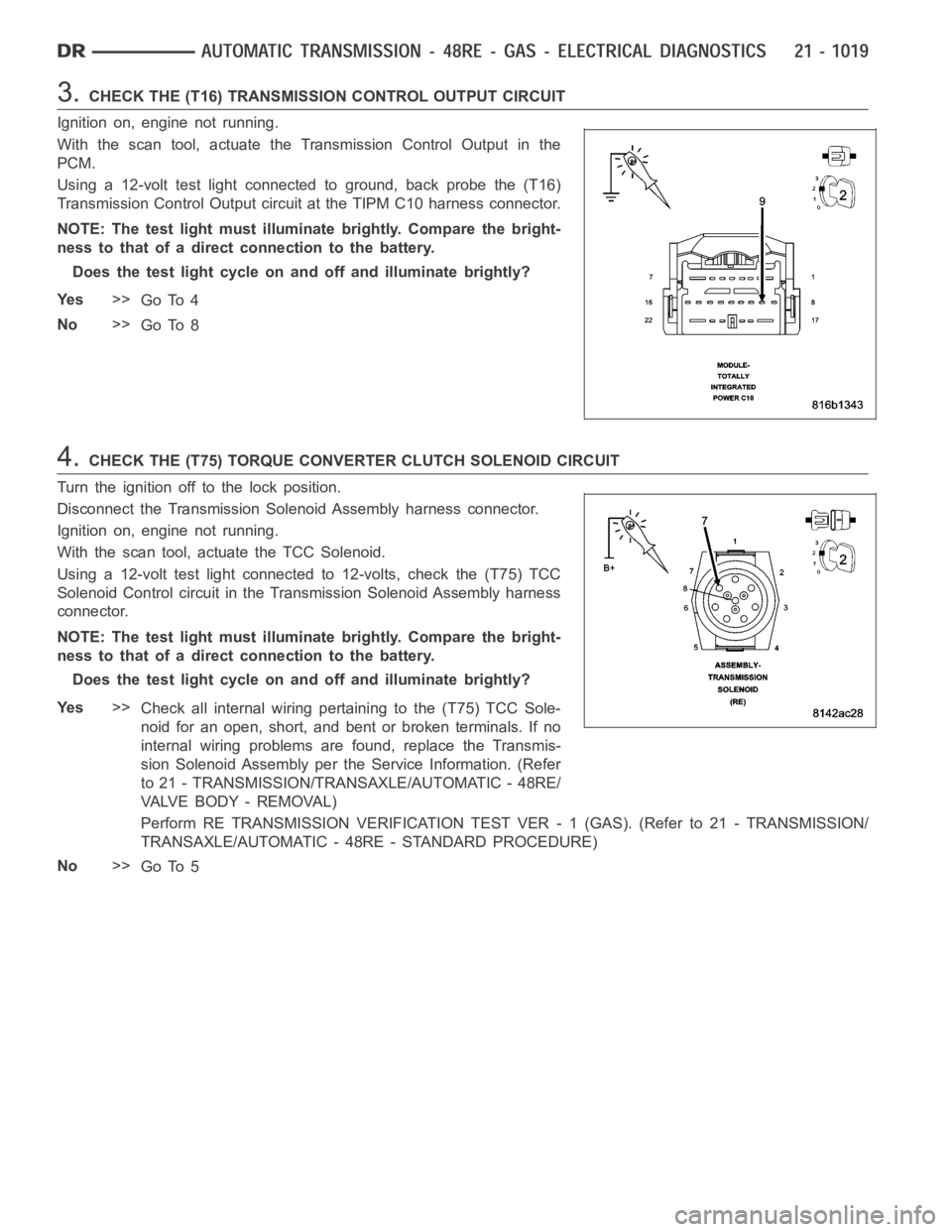
Using a 12-volt test light connected to ground, back probe the (T16)
Transmission Control Output circuit at the TIPM C10 harness connector.
NOTE: The test light must illuminate brightly. Compare the bright-
ness to that of a direct connection to the battery.
Does the test light cycle on and off and illuminate brightly?
Ye s>>
Go To 4
No>>
Go To 8
4.CHECK THE (T75) TORQUE CONVERTER CLUTCH SOLENOID CIRCUIT
Turn the ignition off to the lock position.
Disconnect the Transmission Solenoid Assembly harness connector.
Ignition on, engine not running.
With the scan tool, actuate the TCC Solenoid.
Using a 12-volt test light connected to 12-volts, check the (T75) TCC
Solenoid Control circuit in the Transmission Solenoid Assembly harness
connector.
NOTE: The test light must illuminate brightly. Compare the bright-
ness to that of a direct connection to the battery.
Does the test light cycle on and off and illuminate brightly?
Ye s>>
Check all internal wiring pertaining to the (T75) TCC Sole-
noid for an open, short, and bent or broken terminals. If no
internal wiring problems are found, replace the Transmis-
sion Solenoid Assembly per the Service Information. (Refer
to 21 - TRANSMISSION/TRANSAXLE/AUTOMATIC - 48RE/
VA LV E B O D Y - R E M O VA L )
Perform RE TRANSMISSION VERIFICATION TEST VER - 1 (GAS). (Refer to 21 - TRANSMISSION/
TRANSAXLE/AUTOMATIC - 48RE - STANDARD PROCEDURE)
No>>
Go To 5
Page 3544 of 5267
11 .INTERMITTENT WIRING AND CONNECTORS
The conditions necessary set this DTC are not present at this time.
Use the Freeze Frame Data to help duplicate the conditions that set the DTC.Pay particular attention to the DTC
set conditions, such as, VSS, MAP, ECT, and Load.
Visually inspect the related wiring harness. Look for any chafed, pierced, pinched, or partially broken wires.
Visually inspect the related wiring harness connectors. Look for broken,bent, pushed out, or corroded terminals.
Refer to any technical service bulletins that may apply.
Were there any problems found?
Ye s>>
Repair as necessary.
Perform RE TRANSMISSION VERIFICATION TEST VER - 1 (GAS). (Refer to 21 - TRANSMISSION/
TRANSAXLE/AUTOMATIC - 48RE - STANDARD PROCEDURE)
No>>
Te s t C o m p l e t e .