Page 4878 of 5267
B10BF–CONDENSER FAN CONTROL CIRCUIT HIGH (TIPM)
For a complete wiring diagramRefer to Section 8W.
Page 4881 of 5267

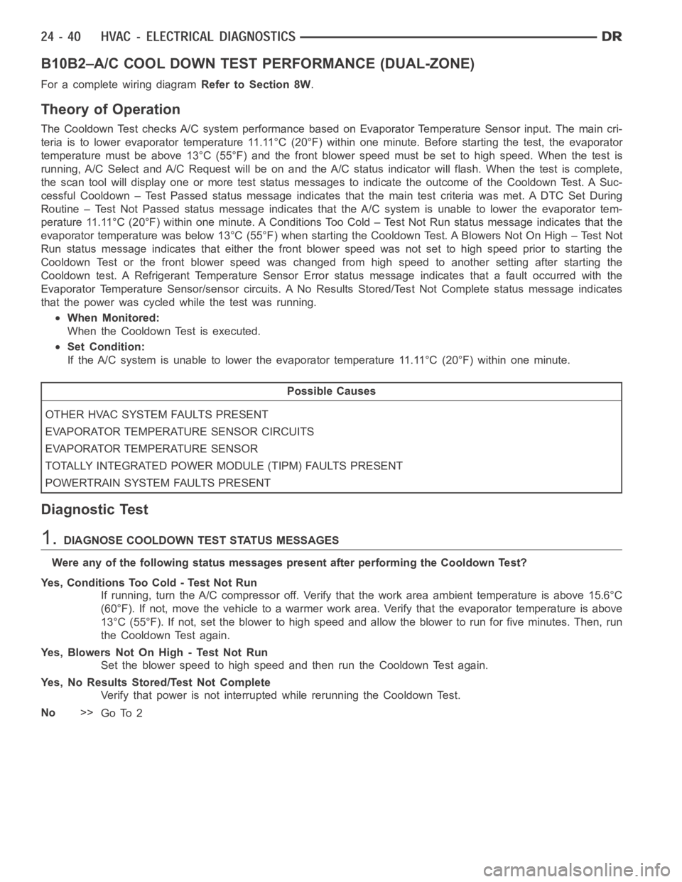
B10B2–A/C COOL DOWN TEST PERFORMANCE (DUAL-ZONE)
For a complete wiring diagramRefer to Section 8W.
Theory of Operation
The Cooldown Test checks A/C system performance based on Evaporator Temperature Sensor input. The main cri-
teria is to lower evaporator temperature 11.11°C (20°F) within one minute. Before starting the test, the evaporator
temperature must be above 13°C (55°F) and the front blower speed must be setto high speed. When the test is
running, A/C Select and A/C Request will be on and the A/C status indicator will flash. When the test is complete,
the scan tool will display one or more test status messages to indicate the outcome of the Cooldown Test. A Suc-
cessful Cooldown – Test Passed status message indicates that the main testcriteria was met. A DTC Set During
Routine – Test Not Passed status message indicates that the A/C system is unable to lower the evaporator tem-
perature 11.11°C (20°F) within one minute. A Conditions Too Cold – Test NotRun status message indicates that the
evaporator temperature was below 13°C (55°F) when starting the Cooldown Test. A Blowers Not On High – Test Not
Run status message indicates that either the front blower speed was not setto high speed prior to starting the
Cooldown Test or the front blower speed was changed from high speed to another setting after starting the
Cooldown test. A Refrigerant Temperature Sensor Error status message indicates that a fault occurred with the
Evaporator Temperature Sensor/sensor circuits. A No Results Stored/Test Not Complete status message indicates
that the power was cycled while the test was running.
When Monitored:
When the Cooldown Test is executed.
Set Condition:
If the A/C system is unable to lower the evaporator temperature 11.11°C (20°F) within one minute.
Possible Causes
OTHER HVAC SYSTEM FAULTS PRESENT
EVAPORATOR TEMPERATURE SENSOR CIRCUITS
EVAPORATOR TEMPERATURE SENSOR
TOTALLY INTEGRATED POWER MODULE (TIPM) FAULTS PRESENT
POWERTRAIN SYSTEM FAULTS PRESENT
Diagnostic Test
1.DIAGNOSE COOLDOWN TEST STATUS MESSAGES
WereanyofthefollowingstatusmessagespresentafterperformingtheCooldown Test?
Yes, Conditions Too Cold - Test Not Run
If running, turn the A/C compressor off. Verify that the work area ambient temperature is above 15.6°C
(60°F). If not, move the vehicle to a warmer work area. Verify that the evaporator temperature is above
13°C (55°F). If not, set the blower to high speed and allow the blower to run for five minutes. Then, run
the Cooldown Test again.
Yes, Blowers Not On High - Test Not Run
Set the blower speed to high speed and then run the Cooldown Test again.
Yes, No Results Stored/Test Not Complete
Verify that power is not interrupted while rerunning the Cooldown Test.
No>>
Go To 2
Page 4883 of 5267
B10C0–CONDENSER FAN CONTROL CIRCUIT OPEN (TIPM)
For a complete wiring diagramRefer to Section 8W.
Page 4886 of 5267
B10EC–BLOWER MOTOR CONTROL CIRCUIT OVERCURRENT (TIPM)
For a complete wiring diagramRefer to Section 8W
Page 4891 of 5267
B10EE–CONDENSER FAN CONTROLCIRCUIT OVERCURRENT (TIPM)
For a complete wiring diagramRefer to Section 8W.
Page 4895 of 5267
B10E9–BLOWER MOTOR CONTROL CIRCUIT LOW (TIPM)
For a complete wiring diagramRefer to Section 8W.
Page 4898 of 5267

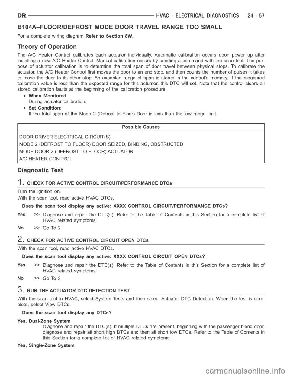
B104A–FLOOR/DEFROST MODEDOOR TRAVEL RANGE TOO SMALL
For a complete wiring diagramRefer to Section 8W.
Theory of Operation
The A/C Heater Control calibrates each actuator individually. Automaticcalibration occurs upon power up after
installing a new A/C Heater Control. Manual calibration occurs by sendinga command with the scan tool. The pur-
pose of actuator calibration is to determine the total span of door travel between physical stops. To calibrate the
actuator, the A/C Heater Control first moves the door to an end stop, and then counts the number of pulses it takes
to move the door to its other stop. An expected range of span is stored in the control’s memory. If the measured
calibration value is less than the expected range for this actuator, this DTC will set. Note thatthe control clears all
stored calibration faults at the beginning of the calibration procedure.
When Monitored:
During actuator calibration.
Set Condition:
If the total span of the Mode 2 (Defrost to Floor) Door is less than the low range limit.
Possible Causes
DOOR DRIVER ELECTRICAL CIRCUIT(S)
MODE 2 (DEFROST TO FLOOR) DOOR SEIZED, BINDING, OBSTRUCTED
MODE DOOR 2 (DEFROST TO FLOOR) ACTUATOR
A/C HEATER CONTROL
Diagnostic Test
1.CHECK FOR ACTIVE CONTROL CIRCUIT/PERFORMANCE DTCs
Turn the ignition on.
With the scan tool, read active HVAC DTCs.
Does the scan tool display any active: XXXX CONTROL CIRCUIT/PERFORMANCE DTCs?
Ye s>>
Diagnose and repair the DTC(s). Refer to the Table of Contents in this Section for a complete list of
HVAC related symptoms.
No>>
Go To 2
2.CHECK FOR ACTIVE CONTROL CIRCUIT OPEN DTCs
With the scan tool, read active HVAC DTCs.
Does the scan tool display any active: XXXX CONTROL CIRCUIT OPEN DTCs?
Ye s>>
Diagnose and repair the DTC(s). Refer to the Table of Contents in this Section for a complete list of
HVAC related symptoms.
No>>
Go To 3
3.RUN THE ACTUATOR DTC DETECTION TEST
With the scan tool in HVAC, select System Tests and then select Actuator DTCDetection. When the test is com-
plete, select View DTCs.
Does the scan tool display any DTCs?
Yes, Dual-Zone System
Diagnose and repair the DTC(s). If multiple DTCs are present, beginning with the passenger blend door,
diagnose and repair all short high DTCs and then all short low DTCs. Refer tothe Table of Contents in
this Section for a complete list of HVAC related symptoms.
Yes, Single-Zone System
Page 4900 of 5267

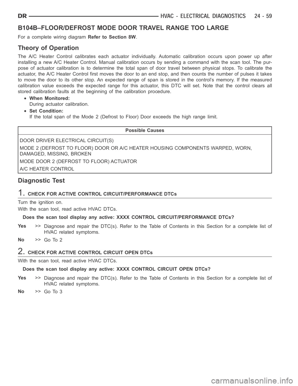
B104B–FLOOR/DEFROST MODEDOOR TRAVEL RANGE TOO LARGE
For a complete wiring diagramRefer to Section 8W.
Theory of Operation
The A/C Heater Control calibrates each actuator individually. Automaticcalibration occurs upon power up after
installing a new A/C Heater Control. Manual calibration occurs by sendinga command with the scan tool. The pur-
pose of actuator calibration is to determine the total span of door travel between physical stops. To calibrate the
actuator, the A/C Heater Control first moves the door to an end stop, and then counts the number of pulses it takes
to move the door to its other stop. An expected range of span is stored in the control’s memory. If the measured
calibration value exceeds the expected range for this actuator, this DTC will set. Note that the control clears all
stored calibration faults at the beginning of the calibration procedure.
When Monitored:
During actuator calibration.
Set Condition:
If the total span of the Mode 2 (Defrost to Floor) Door exceeds the high rangelimit.
Possible Causes
DOOR DRIVER ELECTRICAL CIRCUIT(S)
MODE 2 (DEFROST TO FLOOR) DOOR OR A/C HEATER HOUSING COMPONENTS WARPED, WORN,
DAMAGED, MISSING, BROKEN
MODE DOOR 2 (DEFROST TO FLOOR) ACTUATOR
A/C HEATER CONTROL
Diagnostic Test
1.CHECK FOR ACTIVE CONTROL CIRCUIT/PERFORMANCE DTCs
Turn the ignition on.
With the scan tool, read active HVAC DTCs.
Does the scan tool display any active: XXXX CONTROL CIRCUIT/PERFORMANCE DTCs?
Ye s>>
Diagnose and repair the DTC(s). Refer to the Table of Contents in this Section for a complete list of
HVAC related symptoms.
No>>
Go To 2
2.CHECK FOR ACTIVE CONTROL CIRCUIT OPEN DTCs
With the scan tool, read active HVAC DTCs.
Does the scan tool display any active: XXXX CONTROL CIRCUIT OPEN DTCs?
Ye s>>
Diagnose and repair the DTC(s). Refer to the Table of Contents in this Section for a complete list of
HVAC related symptoms.
No>>
Go To 3