Page 4959 of 5267

4.CHECK (C29) MODE DOOR 1 DRIVER CIRCUIT FOR A SHORT TO (C34) COMMON DOOR DRIVER
CIRCUIT
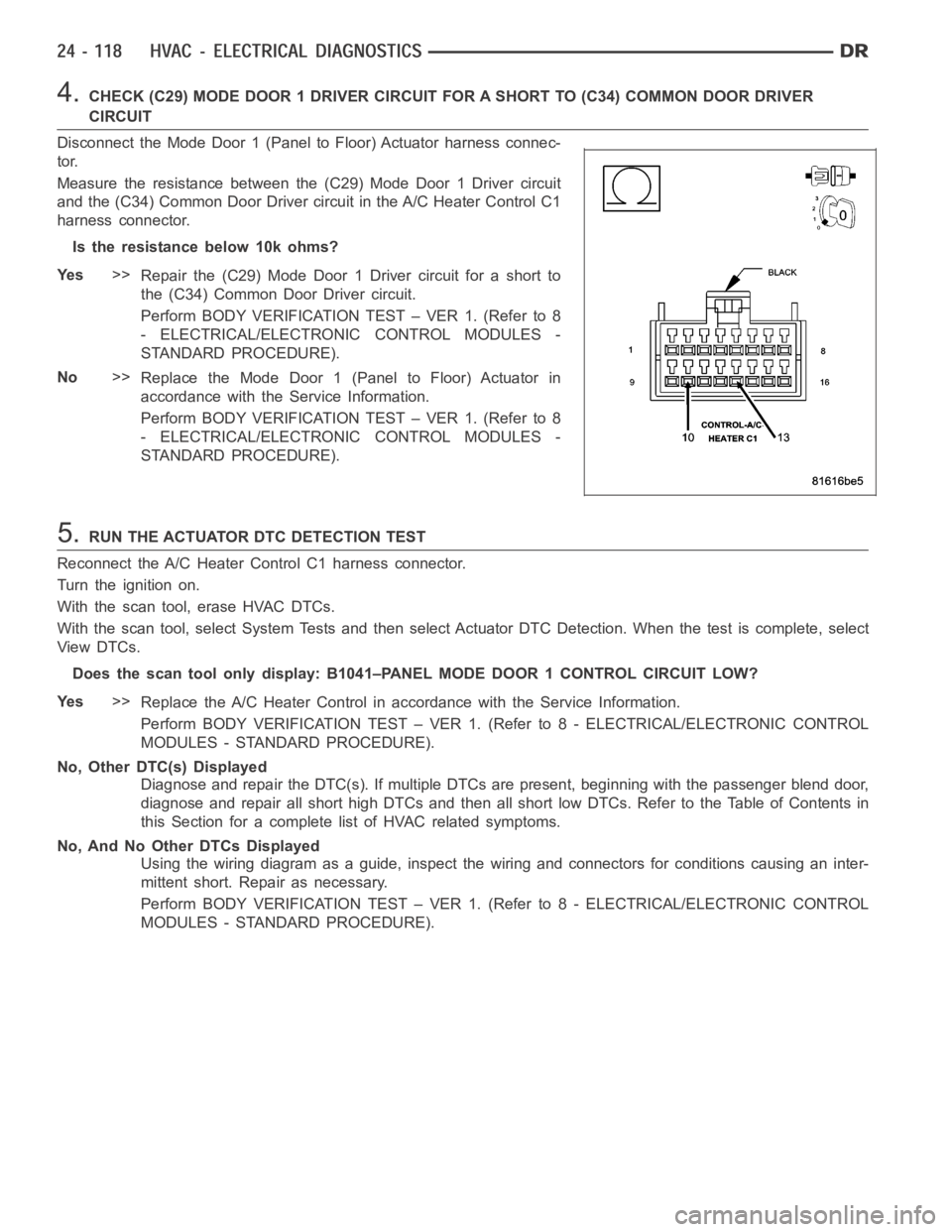
Disconnect the Mode Door 1 (Panel to Floor) Actuator harness connec-
tor.
Measure the resistance between the (C29) Mode Door 1 Driver circuit
and the (C34) Common Door Driver circuit in the A/C Heater Control C1
harness connector.
Istheresistancebelow10kohms?
Ye s>>
Repair the (C29) Mode Door 1 Driver circuit for a short to
the (C34) Common Door Driver circuit.
Perform BODY VERIFICATION TEST – VER 1. (Refer to 8
- ELECTRICAL/ELECTRONIC CONTROL MODULES -
STANDARD PROCEDURE).
No>>
Replace the Mode Door 1 (Panel to Floor) Actuator in
accordance with the Service Information.
Perform BODY VERIFICATION TEST – VER 1. (Refer to 8
- ELECTRICAL/ELECTRONIC CONTROL MODULES -
STANDARD PROCEDURE).
5.RUN THE ACTUATOR DTC DETECTION TEST
Reconnect the A/C Heater Control C1 harness connector.
Turn the ignition on.
With the scan tool, erase HVAC DTCs.
With the scan tool, select System Tests and then select Actuator DTC Detection. When the test is complete, select
View DTCs.
Does the scan tool only display: B1041–PANEL MODE DOOR 1 CONTROL CIRCUIT LOW?
Ye s>>
Replace the A/C Heater Control in accordance with the Service Information.
Perform BODY VERIFICATION TEST – VER 1. (Refer to 8 - ELECTRICAL/ELECTRONIC CONTROL
MODULES - STANDARD PROCEDURE).
No, Other DTC(s) Displayed
Diagnose and repair the DTC(s). If multiple DTCs are present, beginning with the passenger blend door,
diagnose and repair all short high DTCs and then all short low DTCs. Refer tothe Table of Contents in
this Section for a complete list of HVAC related symptoms.
No, And No Other DTCs Displayed
Using the wiring diagram as a guide, inspect the wiring and connectors for conditions causing an inter-
mittent short. Repair as necessary.
Perform BODY VERIFICATION TEST – VER 1. (Refer to 8 - ELECTRICAL/ELECTRONIC CONTROL
MODULES - STANDARD PROCEDURE).
Page 4960 of 5267
B1041–PANEL MODE DOOR 1 CONTROL CIRCUIT LOW (SINGLE-ZONE)
For a complete wiring diagramRefer to Section 8W.
Page 4963 of 5267

4.CHECK (C29) MODE DOOR 1 DRIVER CIRCUIT FOR A SHORT TO (C34) COMMON DOOR DRIVER
CIRCUIT
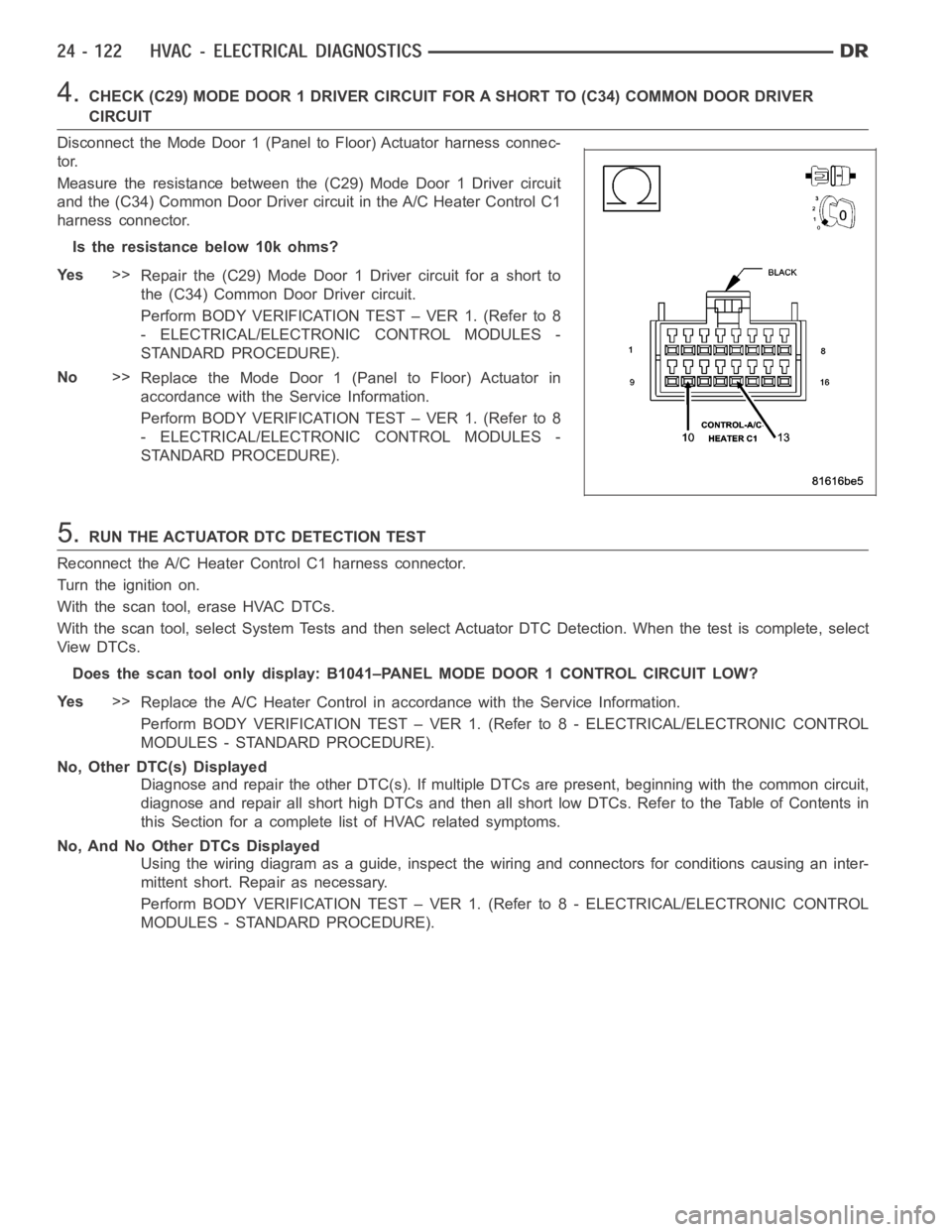
Disconnect the Mode Door 1 (Panel to Floor) Actuator harness connec-
tor.
Measure the resistance between the (C29) Mode Door 1 Driver circuit
and the (C34) Common Door Driver circuit in the A/C Heater Control C1
harness connector.
Istheresistancebelow10kohms?
Ye s>>
Repair the (C29) Mode Door 1 Driver circuit for a short to
the (C34) Common Door Driver circuit.
Perform BODY VERIFICATION TEST – VER 1. (Refer to 8
- ELECTRICAL/ELECTRONIC CONTROL MODULES -
STANDARD PROCEDURE).
No>>
Replace the Mode Door 1 (Panel to Floor) Actuator in
accordance with the Service Information.
Perform BODY VERIFICATION TEST – VER 1. (Refer to 8
- ELECTRICAL/ELECTRONIC CONTROL MODULES -
STANDARD PROCEDURE).
5.RUN THE ACTUATOR DTC DETECTION TEST
Reconnect the A/C Heater Control C1 harness connector.
Turn the ignition on.
With the scan tool, erase HVAC DTCs.
With the scan tool, select System Tests and then select Actuator DTC Detection. When the test is complete, select
View DTCs.
Does the scan tool only display: B1041–PANEL MODE DOOR 1 CONTROL CIRCUIT LOW?
Ye s>>
Replace the A/C Heater Control in accordance with the Service Information.
Perform BODY VERIFICATION TEST – VER 1. (Refer to 8 - ELECTRICAL/ELECTRONIC CONTROL
MODULES - STANDARD PROCEDURE).
No, Other DTC(s) Displayed
Diagnose and repair the other DTC(s). If multiple DTCs are present, beginning with the common circuit,
diagnose and repair all short high DTCs and then all short low DTCs. Refer tothe Table of Contents in
this Section for a complete list of HVAC related symptoms.
No, And No Other DTCs Displayed
Using the wiring diagram as a guide, inspect the wiring and connectors for conditions causing an inter-
mittent short. Repair as necessary.
Perform BODY VERIFICATION TEST – VER 1. (Refer to 8 - ELECTRICAL/ELECTRONIC CONTROL
MODULES - STANDARD PROCEDURE).
Page 4964 of 5267
B1042–PANEL MODE DOOR 1 CONTROL CIRCUIT HIGH (DUAL-ZONE)
For a complete wiring diagramRefer to Section 8W.
Page 4966 of 5267
Diagnose and repair the DTC(s). If multiple DTCs are present, beginning with the passenger blend door,
diagnose and repair all short high DTCs and then all short low DTCs. Refer tothe Table of Contents in
this Section for a complete list of HVAC related symptoms.
No, And No Other DTCs Displayed
Using the wiring diagram as a guide, inspect the wiring and connectors for conditions causing an inter-
mittent short. Repair as necessary.
Perform BODY VERIFICATION TEST – VER 1. (Refer to 8 - ELECTRICAL/ELECTRONIC CONTROL
MODULES - STANDARD PROCEDURE).
Page 4967 of 5267
B1042–PANEL MODE DOOR 1 CONTROL CIRCUIT HIGH (SINGLE-ZONE)
For a complete wiring diagramRefer to Section 8W.
Page 4969 of 5267
Diagnose and repair the other DTC(s). If multiple DTCs are present, beginning with the common circuit,
diagnose and repair all short high DTCs and then all short low DTCs. Refer tothe Table of Contents in
this Section for a complete list of HVAC related symptoms.
No, And No Other DTCs Displayed
Using the wiring diagram as a guide, inspect the wiring and connectors for conditions causing an inter-
mittent short. Repair as necessary.
Perform BODY VERIFICATION TEST – VER 1. (Refer to 8 - ELECTRICAL/ELECTRONIC CONTROL
MODULES - STANDARD PROCEDURE).
Page 4970 of 5267
B1043–PANEL MODE DOOR 1 CONTROL CIRCUIT OPEN (DUAL-ZONE)
For a complete wiring diagramRefer to Section 8W.