Page 3362 of 5267

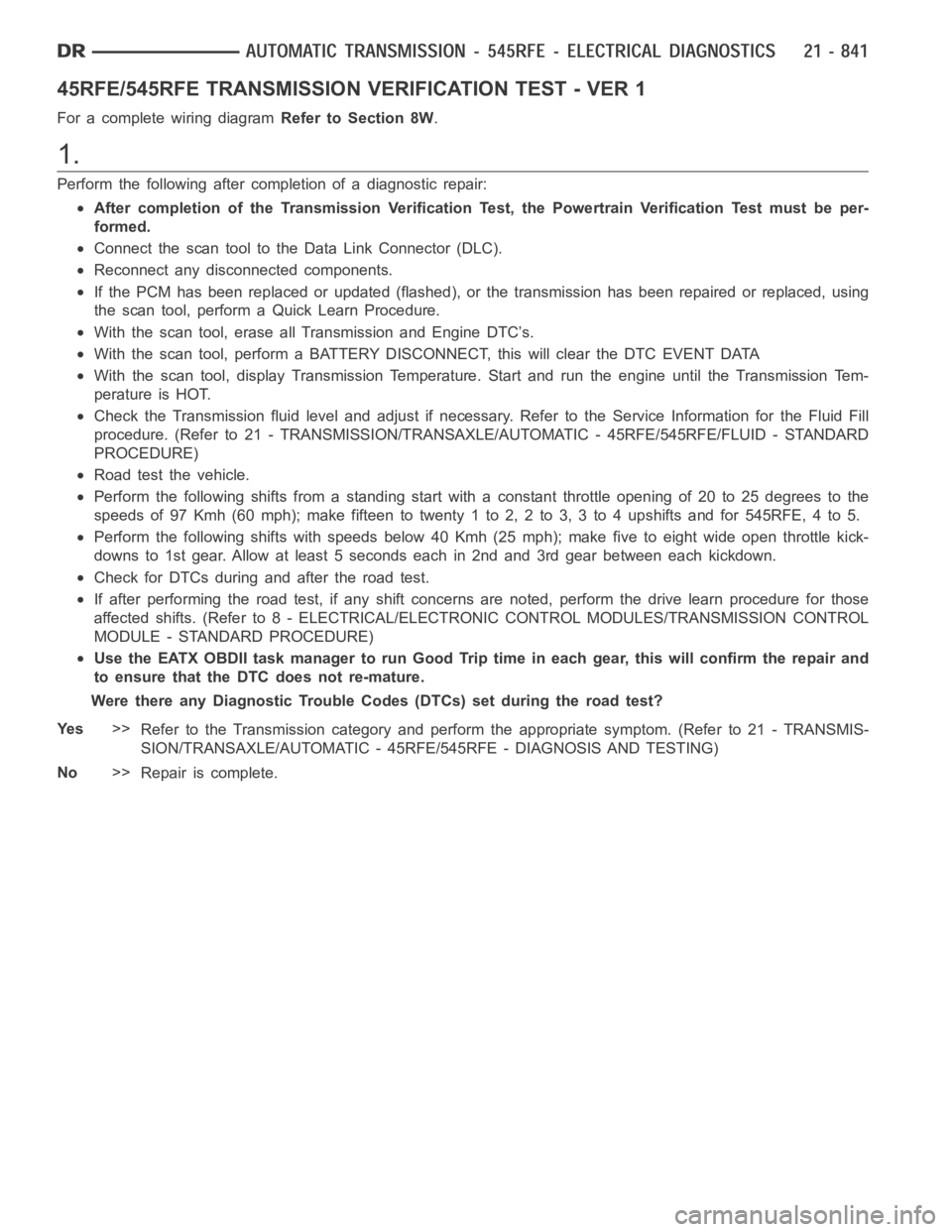
45RFE/545RFE TRANSMISSION VERIFICATION TEST - VER 1
For a complete wiring diagramRefer to Section 8W.
1.
Perform the following after completion of a diagnostic repair:
After completion of the Transmission Verification Test, the Powertrain Verification Test must be per-
formed.
Connect the scan tool to the Data Link Connector (DLC).
Reconnect any disconnected components.
If the PCM has been replaced or updated (flashed), or the transmission has been repaired or replaced, using
the scan tool, perform a Quick Learn Procedure.
With the scan tool, erase all Transmission and Engine DTC’s.
With the scan tool, perform a BATTERY DISCONNECT, this will clear the DTC EVENT DATA
With the scan tool, display Transmission Temperature. Start and run the engine until the Transmission Tem-
perature is HOT.
Check the Transmission fluid level and adjust if necessary. Refer to the Service Information for the Fluid Fill
procedure. (Refer to 21 - TRANSMISSION/TRANSAXLE/AUTOMATIC - 45RFE/545RFE/FLUID - STANDARD
PROCEDURE)
Road test the vehicle.
Perform the following shifts from a standing start with a constant throttle opening of 20 to 25 degrees to the
speeds of 97 Kmh (60 mph); make fifteen to twenty 1 to 2, 2 to 3, 3 to 4 upshifts andfor545RFE,4to5.
Perform the following shifts with speeds below 40 Kmh (25 mph); make five toeight wide open throttle kick-
downs to 1st gear. Allow at least 5 seconds each in 2nd and 3rd gear between each kickdown.
Check for DTCs during and after the road test.
If after performing the road test, if any shift concerns are noted, performthe drive learn procedure for those
affected shifts. (Refer to 8 - ELECTRICAL/ELECTRONIC CONTROL MODULES/TRANSMISSION CONTROL
MODULE - STANDARD PROCEDURE)
Use the EATX OBDII task manager to run Good Trip time in each gear, this will confirm the repair and
to ensure that the DTC does not re-mature.
Were there any Diagnostic Trouble Codes (DTCs) set during the road test?
Ye s>>
Refer to the Transmission category and perform the appropriate symptom. (Refer to 21 - TRANSMIS-
SION/TRANSAXLE/AUTOMATIC - 45RFE/545RFE - DIAGNOSIS AND TESTING)
No>>
Repair is complete.
Page 3363 of 5267

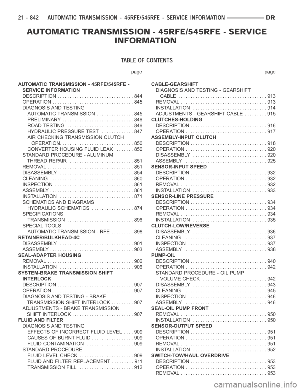
page page
AUTOMATIC TRANSMISSION - 45RFE/545RFE -
SERVICE INFORMATION
DESCRIPTION ............................... 844
OPERATION ................................. 845
DIAGNOSIS AND TESTING
AUTOMATIC TRANSMISSION ............... 845
PRELIMINARY ............................. 846
ROAD TESTING ........................... 846
HYDRAULIC PRESSURE TEST............. 847
AIR CHECKING TRANSMISSION CLUTCH
OPERATION............................... 850
CONVERTER HOUSING FLUID LEAK ....... 850
STANDARD PROCEDURE - ALUMINUM
THREAD REPAIR .......................... 851
REMOVAL ................................... 851
DISASSEMBLY .............................. 854
CLEANING .................................. 860
INSPECTION ................................ 861
ASSEMBLY .................................. 861
INSTALLATION .............................. 871
SCHEMATICS AND DIAGRAMS
HYDRAULIC SCHEMATICS ................. 874
SPECIFICATIONS
TRANSMISSION ........................... 896
SPECIAL TOOLS
AUTOMATIC TRANSMISSION - RFE ......... 898
RETAINER/BULKHEAD-4C
DISASSEMBLY .............................. 901
ASSEMBLY .................................. 903
SEAL-ADAPTER HOUSING
REMOVAL ................................... 906
INSTALLATION .............................. 906
SYSTEM-BRAKE TRANSMISSION SHIFT
INTERLOCK
DESCRIPTION ............................... 907
OPERATION ................................. 907
DIAGNOSIS AND TESTING - BRAKE
TRANSMISSION SHIFT INTERLOCK ......... 907
ADJUSTMENTS - BRAKE TRANSMISSION
SHIFT INTERLOCK ......................... 907
FLUID AND FILTER
DIAGNOSIS AND TESTING
EFFECTS OF INCORRECT FLUID LEVEL.... 909
CAUSES OF BURNT FLUID ................. 909
FLUID CONTAMINATION ................... 909
STANDARD PROCEDURE
FLUID LEVEL CHECK . ..................... 909
FLUID AND FILTER REPLACEMENT ......... 911
TRANSMISSION FILL ...................... 912CABLE-GEARSHIFT
DIAGNOSIS AND TESTING - GEARSHIFT
CABLE .................................... 913
REMOVAL ................................... 913
INSTALLATION .............................. 914
ADJUSTMENTS - GEARSHIFT CABLE ......... 915
CLUTCHES-HOLDING
DESCRIPTION ............................... 916
OPERATION ................................. 917
ASSEMBLY-INPUT CLUTCH
DESCRIPTION ............................... 918
OPERATION ................................. 920
DISASSEMBLY .............................. 920
ASSEMBLY .................................. 925
SENSOR-INPUT SPEED
DESCRIPTION ............................... 932
OPERATION ................................. 932
REMOVAL ................................... 932
INSTALLATION .............................. 933
SENSOR-LINE PRESSURE
DESCRIPTION ............................... 934
OPERATION ................................. 934
REMOVAL ................................... 934
INSTALLATION .............................. 935
CLUTCH-LOW/REVERSE
DISASSEMBLY .............................. 936
CLEANING .................................. 937
INSPECTION . . .............................. 937
ASSEMBLY .................................. 938
PUMP-OIL
DESCRIPTION ............................... 940
OPERATION ................................. 942
STANDARD PROCEDURE - OIL PUMP
VOLUME CHECK .......................... 942
DISASSEMBLY .............................. 943
CLEANING .................................. 945
INSPECTION . . .............................. 946
ASSEMBLY .................................. 946
SEAL-OIL PUMP FRONT
REMOVAL ................................... 950
INSTALLATION .............................. 950
SENSOR-OUTPUT SPEED
DESCRIPTION ............................... 951
OPERATION ................................. 951
REMOVAL ................................... 951
INSTALLATION .............................. 952
SWITCH-TOW/HAUL OVERDRIVE
DESCRIPTION ............................... 953
OPERATION ................................. 953
REMOVAL ................................... 953
Page 3395 of 5267
SCHEMATICS AND DIAGRAMS
HYDRAULIC SCHEMATICS
Page 3510 of 5267
P0711-TRANS TEMP SENSOR, NO TEMP RISE AFTER START (GAS)
For a complete wiring diagramRefer to Section 8W.
Page 3514 of 5267
P0712-TRANS TEMP SENSOR VOLTAGE TOO LOW (GAS)
For a complete wiring diagramRefer to Section 8W
Page 3520 of 5267
P0713-TRANS TEMP SENSOR VOLTAGE TOO HIGH (GAS)
For a complete wiring diagramRefer to Section 8W
Page 3528 of 5267
P0720-LOW OUTPUT SPEED SENSOR - RPM ABOVE 15 MPH (GAS)
For a complete wiring diagramRefer to Section 8W
Page 3534 of 5267
P0740-TORQ CON CLU, NO RPM DROP AT LOCKUP (GAS)
For a complete wiring diagramRefer to Section 8W