Page 3345 of 5267

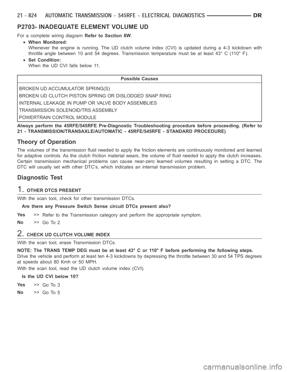
P2703- INADEQUATE ELEMENT VOLUME UD
For a complete wiring diagramRefer to Section 8W.
When Monitored:
Whenever the engine is running. The UD clutch volume index (CVI) is updatedduring a 4-3 kickdown with
throttle angle between 10 and 54 degrees. Transmission temperature must be at least 43° C (110° F).
Set Condition:
When the UD CVI falls below 11.
Possible Causes
BROKEN UD ACCUMULATOR SPRING(S)
BROKEN UD CLUTCH PISTON SPRING OR DISLODGED SNAP RING
INTERNAL LEAKAGE IN PUMP OR VALVE BODY ASSEMBLIES
TRANSMISSION SOLENOID/TRS ASSEMBLY
POWERTRAIN CONTROL MODULE
Always perform the 45RFE/545RFE Pre-Diagnostic Troubleshooting procedure before proceeding. (Refer to
21 - TRANSMISSION/TRANSAXLE/AUTOMATIC - 45RFE/545RFE - STANDARD PROCEDURE)
Theory of Operation
The volumes of the transmission fluid needed to apply the friction elements are continuously monitored and learned
for adaptive controls. As the clutch friction material wears, the volume of fluid needed to apply the clutch increases.
Certain transmission mechanical problems can cause near-zero learned volumes resulting in setting a DTC. The
DTC will usually set with other DTC’s, which indicates an internal transmission problem.
Diagnostic Test
1.OTHER DTCS PRESENT
With the scan tool, check for other transmission DTCs.
Are there any Pressure Switch Sense circuit DTCs present also?
Ye s>>
Refer to the Transmission category and perform the appropriate symptom.
No>>
Go To 2
2.CHECK UD CLUTCH VOLUME INDEX
With the scan tool, erase Transmission DTCs.
NOTE: The TRANS TEMP DEG must be at least 43° C or 110° F before performing thefollowing steps.
Drive the vehicle and perform at least ten 4-3 kickdowns by depressing the throttle between 30 and 54 TPS degrees
at speeds about 80 Kmh or 50 MPH.
With the scan tool, read the UD clutch volume index (CVI).
Is the UD CVI below 10?
Ye s>>
Go To 3
No>>
Go To 5
Page 3347 of 5267

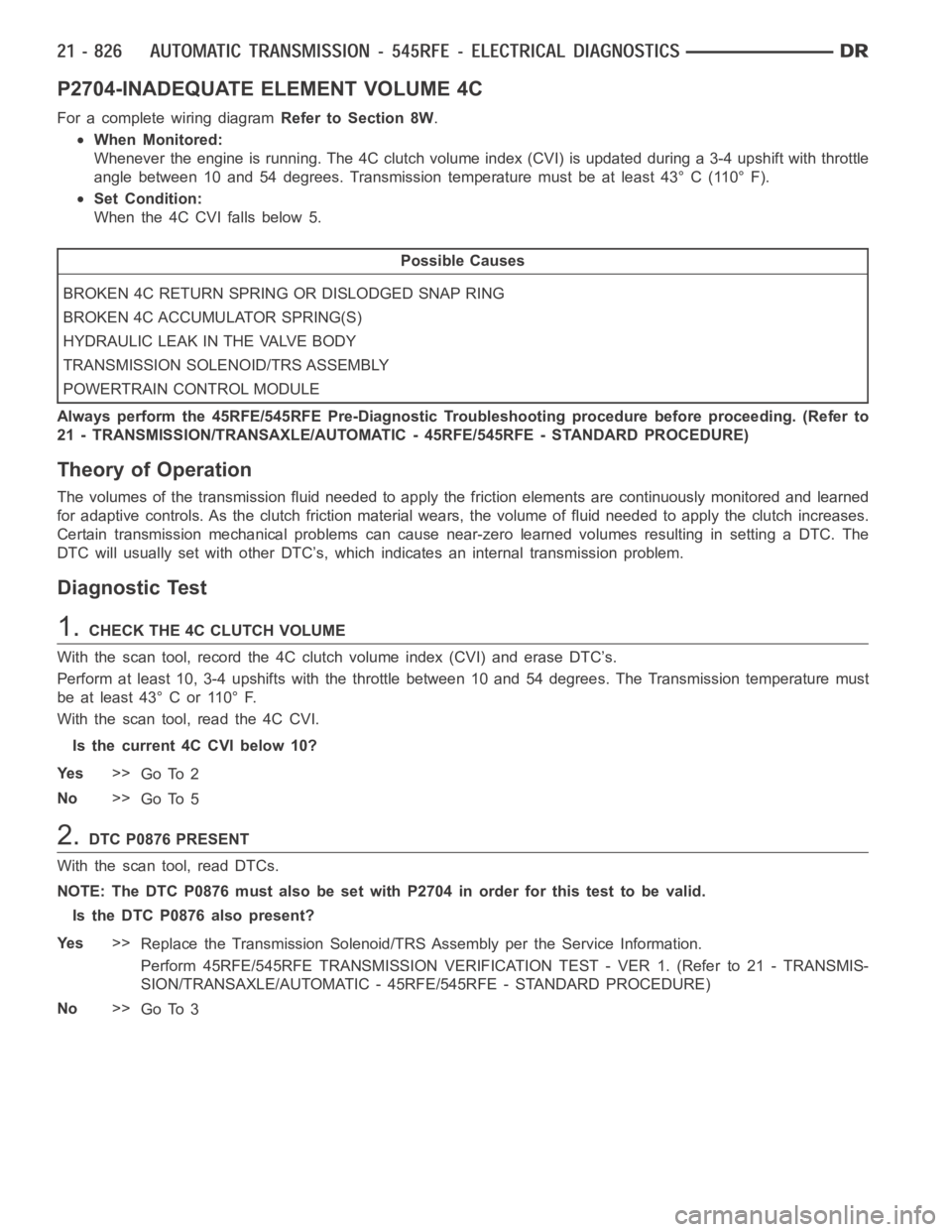
P2704-INADEQUATE ELEMENT VOLUME 4C
For a complete wiring diagramRefer to Section 8W.
When Monitored:
Whenever the engine is running. The 4C clutch volume index (CVI) is updatedduring a 3-4 upshift with throttle
angle between 10 and 54 degrees. Transmission temperature must be at least43° C (110° F).
Set Condition:
When the 4C CVI falls below 5.
Possible Causes
BROKEN 4C RETURN SPRING OR DISLODGED SNAP RING
BROKEN 4C ACCUMULATOR SPRING(S)
HYDRAULIC LEAK IN THE VALVE BODY
TRANSMISSION SOLENOID/TRS ASSEMBLY
POWERTRAIN CONTROL MODULE
Always perform the 45RFE/545RFE Pre-Diagnostic Troubleshooting procedure before proceeding. (Refer to
21 - TRANSMISSION/TRANSAXLE/AUTOMATIC - 45RFE/545RFE - STANDARD PROCEDURE)
Theory of Operation
The volumes of the transmission fluid needed to apply the friction elements are continuously monitored and learned
for adaptive controls. As the clutch friction material wears, the volume of fluid needed to apply the clutch increases.
Certain transmission mechanical problems can cause near-zero learned volumes resulting in setting a DTC. The
DTC will usually set with other DTC’s, which indicates an internal transmission problem.
Diagnostic Test
1.CHECK THE 4C CLUTCH VOLUME
With the scan tool, record the 4C clutch volume index (CVI) and erase DTC’s.
Perform at least 10, 3-4 upshifts with the throttle between 10 and 54 degrees. The Transmission temperature must
be at least 43° C or 110° F.
With the scan tool, read the 4C CVI.
Is the current 4C CVI below 10?
Ye s>>
Go To 2
No>>
Go To 5
2.DTC P0876 PRESENT
With the scan tool, read DTCs.
NOTE: The DTC P0876 must also be set with P2704 in order for this test to be valid.
Is the DTC P0876 also present?
Ye s>>
Replace the Transmission Solenoid/TRS Assembly per the Service Information.
Perform 45RFE/545RFE TRANSMISSION VERIFICATION TEST - VER 1. (Refer to 21- TRANSMIS-
SION/TRANSAXLE/AUTOMATIC - 45RFE/545RFE - STANDARD PROCEDURE)
No>>
Go To 3
Page 3349 of 5267
P2706-MS SOLENOID CIRCUIT
For a complete wiring diagramRefer to Section 8W.
Page 3353 of 5267
U0002-CAN C BUS OFF PERFORMANCE
For a complete wiring diagramRefer to Section 8W.
Page 3355 of 5267
U0100-NO COMMUNICATION WITH THE ECM/PCM
For a complete wiring diagramRefer to Section 8W.
Page 3357 of 5267
U0121-LOST COMMUNICATION WITH ABS
For a complete wiring diagramRefer to Section 8W.
Page 3359 of 5267
U0141 LOST COMMUNICATION WITH FCM
For a complete wiring diagramRefer to Section 8W.
Page 3361 of 5267

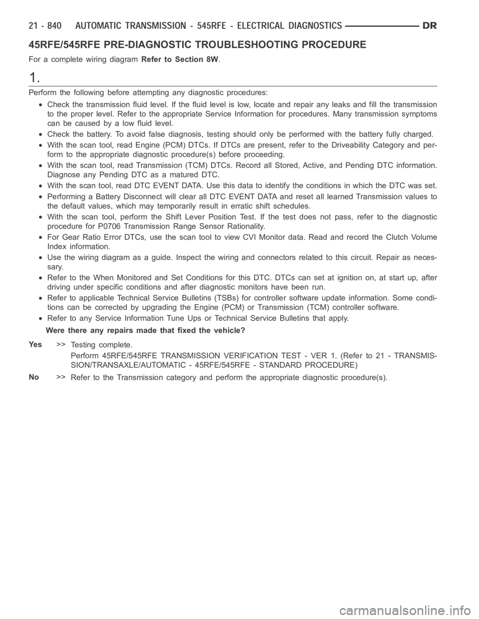
45RFE/545RFE PRE-DIAGNOSTIC TROUBLESHOOTING PROCEDURE
For a complete wiring diagramRefer to Section 8W.
1.
Perform the following before attempting any diagnostic procedures:
Check the transmission fluid level. Ifthe fluid level is low, locate and repair any leaks and fill the transmission
to the proper level. Refer to the appropriate Service Information for procedures. Many transmission symptoms
can be caused by a low fluid level.
Check the battery. To avoid false diagnosis, testing should only be performed with the battery fully charged.
With the scan tool, read Engine (PCM) DTCs. If DTCs are present, refer to theDriveability Category and per-
form to the appropriate diagnostic procedure(s) before proceeding.
With the scan tool, read Transmission (TCM) DTCs. Record all Stored, Active, and Pending DTC information.
Diagnose any Pending DTC as a matured DTC.
With the scan tool, read DTC EVENT DATA.Use this data to identify the conditions in which the DTC was set.
Performing a Battery Disconnect will clear all DTC EVENT DATA and reset alllearned Transmission values to
the default values, which may temporarily result in erratic shift schedules.
With the scan tool, perform the Shift Lever Position Test. If the test does not pass, refer to the diagnostic
procedure for P0706 Transmission Range Sensor Rationality.
For Gear Ratio Error DTCs, use the scan tool to view CVI Monitor data. Read and record the Clutch Volume
Index information.
Use the wiring diagram as a guide. Inspect the wiring and connectors related to this circuit. Repair as neces-
sary.
Refer to the When Monitored and Set Conditions for this DTC. DTCs can set at ignition on, at start up, after
driving under specific conditions and after diagnostic monitors have beenrun.
Refer to applicable Technical Service Bulletins (TSBs) for controller software update information. Some condi-
tions can be corrected by upgrading the Engine (PCM) or Transmission (TCM)controller software.
Refer to any Service Information Tune Ups or Technical Service Bulletins that apply.
Were there any repairs made that fixed the vehicle?
Ye s>>
Testing complete.
Perform 45RFE/545RFE TRANSMISSION VERIFICATION TEST - VER 1. (Refer to 21- TRANSMIS-
SION/TRANSAXLE/AUTOMATIC - 45RFE/545RFE - STANDARD PROCEDURE)
No>>
Refer to the Transmission category and perform the appropriate diagnostic procedure(s).