Page 3321 of 5267

P1736-GEAR RATIO ERROR IN 2ND PRIME
For a complete wiring diagramRefer to Section 8W.
When Monitored:
Continuously with the ignition on, engine running, with the transmissionin gear.
Set Condition:
If the ratio of the Input RPM to the Output RPM does not match the current gearratio. This DTC can take up
to five minutes of problem identification before illuminating the MIL
Possible Causes
RELATED DTC’S PRESENT
INPUT SPEED SENSOR OR WIRING
LOW FLUID LEVEL
CRACKED OR MIS-INSTALLED PRIMARY OIL FILTER OR SEAL
WORN SOLENOID SWITCH VALVE OR PLUGS
STUCK OR STICKING MAIN REGULATOR VALVE
BURNED UD OR 4C CLUTCH
CUT 4C OR UD PISTON SEAL
BROKEN 4C PISTON CASTING
BROKEN OR MISSING 4C BLEED ORIFICE
BROKEN OR MISSING UD BLEED ORIFICE
CUT 4C OR UD ACCUMULATOR PISTON SEAL
CRACKED 4C OR UD ACCUMULATOR PISTON
EXTRA CHECK BALL IN PASSAGE DOWNSTREAM OF #7 CHECK BALL POCKET
TRANSMISSION SOLENOID/TRS ASSEMBLY
BROKEN WELD - REACTION CARRIER TO REVERSE SUN GEAR
MISSING TEETH ON INPUT CLUTCH HUB TONE WHEEL
Always perform the 45RFE/545RFE Pre-Diagnostic Troubleshooting Procedure before proceeding. (Refer to
21 - TRANSMISSION/TRANSAXLE/AUTOMATIC - 45RFE/545RFE - STANDARD PROCEDURE)
Theory of Operation
The transmission system uses two speed sensors, one to measure input RPM and one to measure output RPM.
These inputs are essential for proper transmission operation. Therefore, the integrity of this data is verified through
the following checks:
1) When in gear, if the gear ratio does not compare to a known gear ratio, the corresponding in-gear trouble code
is set (DTCs P0731-36).
2) An excessive change in input or output speeds indicating signal intermittent which may result in the DTCs P0715
and/or P0720 to set.
3) If the common speed sensor ground circuit is lost, both sensor inputs will read the signal from the input speed
sensor at idle in neutral. Since the input speed sensor reads 60 teeth from the input clutch hub and the output
speed sensor reads 30 teeth from the park gear, the result is an apparent speed ratio of 1:2 and may cause the
DTC P1794 to set when at a stop.
Page 3326 of 5267
P1775-SOLENOID SWITCH VALVE LATCHED IN TCC POSITION
For a complete wiring diagramRefer to Section 8W.
Page 3330 of 5267
P1776-SOLENOID SWITCH VALVE LATCHED IN LR POSITION
For a complete wiring diagramRefer to Section 8W.
Page 3334 of 5267

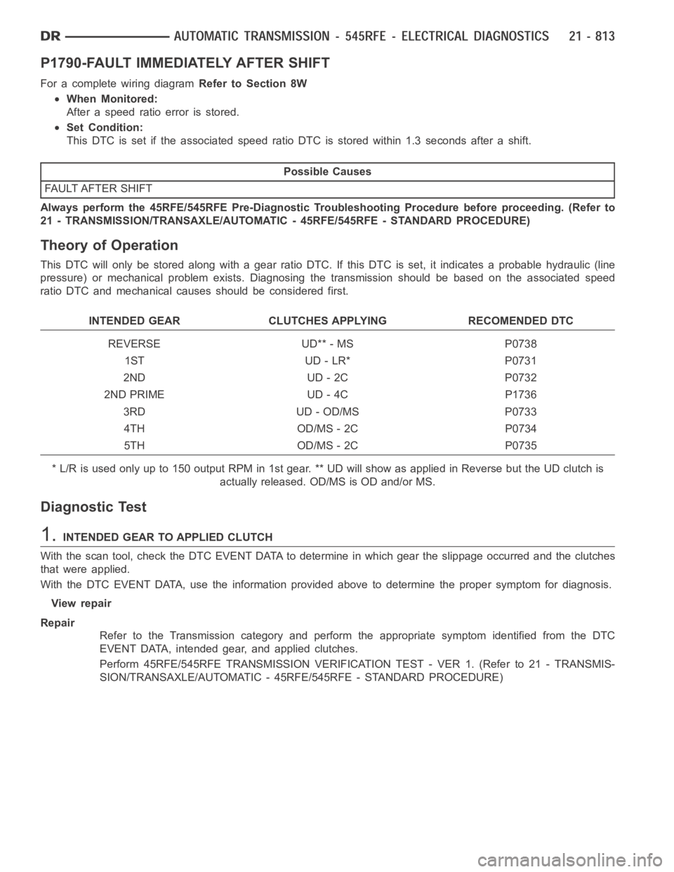
P1790-FAULT IMMEDIATELY AFTER SHIFT
For a complete wiring diagramRefer to Section 8W
When Monitored:
After a speed ratio error is stored.
Set Condition:
This DTC is set if the associated speed ratio DTC is stored within 1.3 seconds after a shift.
Possible Causes
FAULT AFTER SHIFT
Always perform the 45RFE/545RFE Pre-Diagnostic Troubleshooting Procedure before proceeding. (Refer to
21 - TRANSMISSION/TRANSAXLE/AUTOMATIC - 45RFE/545RFE - STANDARD PROCEDURE)
Theory of Operation
This DTC will only be stored along with a gear ratio DTC. If this DTC is set, itindicates a probable hydraulic (line
pressure) or mechanical problem exists. Diagnosing the transmission should be based on the associated speed
ratio DTC and mechanical causes should be considered first.
INTENDED GEAR CLUTCHES APPLYING RECOMENDED DTC
REVERSE UD** - MS P0738
1ST UD - LR* P0731
2ND UD - 2C P0732
2ND PRIME UD - 4C P1736
3RD UD - OD/MS P0733
4TH OD/MS - 2C P0734
5TH OD/MS - 2C P0735
* L/R is used only up to 150 output RPM in 1st gear. ** UD will show as applied inReversebuttheUDclutchis
actually released. OD/MS is OD and/or MS.
Diagnostic Test
1.INTENDED GEAR TO APPLIED CLUTCH
With the scan tool, check the DTC EVENT DATA to determine in which gear the slippage occurred and the clutches
that were applied.
WiththeDTCEVENTDATA,usetheinformationprovidedabovetodeterminethe proper symptom for diagnosis.
View repair
Repair
Refer to the Transmission category and perform the appropriate symptom identified from the DTC
EVENT DATA, intended gear, and applied clutches.
Perform 45RFE/545RFE TRANSMISSION VERIFICATION TEST - VER 1. (Refer to 21- TRANSMIS-
SION/TRANSAXLE/AUTOMATIC - 45RFE/545RFE - STANDARD PROCEDURE)
Page 3335 of 5267
P1794-SPEED SENSOR GROUND ERROR
For a complete wiring diagramRefer to Section 8W
Page 3339 of 5267

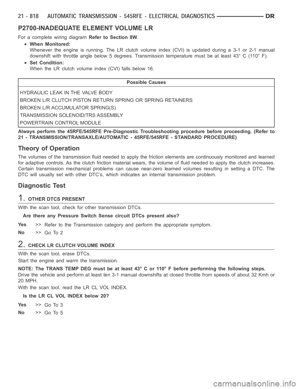
P2700-INADEQUATE ELEMENT VOLUME LR
For a complete wiring diagramRefer to Section 8W.
When Monitored:
Whenever the engine is running. The LR clutch volume index (CVI) is updatedduring a 3-1 or 2-1 manual
downshift with throttle angle below 5 degrees. Transmission temperaturemust be at least 43° C (110° F).
Set Condition:
When the LR clutch volume index (CVI) falls below 16.
Possible Causes
HYDRAULIC LEAK IN THE VALVE BODY
BROKEN L/R CLUTCH PISTON RETURN SPRING OR SPRING RETAINERS
BROKEN L/R ACCUMULATOR SPRING(S)
TRANSMISSION SOLENOID/TRS ASSEMBLY
POWERTRAIN CONTROL MODULE
Always perform the 45RFE/545RFE Pre-Diagnostic Troubleshooting procedure before proceeding. (Refer to
21 - TRANSMISSION/TRANSAXLE/AUTOMATIC - 45RFE/545RFE - STANDARD PROCEDURE)
Theory of Operation
The volumes of the transmission fluid needed to apply the friction elements are continuously monitored and learned
for adaptive controls. As the clutch friction material wears, the volume of fluid needed to apply the clutch increases.
Certain transmission mechanical problems can cause near-zero learned volumes resulting in setting a DTC. The
DTC will usually set with other DTC’s, which indicates an internal transmission problem.
Diagnostic Test
1.OTHER DTCS PRESENT
With the scan tool, check for other transmission DTCs.
Are there any Pressure Switch Sense circuit DTCs present also?
Ye s>>
Refer to the Transmission category and perform the appropriate symptom.
No>>
Go To 2
2.CHECKLRCLUTCHVOLUMEINDEX
With the scan tool, erase DTCs.
Start the engine and warm the transmission.
NOTE: The TRANS TEMP DEG must be at least 43° C or 110° F before performing thefollowing steps.
Drive the vehicle and perform at least ten 3-1 manual downshifts at closed throttle from speeds of about 32 Kmh or
20 MPH.
With the scan tool, read the LR CL VOL INDEX.
Is the LR CL VOL INDEX below 20?
Ye s>>
Go To 3
No>>
Go To 5
Page 3341 of 5267

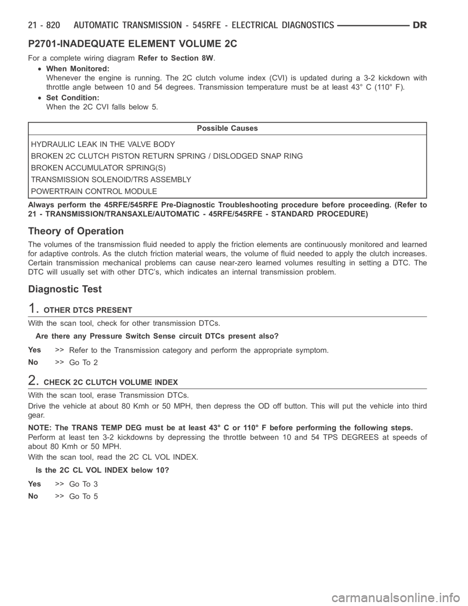
P2701-INADEQUATE ELEMENT VOLUME 2C
For a complete wiring diagramRefer to Section 8W.
When Monitored:
Whenever the engine is running. The 2C clutch volume index (CVI) is updatedduring a 3-2 kickdown with
throttle angle between 10 and 54 degrees. Transmission temperature must be at least 43° C (110° F).
Set Condition:
When the 2C CVI falls below 5.
Possible Causes
HYDRAULIC LEAK IN THE VALVE BODY
BROKEN 2C CLUTCH PISTON RETURN SPRING / DISLODGED SNAP RING
BROKEN ACCUMULATOR SPRING(S)
TRANSMISSION SOLENOID/TRS ASSEMBLY
POWERTRAIN CONTROL MODULE
Always perform the 45RFE/545RFE Pre-Diagnostic Troubleshooting procedure before proceeding. (Refer to
21 - TRANSMISSION/TRANSAXLE/AUTOMATIC - 45RFE/545RFE - STANDARD PROCEDURE)
Theory of Operation
The volumes of the transmission fluid needed to apply the friction elements are continuously monitored and learned
for adaptive controls. As the clutch friction material wears, the volume of fluid needed to apply the clutch increases.
Certain transmission mechanical problems can cause near-zero learned volumes resulting in setting a DTC. The
DTC will usually set with other DTC’s, which indicates an internal transmission problem.
Diagnostic Test
1.OTHER DTCS PRESENT
With the scan tool, check for other transmission DTCs.
Are there any Pressure Switch Sense circuit DTCs present also?
Ye s>>
Refer to the Transmission category and perform the appropriate symptom.
No>>
Go To 2
2.CHECK2CCLUTCHVOLUMEINDEX
With the scan tool, erase Transmission DTCs.
Drive the vehicle at about 80 Kmh or 50 MPH, then depress the OD off button. This will put the vehicle into third
gear.
NOTE: The TRANS TEMP DEG must be at least 43° C or 110° F before performing thefollowing steps.
Perform at least ten 3-2 kickdowns by depressing the throttle between 10 and 54 TPS DEGREES at speeds of
about 80 Kmh or 50 MPH.
With the scan tool, read the 2C CL VOL INDEX.
Is the 2C CL VOL INDEX below 10?
Ye s>>
Go To 3
No>>
Go To 5
Page 3343 of 5267

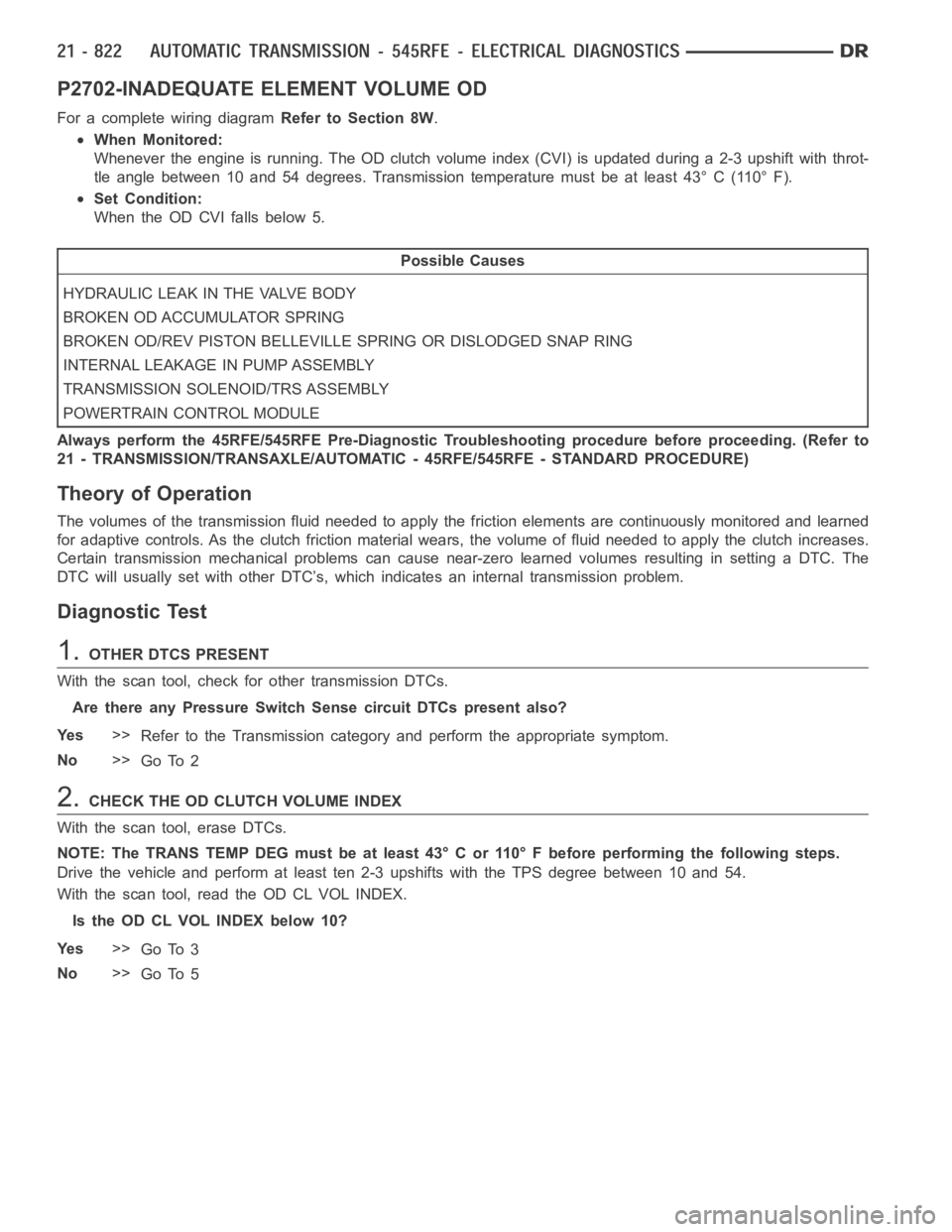
P2702-INADEQUATE ELEMENT VOLUME OD
For a complete wiring diagramRefer to Section 8W.
When Monitored:
Whenever the engine is running. The OD clutch volume index (CVI) is updatedduring a 2-3 upshift with throt-
tle angle between 10 and 54 degrees. Transmission temperature must be at least 43° C (110° F).
Set Condition:
When the OD CVI falls below 5.
Possible Causes
HYDRAULIC LEAK IN THE VALVE BODY
BROKEN OD ACCUMULATOR SPRING
BROKEN OD/REV PISTON BELLEVILLE SPRING OR DISLODGED SNAP RING
INTERNAL LEAKAGE IN PUMP ASSEMBLY
TRANSMISSION SOLENOID/TRS ASSEMBLY
POWERTRAIN CONTROL MODULE
Always perform the 45RFE/545RFE Pre-Diagnostic Troubleshooting procedure before proceeding. (Refer to
21 - TRANSMISSION/TRANSAXLE/AUTOMATIC - 45RFE/545RFE - STANDARD PROCEDURE)
Theory of Operation
The volumes of the transmission fluid needed to apply the friction elements are continuously monitored and learned
for adaptive controls. As the clutch friction material wears, the volume of fluid needed to apply the clutch increases.
Certain transmission mechanical problems can cause near-zero learned volumes resulting in setting a DTC. The
DTC will usually set with other DTC’s, which indicates an internal transmission problem.
Diagnostic Test
1.OTHER DTCS PRESENT
With the scan tool, check for other transmission DTCs.
Are there any Pressure Switch Sense circuit DTCs present also?
Ye s>>
Refer to the Transmission category and perform the appropriate symptom.
No>>
Go To 2
2.CHECK THE OD CLUTCH VOLUME INDEX
With the scan tool, erase DTCs.
NOTE: The TRANS TEMP DEG must be at least 43° C or 110° F before performing thefollowing steps.
Drive the vehicle and perform at least ten 2-3 upshifts with the TPS degree between 10 and 54.
With the scan tool, read the OD CL VOL INDEX.
Is the OD CL VOL INDEX below 10?
Ye s>>
Go To 3
No>>
Go To 5