2006 DODGE RAM SRT-10 automatic transmission
[x] Cancel search: automatic transmissionPage 3693 of 5267
Theory of Operation
The 3-4 Solenoid is used the engage the gear change from 3rd gear to 4th gear.
The solenoids used in transmission applications are attached to valves which can be classified as normally open or
normally closed. The normally open solenoid valve is defined as a valve which allows hydraulic flow when no cur-
rent or voltage is applied to the solenoid. The normally closed solenoid valve is defined as a valve which does not
allow hydraulic flow when no current or voltage is applied to the solenoid.These valves perform hydraulic control
functions for the transmission and must therefore be durable and tolerantof dirt particles. For these reasons, the
valves have hardened steel poppets and ball valves. The solenoids operatethe valves directly, which means that
the solenoids must have very high outputs to close the valves against the sizable flow areas and line pressures
found in current transmissions. Fastresponse time is also necessary to ensure accurate control.
When Monitored:
Continuously with ignition on.
Set Condition:
This code will set if the voltage detected on the 3-4 Shift Solenoid Controlcircuit at the ECM is different then
the expected voltage. Note: To clear this DTC it is necessary to drive the vehicle at a sustained speed which
would allow the TCC and/or Overdrive Clutch to operate
Possible Causes
TRANSMISSION CONTROL DTC PRESENT
(T9) 3-4 SOLENOID CONTROL CIRCUIT SHORT TO VOLTAGE
(T9) 3-4 SOLENOID CONTROL CIRCUIT SHORT TO ANOTHER CIRCUIT
3-4 SOLENOID
ENGINE CONTROL MODULE
Always perform the Pre-Diagnostic Troubleshooting procedure before proceeding. (Refer to 21 - TRANSMIS-
SION/TRANSAXLE/AUTOMATIC - 48RE - STANDARD PROCEDURE)
Diagnostic Test
1.CHECK IF ANY TRANSMISSION CONTROL DTCS ARE PRESENT
Ignition on, engine not running.
With the scan tool, read Engine DTCs.
Are there any Transmission Control DTC’s present?
Ye s>>
Refer to the Transmission category, (Refer to 21 - TRANSMISSION/TRANSAXLE/AUTOMATIC - 48RE
- DIAGNOSIS AND TESTING) and perform the appropriate symptom(s).
No>>
Go To 2
2.CHECK IF THE DTC IS CURRENT
Ignition on, engine not running.
With the scan tool, read Engine DTCs.
Record the Freeze Frame data for the reported DTC.
With the scan tool, erase DTCs.
Turn the ignition off to the lock position.
Using the Freeze Frame data recorded earlier, try to duplicate the conditions in which the DTC originally set.
NOTE: It may be necessary to road test the vehicle to duplicate the originalset conditions.
With the scan tool, read Engine DTCs.
Did the DTC reset?
Ye s>>
Go To 3
No>>
Go To 7
Page 3694 of 5267
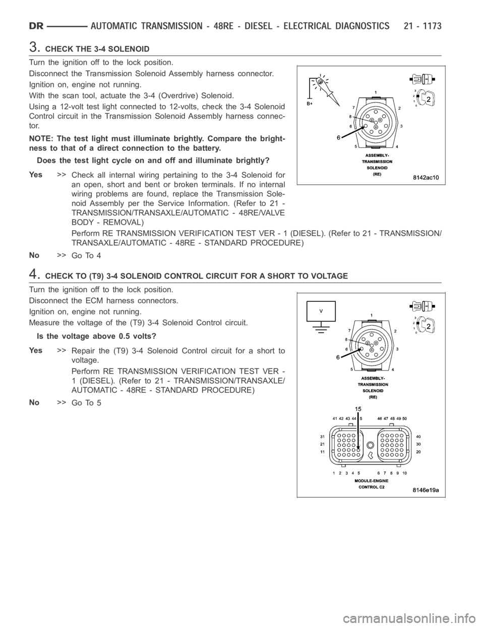
3.CHECK THE 3-4 SOLENOID
Turn the ignition off to the lock position.
Disconnect the Transmission Solenoid Assembly harness connector.
Ignition on, engine not running.
With the scan tool, actuate the 3-4 (Overdrive) Solenoid.
Using a 12-volt test light connected to 12-volts, check the 3-4 Solenoid
Control circuit in the TransmissionSolenoid Assembly harness connec-
tor.
NOTE: The test light must illuminate brightly. Compare the bright-
ness to that of a direct connection to the battery.
Does the test light cycle on and off and illuminate brightly?
Ye s>>
Check all internal wiring pertaining to the 3-4 Solenoid for
an open, short and bent or broken terminals. If no internal
wiring problems are found, replace the Transmission Sole-
noid Assembly per the Service Information. (Refer to 21 -
TRANSMISSION/TRANSAXLE/AUTOMATIC - 48RE/VALVE
BODY - REMOVAL)
Perform RE TRANSMISSION VERIFICATION TEST VER - 1 (DIESEL). (Refer to 21 - TRANSMISSION/
TRANSAXLE/AUTOMATIC - 48RE - STANDARD PROCEDURE)
No>>
Go To 4
4.CHECK TO (T9) 3-4 SOLENOID CONTROL CIRCUIT FOR A SHORT TO VOLTAGE
Turn the ignition off to the lock position.
Disconnect the ECM harness connectors.
Ignition on, engine not running.
Measure the voltage of the (T9) 3-4 Solenoid Control circuit.
Is the voltage above 0.5 volts?
Ye s>>
Repair the (T9) 3-4 Solenoid Control circuit for a short to
voltage.
Perform RE TRANSMISSION VERIFICATION TEST VER -
1 (DIESEL). (Refer to 21 - TRANSMISSION/TRANSAXLE/
AUTOMATIC - 48RE - STANDARD PROCEDURE)
No>>
Go To 5
Page 3695 of 5267
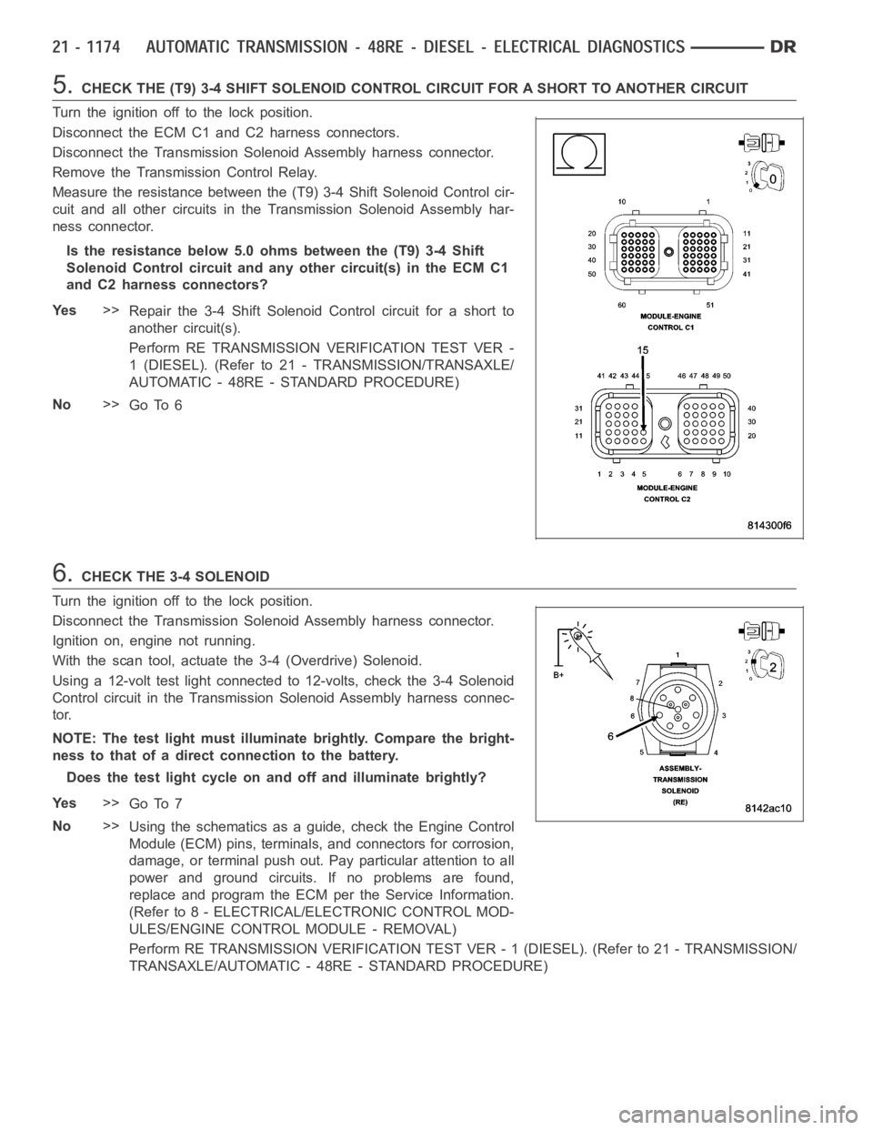
5.CHECK THE (T9) 3-4 SHIFT SOLENOID CONTROL CIRCUIT FOR A SHORT TO ANOTHER CIRCUIT
Turn the ignition off to the lock position.
Disconnect the ECM C1 and C2 harness connectors.
Disconnect the Transmission Solenoid Assembly harness connector.
Remove the Transmission Control Relay.
Measure the resistance between the (T9) 3-4 Shift Solenoid Control cir-
cuit and all other circuits in the Transmission Solenoid Assembly har-
ness connector.
Is the resistance below 5.0 ohms between the (T9) 3-4 Shift
Solenoid Control circuit and anyother circuit(s) in the ECM C1
and C2 harness connectors?
Ye s>>
Repair the 3-4 Shift Solenoid Control circuit for a short to
another circuit(s).
Perform RE TRANSMISSION VERIFICATION TEST VER -
1 (DIESEL). (Refer to 21 - TRANSMISSION/TRANSAXLE/
AUTOMATIC - 48RE - STANDARD PROCEDURE)
No>>
Go To 6
6.CHECK THE 3-4 SOLENOID
Turn the ignition off to the lock position.
Disconnect the Transmission Solenoid Assembly harness connector.
Ignition on, engine not running.
With the scan tool, actuate the 3-4 (Overdrive) Solenoid.
Using a 12-volt test light connected to 12-volts, check the 3-4 Solenoid
Control circuit in the TransmissionSolenoid Assembly harness connec-
tor.
NOTE: The test light must illuminate brightly. Compare the bright-
ness to that of a direct connection to the battery.
Does the test light cycle on and off and illuminate brightly?
Ye s>>
Go To 7
No>>
Using the schematics as a guide, check the Engine Control
Module (ECM) pins, terminals, and connectors for corrosion,
damage, or terminal push out. Pay particular attention to all
power and ground circuits. If no problems are found,
replace and program the ECM per the Service Information.
(Refer to 8 - ELECTRICAL/ELECTRONIC CONTROL MOD-
ULES/ENGINE CONTROL MODULE - REMOVAL)
Perform RE TRANSMISSION VERIFICATION TEST VER - 1 (DIESEL). (Refer to 21 - TRANSMISSION/
TRANSAXLE/AUTOMATIC - 48RE - STANDARD PROCEDURE)
Page 3696 of 5267
7.INTERMITTENT WIRING AND CONNECTORS
The conditions necessary set this DTC are not present at this time.
Use the Freeze Frame Data to help duplicate the conditions that set the DTC.Pay particular attention to the DTC
set conditions, such as, VSS, MAP, ECT, and Load.
Visually inspect the related wiring harness. Look for any chafed, pierced, pinched, or partially broken wires.
Visually inspect the related wiring harness connectors. Look for broken,bent, pushed out, or corroded terminals.
Refer to any technical service bulletins that may apply.
Were there any problems found?
Ye s>>
Repair as necessary.
Perform RE TRANSMISSION VERIFICATION TEST VER - 1 (DIESEL). (Refer to 21 - TRANSMISSION/
TRANSAXLE/AUTOMATIC - 48RE - STANDARD PROCEDURE)
No>>
Te s t C o m p l e t e .
Page 3698 of 5267
When Monitored:
With the ignition on. Battery voltage greater than 10 volts.
Set Condition:
A shorted condition is detected in the TIPM Transmission Control Output circuit.
Possible Causes
(T16) TRANSMISSION CONTROL OUTPUT CIRCUIT SHORTED TO GROUND
TOTALLY INTEGRATED POWER MODULE (TIPM)
Diagnostic Test
1.CHECK IF THE DTC IS ACTIVE
Ignition on, engine not running.
With the scan tool, select View DTCs.
Is the status Active for this DTC?
Ye s>>
Go to 2
No>>
Go to 5
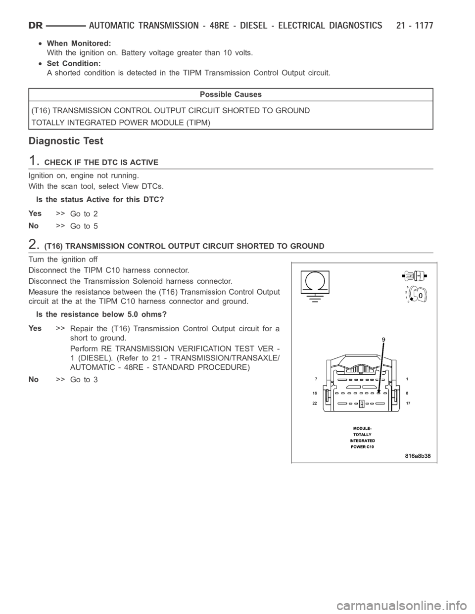
2.(T16) TRANSMISSION CONTROL OUTPUT CIRCUIT SHORTED TO GROUND
Turn the ignition off
Disconnect the TIPM C10 harness connector.
Disconnect the Transmission Solenoid harness connector.
Measure the resistance between the (T16) Transmission Control Output
circuit at the at the TIPM C10 harness connector and ground.
Is the resistance below 5.0 ohms?
Ye s>>
Repair the (T16) Transmission Control Output circuit for a
short to ground.
Perform RE TRANSMISSION VERIFICATION TEST VER -
1 (DIESEL). (Refer to 21 - TRANSMISSION/TRANSAXLE/
AUTOMATIC - 48RE - STANDARD PROCEDURE)
No>>
Go to 3
Page 3699 of 5267
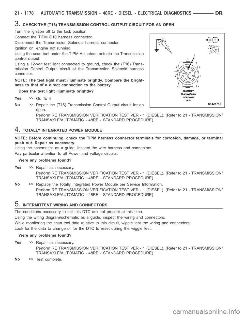
3.CHECK THE (T16) TRANSMISSION CONTROL OUTPUT CIRCUIT FOR AN OPEN
Turn the ignition off to the lock position.
Connect the TIPM C10 harness connector.
Disconnect the Transmission Solenoid harness connector.
Ignition on, engine not running.
Using the scan tool under the TIPM Actuators, actuate the Transmission
control output.
Using a 12-volt test light connected to ground, check the (T16) Trans-
mission Control Output circuit at the Transmission Solenoid harness
connector.
NOTE: The test light must illuminate brightly. Compare the bright-
ness to that of a direct connection to the battery.
Does the test light illuminate brightly?
Ye s>>
Go To 4
No>>
Repair the (T16) Transmission Control Output circuit for an
open.
Perform RE TRANSMISSION VERIFICATION TEST VER - 1 (DIESEL). (Refer to 21 - TRANSMISSION/
TRANSAXLE/AUTOMATIC - 48RE - STANDARD PROCEDURE)
4.TOTALLY INTEGRATED POWER MODULE
NOTE: Before continuing, check the TIPM harness connector terminals for corrosion, damage, or terminal
push out. Repair as necessary.
Using the schematics as a guide, inspect the wire harness and connectors.
Pay particular attention to allPower and voltage circuits.
Were any problems found?
Ye s>>
Repair as necessary.
Perform RE TRANSMISSION VERIFICATION TEST VER - 1 (DIESEL). (Refer to 21 - TRANSMISSION/
TRANSAXLE/AUTOMATIC - 48RE - STANDARD PROCEDURE)
No>>
Replace the Totally Integrated Power Module per Service Information.
Perform RE TRANSMISSION VERIFICATION TEST VER - 1 (DIESEL). (Refer to 21 - TRANSMISSION/
TRANSAXLE/AUTOMATIC - 48RE - STANDARD PROCEDURE)
5.INTERMITTENT WIRING AND CONNECTORS
The conditions necessary to set this DTC are not present at this time.
Using the wiring diagram/schematic as a guide, inspect the wiring and connectors.
While monitoring the scan tool data relative to this circuit, wiggle test the wiring and connectors.
Look for the data to change or for the DTC to reset during the wiggle test.
Were any problems found?
Ye s>>
Repair as necessary.
Perform RE TRANSMISSION VERIFICATION TEST VER - 1 (DIESEL). (Refer to 21 - TRANSMISSION/
TRANSAXLE/AUTOMATIC - 48RE - STANDARD PROCEDURE)
No>>
Te s t c o m p l e t e .
Page 3701 of 5267
When Monitored:
With the ignition on. Battery voltage greater than 10 volts.
Set Condition:
A shorted condition is detected in the TIPM Transmission Control Output circuit.
Possible Causes
(T16) TRANSMISSION CONTROL OUTPUT CIRCUIT SHORTED TO POWER
TOTALLY INTEGRATED POWER MODULE (TIPM)
Diagnostic Test
1.CHECK IF THE DTC IS ACTIVE
Ignition on, engine not running.
With the scan tool, select View DTCs.
Is the status Active for this DTC?
Ye s>>
Go to 2
No>>
Go to 4
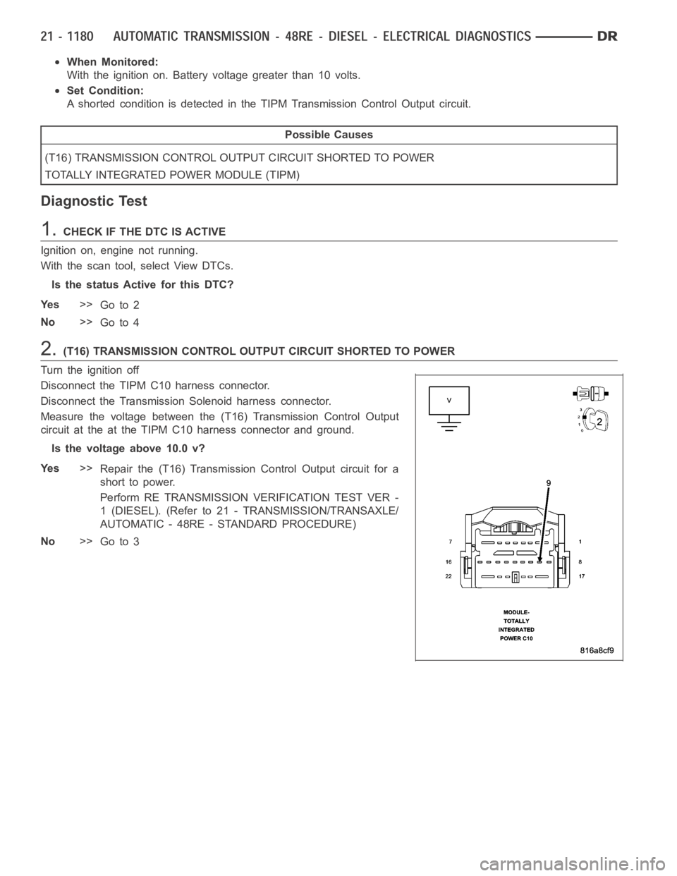
2.(T16) TRANSMISSION CONTROL OUTPUT CIRCUIT SHORTED TO POWER
Turn the ignition off
Disconnect the TIPM C10 harness connector.
Disconnect the Transmission Solenoid harness connector.
Measure the voltage between the (T16) Transmission Control Output
circuit at the at the TIPM C10 harness connector and ground.
Is the voltage above 10.0 v?
Ye s>>
Repair the (T16) Transmission Control Output circuit for a
short to power.
Perform RE TRANSMISSION VERIFICATION TEST VER -
1 (DIESEL). (Refer to 21 - TRANSMISSION/TRANSAXLE/
AUTOMATIC - 48RE - STANDARD PROCEDURE)
No>>
Go to 3
Page 3702 of 5267
3.TOTALLY INTEGRATED POWER MODULE
NOTE: Before continuing, check the TIPM harness connector terminals for corrosion, damage, or terminal
push out. Repair as necessary.
Using the schematics as a guide, inspect the wire harness and connectors.
Pay particular attention to allPower and voltage circuits.
Were any problems found?
Ye s>>
Repair as necessary.
Perform RE TRANSMISSION VERIFICATION TEST VER - 1 (DIESEL). (Refer to 21 - TRANSMISSION/
TRANSAXLE/AUTOMATIC - 48RE - STANDARD PROCEDURE)
No>>
Replace the Totally Integrated Power Module per Service Information.
Perform RE TRANSMISSION VERIFICATION TEST VER - 1 (DIESEL). (Refer to 21 - TRANSMISSION/
TRANSAXLE/AUTOMATIC - 48RE - STANDARD PROCEDURE)
4.INTERMITTENT WIRING AND CONNECTORS
The conditions necessary to set this DTC are not present at this time.
Using the wiring diagram/schematic as a guide, inspect the wiring and connectors.
While monitoring the scan tool data relative to this circuit, wiggle test the wiring and connectors.
Look for the data to change or for the DTC to reset during the wiggle test.
Were any problems found?
Ye s>>
Repair as necessary.
Perform RE TRANSMISSION VERIFICATION TEST VER - 1 (DIESEL). (Refer to 21 - TRANSMISSION/
TRANSAXLE/AUTOMATIC - 48RE - STANDARD PROCEDURE)
No>>
Te s t c o m p l e t e .