2006 DODGE RAM SRT-10 automatic transmission
[x] Cancel search: automatic transmissionPage 28 of 5267

Theory of Operation
The Park Neutral switch rationality test is enabled only for vehicles equipped with a 4/5 speed automatic transmis-
sion. This diagnostic checks if the park/neutral switch is incorrectly stuck in the neutral position during driving con-
ditions by comparing Vehicle Speed, Engine Speed, Throttle Position, andPressure Ratio to the fail thresholds and
by looking at the state of the Park/Neutral Switch. The stuck in drive condition is not explicitly checked as the starter
relay does not energize and therefore render the vehicle inoperable.
When Monitored:
Continuously with the transmission in Park, Neutral, or Drive and NOT in Limp-in mode.
Set Condition:
This code will set if the PCM detects an incorrect Park/Neutral switch state for a given mode of vehicle oper-
ation. One trip fault. Three good trips to turn off the MIL.
Possible Causes
TRS (T41) SENSE (P/N SENSE) CIRCUIT OPEN
TRS (T41) SENSE (P/N SENSE) CIRCUIT SHORTED TO GROUND
TRANSMISSION RANGE SENSOR
PCM
Always perform the Pre-Diagnostic Troubleshooting procedure before proceeding. (Refer to 9 - ENGINE -
DIAGNOSIS AND TESTING).
Diagnostic Test
1.P/N AND D/R NOT IN CORRECT POSITION
NOTE: Check the TCM for DTCs, if P0706 is set in the TCM diagnose the TCM code before continuing.
Ignition on, engine not running.
With the scan tool, read the Park/Neutral Position Switch input state.
While moving the gear selector through all gear positions (Park to 1 and back to Park), monitor the scan tool dis-
play.
Did the scan tool display show P/N and D/R in the correct gear positions?
Ye s>>
Refer to the INTERMITTENT CONDITION Diagnostic Procedure.
Perform the POWERTRAIN VERIFICATION TEST. (Refer to 9 - ENGINE - STANDARD PROCEDURE)
No>>
Go To 2
Page 439 of 5267

3.EXCESSIVE RESISTANCE IN THE BATTERY CIRCUIT
Turn the ignition off.
Check the Battery Cables for excessive resistance using the service information procedure.
Did either Battery Cable have a voltage drop greater than 0.2 of a volt?
Ye s>>
Repair the excessive resistance in the Battery circuit.
Perform the POWERTRAIN VERIFICATION TEST. (Refer to 9 - ENGINE - STANDARD PROCEDURE)
No>>
Go To 4
4.STARTER RELAY
Turn ignition off.
Remove the Starter Relay from IPM.
CAUTION: The Parking Brake must be on and the Transmission must be in park for a vehicle equipped with
an automatic transmission.
WARNING: When the engine is operating, do not stand in direct line with the fan. Do not put your hands
near the pulleys, belts, or fan. Do notwear loose clothing. Failure to follow these instructions can result in
personal injury or death.
Briefly connect a jumper wire from the Internal Fused B+ circuit to the (T750) Starter Relay Output circuit.
Did the Starter Motor crank the engine?
Ye s>>
Go To 5
No>>
Go To 7
5.(T751) FUSED IGNITION SWITCH OUTPUT CIRCUIT
Ignition on, engine not running.
Using a 12-volt test light, probe the (T751) Fused Ignition Switch Output circuit in the Starter Relay connector.
While observing 12-volt test light, hold ignition key in the start position.
Does the test light illuminate brightly?
Ye s>>
Go To 6
No>>
Repair the excessive resistance in the(T751)FusedIgnitionSwitchOutput circuit. Inspect related fuses
and repair as necessary.
Perform the POWERTRAIN VERIFICATION TEST. (Refer to 9 - ENGINE - STANDARD PROCEDURE)
Page 1495 of 5267
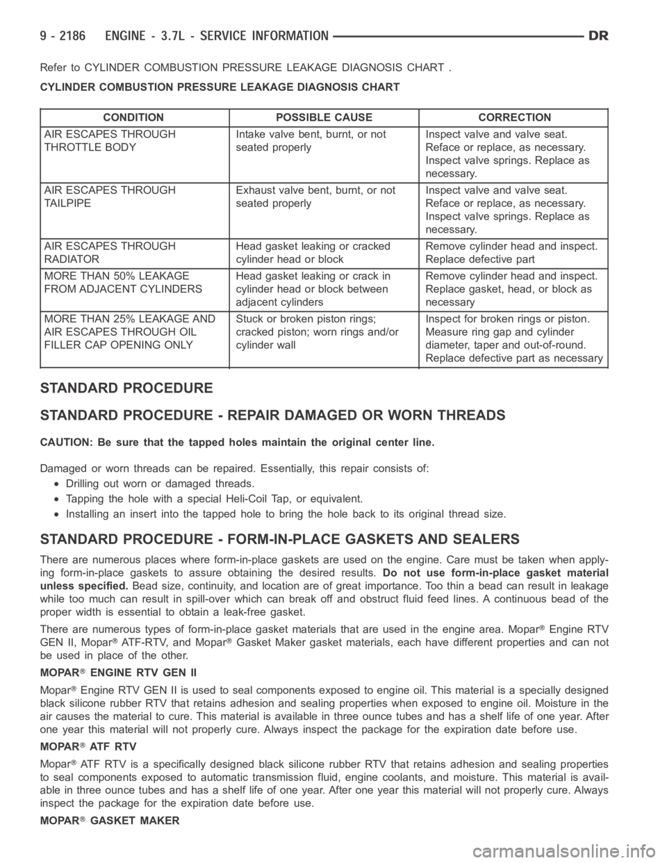
Refer to CYLINDER COMBUSTION PRESSURE LEAKAGE DIAGNOSIS CHART .
CYLINDER COMBUSTION PRESSURE LEAKAGE DIAGNOSIS CHART
CONDITION POSSIBLE CAUSE CORRECTION
AIR ESCAPES THROUGH
THROTTLE BODYIntake valve bent, burnt, or not
seated properlyInspect valve and valve seat.
Reface or replace, as necessary.
Inspect valve springs. Replace as
necessary.
AIR ESCAPES THROUGH
TAILPIPEExhaust valve bent, burnt, or not
seated properlyInspect valve and valve seat.
Reface or replace, as necessary.
Inspect valve springs. Replace as
necessary.
AIR ESCAPES THROUGH
RADIATORHead gasket leaking or cracked
cylinder head or blockRemove cylinder head and inspect.
Replace defective part
MORE THAN 50% LEAKAGE
FROM ADJACENT CYLINDERSHead gasket leaking or crack in
cylinder head or block between
adjacent cylindersRemove cylinder head and inspect.
Replace gasket, head, or block as
necessary
MORE THAN 25% LEAKAGE AND
AIR ESCAPES THROUGH OIL
FILLER CAP OPENING ONLYStuckorbrokenpistonrings;
cracked piston; worn rings and/or
cylinder wallInspect for broken rings or piston.
Measure ring gap and cylinder
diameter, taper and out-of-round.
Replace defective part as necessary
STANDARD PROCEDURE
STANDARD PROCEDURE - REPAIR DAMAGED OR WORN THREADS
CAUTION: Be sure that the tapped holes maintain the original center line.
Damaged or worn threads can be repaired. Essentially, this repair consistsof:
Drilling out worn or damaged threads.
Tapping the hole with a special Heli-Coil Tap, or equivalent.
Installing an insert into the tapped hole to bring the hole back to its original thread size.
STANDARD PROCEDURE - FORM-IN-PLACE GASKETS AND SEALERS
There are numerous places where form-in-place gaskets are used on the engine. Care must be taken when apply-
ing form-in-place gaskets to assure obtaining the desired results.Do not use form-in-place gasket material
unless specified.Bead size, continuity, and location are of great importance. Too thin a bead can result in leakage
while too much can result in spill-overwhich can break off and obstruct fluid feed lines. A continuous bead of the
proper width is essential to obtain a leak-free gasket.
There are numerous types of form-in-place gasket materials that are used in the engine area. Mopar
Engine RTV
GEN II, Mopar
ATF-RTV, and MoparGasket Maker gasket materials, each have different properties and can not
be used in place of the other.
MOPAR
ENGINE RTV GEN II
Mopar
Engine RTV GEN II is used to seal components exposed to engine oil. This material is a specially designed
black silicone rubber RTV that retains adhesion and sealing properties when exposed to engine oil. Moisture in the
air causes the material to cure. This material is available in three ounce tubes and has a shelf life of one year. After
one year this material will not properly cure. Always inspect the package for the expiration date before use.
MOPAR
AT F R T V
Mopar
ATF RTV is a specifically designed black silicone rubber RTV that retains adhesion and sealing properties
to seal components exposed to automatic transmission fluid, engine coolants, and moisture. This material is avail-
able in three ounce tubes and has a shelf life of one year. After one year thismaterial will not properly cure. Always
inspect the package for the expiration date before use.
MOPAR
GASKET MAKER
Page 1566 of 5267
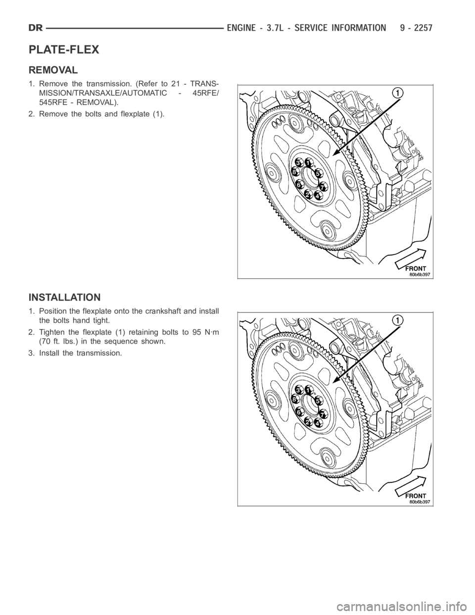
PLATE-FLEX
REMOVAL
1. Remove the transmission. (Refer to 21 - TRANS-
MISSION/TRANSAXLE/AUTOMATIC - 45RFE/
545RFE - REMOVAL).
2. Remove the bolts and flexplate (1).
INSTALLATION
1. Position the flexplate ontothe crankshaft and install
the bolts hand tight.
2. Tighten the flexplate (1) retaining bolts to 95 Nꞏm
(70 ft. lbs.) in the sequence shown.
3. Install the transmission.
Page 1629 of 5267
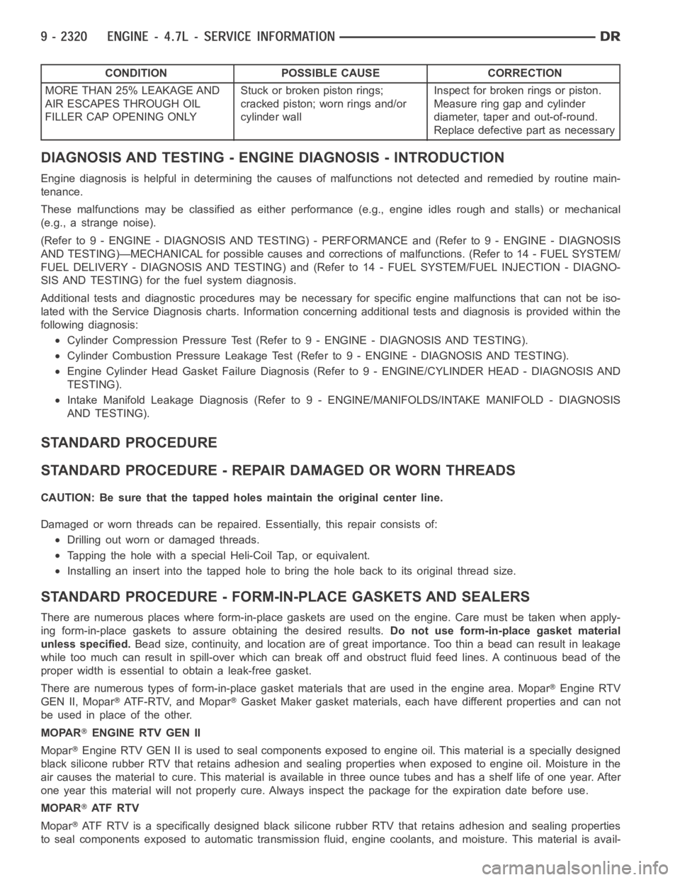
CONDITION POSSIBLE CAUSE CORRECTION
MORE THAN 25% LEAKAGE AND
AIR ESCAPES THROUGH OIL
FILLER CAP OPENING ONLYStuckorbrokenpistonrings;
cracked piston; worn rings and/or
cylinder wallInspect for broken rings or piston.
Measure ring gap and cylinder
diameter, taper and out-of-round.
Replace defective part as necessary
DIAGNOSIS AND TESTING - ENGINE DIAGNOSIS - INTRODUCTION
Engine diagnosis is helpful in determining the causes of malfunctions notdetected and remedied by routine main-
tenance.
These malfunctions may be classified as either performance (e.g., engineidles rough and stalls) or mechanical
(e.g., a strange noise).
(Refer to 9 - ENGINE - DIAGNOSIS AND TESTING) - PERFORMANCE and (Refer to 9 - ENGINE - DIAGNOSIS
AND TESTING)—MECHANICAL for possible causes and corrections of malfunctions. (Refer to 14 - FUEL SYSTEM/
FUEL DELIVERY - DIAGNOSIS AND TESTING) and (Refer to 14 - FUEL SYSTEM/FUEL INJECTION - DIAGNO-
SIS AND TESTING) for the fuel system diagnosis.
Additional tests and diagnostic procedures may be necessary for specificengine malfunctions that can not be iso-
lated with the Service Diagnosis charts. Information concerning additional tests and diagnosis is provided within the
following diagnosis:
Cylinder Compression Pressure Test (Refer to 9 - ENGINE - DIAGNOSIS AND TESTING).
Cylinder Combustion Pressure LeakageTest (Refer to 9 - ENGINE - DIAGNOSISAND TESTING).
Engine Cylinder Head Gasket Failure Diagnosis (Refer to 9 - ENGINE/CYLINDER HEAD - DIAGNOSIS AND
TESTING).
Intake Manifold Leakage Diagnosis (Refer to 9 - ENGINE/MANIFOLDS/INTAKEMANIFOLD - DIAGNOSIS
AND TESTING).
STANDARD PROCEDURE
STANDARD PROCEDURE - REPAIR DAMAGED OR WORN THREADS
CAUTION: Be sure that the tapped holes maintain the original center line.
Damaged or worn threads can be repaired. Essentially, this repair consistsof:
Drilling out worn or damaged threads.
Tapping the hole with a special Heli-Coil Tap, or equivalent.
Installing an insert into the tapped hole to bring the hole back to its original thread size.
STANDARD PROCEDURE - FORM-IN-PLACE GASKETS AND SEALERS
There are numerous places where form-in-place gaskets are used on the engine. Care must be taken when apply-
ing form-in-place gaskets to assure obtaining the desired results.Do not use form-in-place gasket material
unless specified.Bead size, continuity, and location are of great importance. Too thin a bead can result in leakage
while too much can result in spill-overwhich can break off and obstruct fluid feed lines. A continuous bead of the
proper width is essential to obtain a leak-free gasket.
There are numerous types of form-in-place gasket materials that are used in the engine area. Mopar
Engine RTV
GEN II, Mopar
ATF-RTV, and MoparGasket Maker gasket materials, each have different properties and can not
be used in place of the other.
MOPAR
ENGINE RTV GEN II
Mopar
Engine RTV GEN II is used to seal components exposed to engine oil. This material is a specially designed
black silicone rubber RTV that retains adhesion and sealing properties when exposed to engine oil. Moisture in the
air causes the material to cure. This material is available in three ounce tubes and has a shelf life of one year. After
one year this material will not properly cure. Always inspect the package for the expiration date before use.
MOPAR
AT F R T V
Mopar
ATF RTV is a specifically designed black silicone rubber RTV that retains adhesion and sealing properties
to seal components exposed to automatic transmission fluid, engine coolants, and moisture. This material is avail-
Page 1631 of 5267
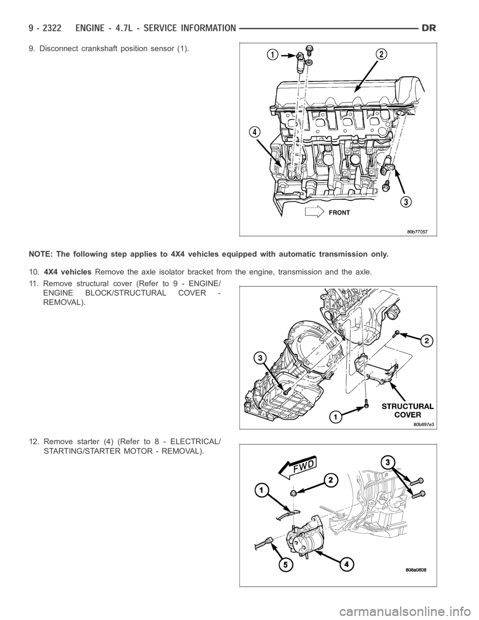
9. Disconnect crankshaft position sensor (1).
NOTE: The following step applies to 4X4vehicles equipped with automatic transmission only.
10.4X4 vehiclesRemove the axle isolator bracket from the engine, transmission and the axle.
11. Remove structural cover (Refer to 9 - ENGINE/
ENGINE BLOCK/STRUCTURAL COVER -
REMOVAL).
12. Remove starter (4) (Refer to 8 - ELECTRICAL/
STARTING/STARTER MOTOR - REMOVAL).
Page 1632 of 5267
13. Drain cooling system (Refer to 7 - COOLING - STANDARD PROCEDURE).
14. Remove torque converter bolts (Automatic Transmission Only).
15. Remove transmission to engine mounting bolts.
16. Disconnect the engine block heater power cable from the block heater, if equipped.
17. Lower vehicle.
18. Remove throttle body resonator assembly and air inlet hose.
19. Disconnect throttle and speed control cables.
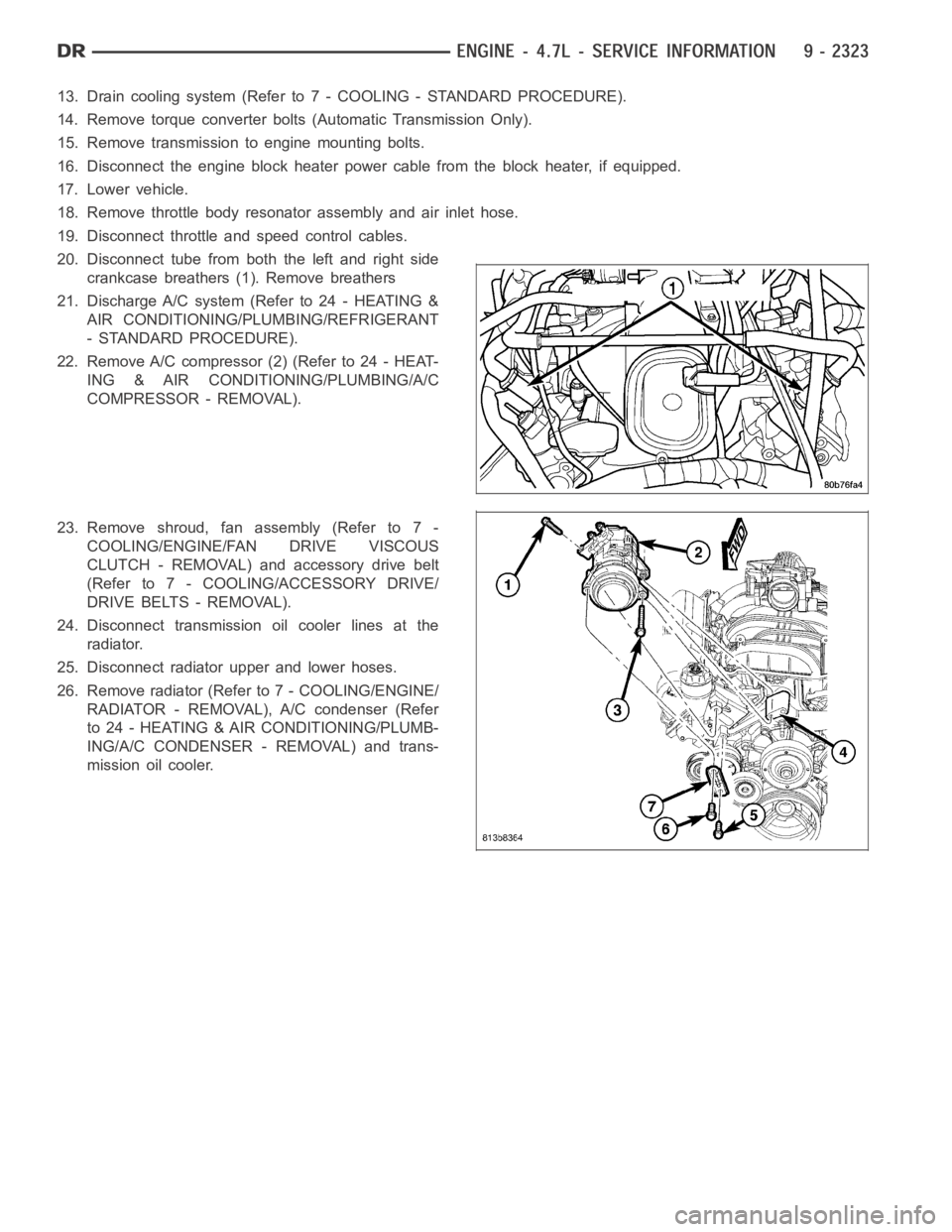
20. Disconnect tube from both the left and right side
crankcase breathers (1). Remove breathers
21. Discharge A/C system (Refer to 24 - HEATING &
AIR CONDITIONING/PLUMBING/REFRIGERANT
- STANDARD PROCEDURE).
22. Remove A/C compressor (2) (Refer to 24 - HEAT-
ING & AIR CONDITIONING/PLUMBING/A/C
COMPRESSOR - REMOVAL).
23. Remove shroud, fan assembly (Refer to 7 -
COOLING/ENGINE/FAN DRIVE VISCOUS
CLUTCH - REMOVAL) and accessory drive belt
(Refer to 7 - COOLING/ACCESSORY DRIVE/
DRIVE BELTS - REMOVAL).
24. Disconnect transmission oil cooler lines at the
radiator.
25. Disconnect radiator upper and lower hoses.
26. Remove radiator (Refer to 7 - COOLING/ENGINE/
RADIATOR - REMOVAL), A/C condenser (Refer
to 24 - HEATING & AIR CONDITIONING/PLUMB-
ING/A/C CONDENSER - REMOVAL) and trans-
mission oil cooler.
Page 1639 of 5267
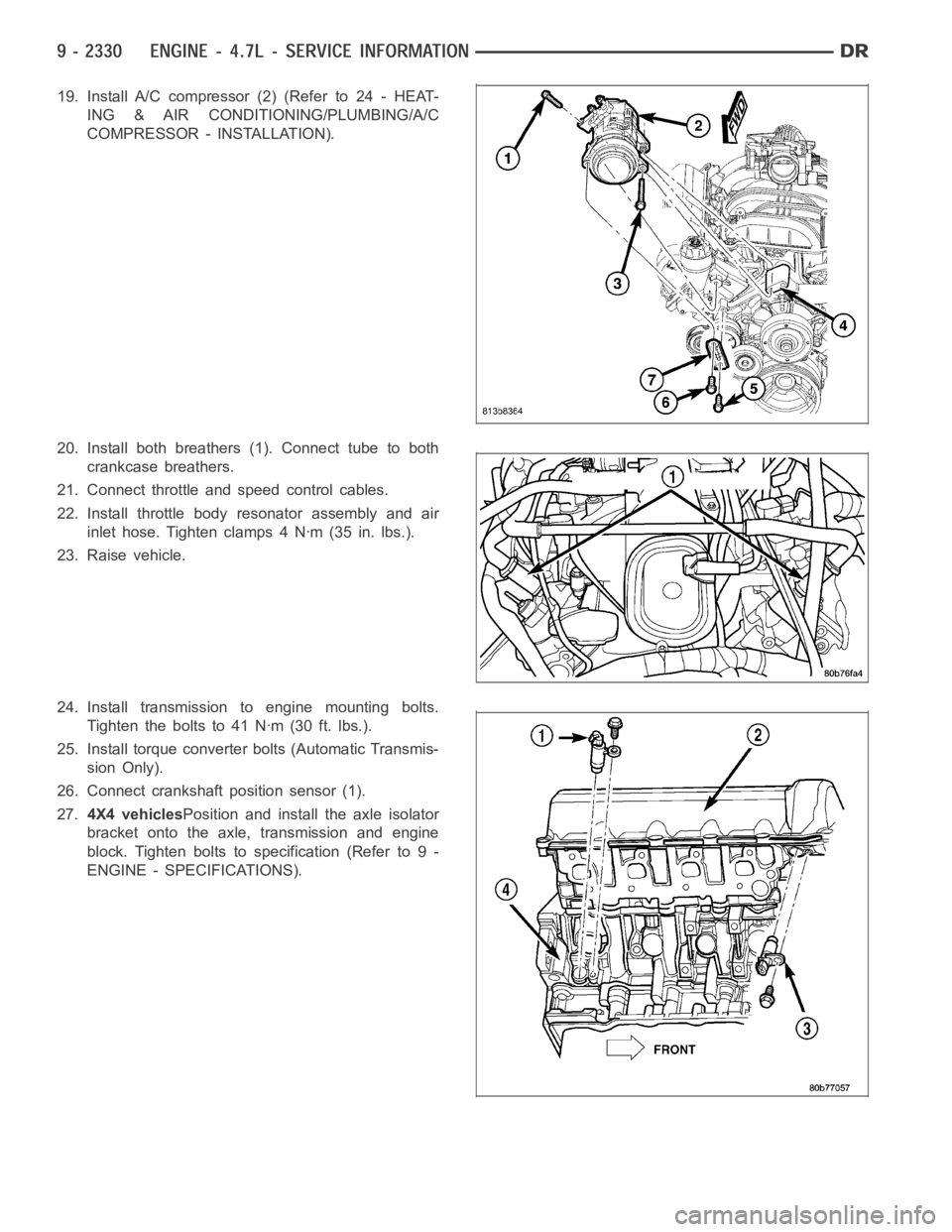
19. Install A/C compressor (2) (Refer to 24 - HEAT-
ING & AIR CONDITIONING/PLUMBING/A/C
COMPRESSOR - INSTALLATION).
20. Install both breathers (1). Connect tube to both
crankcase breathers.
21. Connect throttle and speed control cables.
22. Install throttle body resonator assembly and air
inlet hose. Tighten clamps 4 Nꞏm (35 in. lbs.).
23. Raise vehicle.
24. Install transmission to engine mounting bolts.
Tighten the bolts to 41 Nꞏm (30 ft. lbs.).
25. Install torque converter bolts (Automatic Transmis-
sion Only).
26. Connect crankshaft position sensor (1).
27.4X4 vehiclesPosition and install the axle isolator
bracket onto the axle, transmission and engine
block. Tighten bolts to specification (Refer to 9 -
ENGINE - SPECIFICATIONS).