2006 DODGE RAM SRT-10 automatic transmission
[x] Cancel search: automatic transmissionPage 1915 of 5267
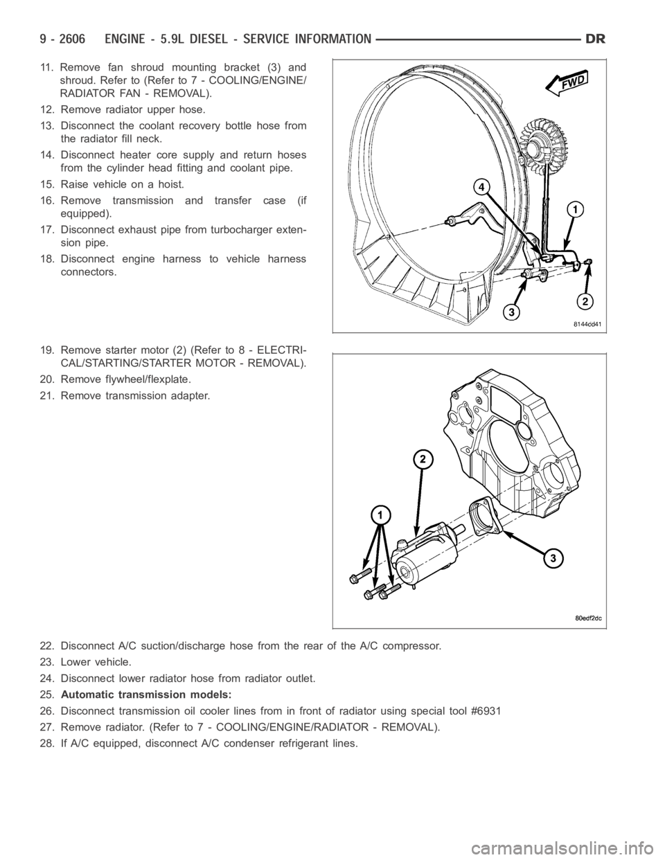
11. Remove fan shroud mounting bracket (3) and
shroud. Refer to (Refer to 7 - COOLING/ENGINE/
RADIATOR FAN - REMOVAL).
12. Remove radiator upper hose.
13. Disconnect the coolant recovery bottle hose from
the radiator fill neck.
14. Disconnect heater core supply and return hoses
from the cylinder head fitting and coolant pipe.
15. Raise vehicle on a hoist.
16. Remove transmission and transfer case (if
equipped).
17. Disconnect exhaust pipe from turbocharger exten-
sion pipe.
18. Disconnect engine harness to vehicle harness
connectors.
19. Remove starter motor (2) (Refer to 8 - ELECTRI-
CAL/STARTING/STARTER MOTOR - REMOVAL).
20. Remove flywheel/flexplate.
21. Remove transmission adapter.
22. Disconnect A/C suction/discharge hose from the rear of the A/C compressor.
23. Lower vehicle.
24. Disconnect lower radiator hose from radiator outlet.
25.Automatic transmission models:
26. Disconnect transmission oil cooler lines from in front of radiator using special tool #6931
27. Remove radiator. (Refer to 7 - COOLING/ENGINE/RADIATOR - REMOVAL).
28. If A/C equipped, disconnect A/C condenser refrigerant lines.
Page 1966 of 5267
CAMSHAFT & BEARINGS (IN BLOCK)
REMOVAL
CAMSHAFT BEARINGS
NOTE: Measure the diameter of each bore. If the camshaft bore for the cam bushing is worn beyond the
limit, install a new service bushing. Inspect the rest of the camshaft bores for damage or excessive wear.If
the bores without a bushing are worn beyond the limit, the engine must be removed for machining and
installation of service bushings. If badly worn, replace the cylinder block.
1. Remove the camshaft (Refer to 9 - ENGINE/ENGINE BLOCK/CAMSHAFT & BEARINGS (IN BLOCK) -
REMOVAL).
2. Remove the bushing from the No.1 bore.
3. Mark the cylinder block so you can align the oil hole in the cylinder blockwith the oil hole in the bushing.
CAMSHAFT
1. Disconnect both battery negative cables.
2. Recover A/C refrigerant (if A/C equipped) (Refer to 24 - HEATING & AIR CONDITIONING/PLUMBING - STAN-
DARD PROCEDURE).
3. Raise vehicle on hoist.
4. Drain engine coolant into container suitable for re-use (Refer to 7 - COOLING - STANDARD PROCEDURE).
5. Lower vehicle.
6. Remove radiator upper hose.
7. Remove viscous fan/drive/shroud assembly (Refer to 7 - COOLING/ENGINE/RADIATOR FAN - REMOVAL).
8. Disconnect the coolant recovery bottle hose from the radiator filler neck.
9. Disconnect lower radiator hose from radiator outlet.
10.Automatic Transmission models:Disconnect transmission oil cooler lines from front of radiator using Special
Tool 6931 (unless equipped with finger-release disconnect).
11. Remove radiator mounting screws and lift radiator out of engine compartment.
12. Remove upper radiator support panel.
13. If A/C equipped, disconnect A/C condenser refrigerant lines.
14. Disconnect charge air cooler piping from the cooler inlet and outlet.
15. Remove the two charge air cooler mounting bolts.
16. Remove charge air cooler (and A/C condenser if equipped) from vehicle.
17. Remove accessory drive belt (Refer to 7 - COOLING/ACCESSORY DRIVE/DRIVE BELTS - REMOVAL).
18. Remove accessory drive belt tensioner.
19. Remove the fan support/hub assembly.
20. Remove crankshaft damper and speed indicator ring (Refer to 9 - ENGINE/ENGINE BLOCK/VIBRATION
DAMPER - REMOVAL).
21. Remove the gear cover-to-housing bolts and gently pry the cover away from the housing, taking care not to mar
the sealing surfaces. Remove dust seal with cover.
22. Using Special Tool 7471–B Crankshaft Barring Tool, rotate the crankshaft to align the timing marks on the
crankshaft and the camshaft gears.
23. Remove the cylinder head cover (Refer to 9 - ENGINE/CYLINDER HEAD/CYLINDER HEAD COVER(S) -
REMOVAL).
Page 1981 of 5267
CAUTION: The seal lip and the sealing surface on
the crankshaft must be free from all oil residue to
prevent seal leaks. The crankshaft and seal sur-
faces must be completely dry when the seal is
installed. Use a soap and water solution on out-
side diameter of seal to ease assembly.
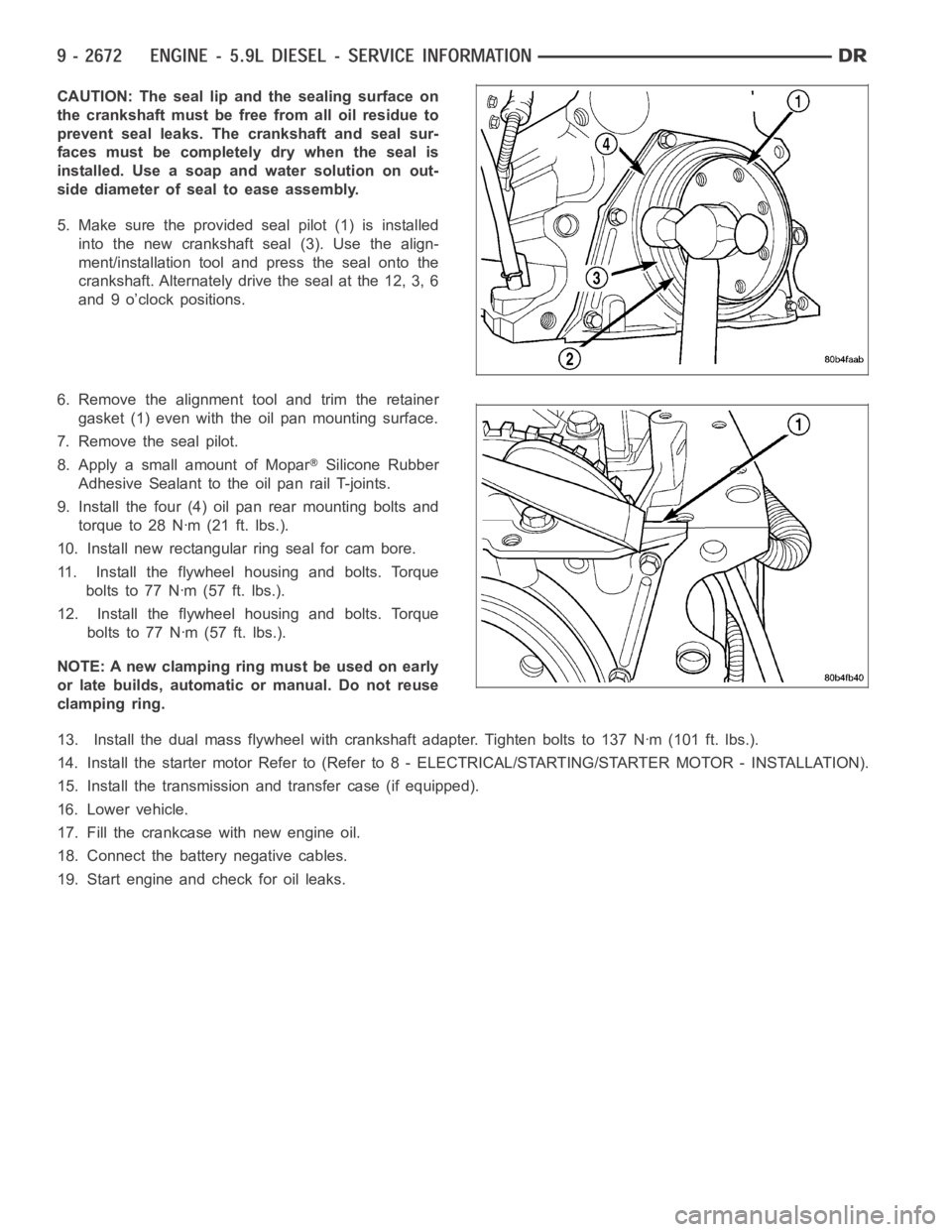
5. Make sure the provided seal pilot (1) is installed
into the new crankshaft seal (3). Use the align-
ment/installation tool and press the seal onto the
crankshaft. Alternately drive the seal at the 12, 3, 6
and 9 o’clock positions.
6. Remove the alignment tool and trim the retainer
gasket (1) even with the oil pan mounting surface.
7. Remove the seal pilot.
8. Apply a small amount of Mopar
Silicone Rubber
Adhesive Sealant to the oil pan rail T-joints.
9. Install the four (4) oil pan rear mounting bolts and
torque to 28 Nꞏm (21 ft. lbs.).
10. Install new rectangular ring seal for cam bore.
11. Install the flywheel housing and bolts. Torque
boltsto77Nꞏm(57ft.lbs.).
12. Install the flywheel housing and bolts. Torque
boltsto77Nꞏm(57ft.lbs.).
NOTE: A new clamping ring must be used on early
or late builds, automatic or manual. Do not reuse
clamping ring.
13. Install the dual mass flywheel with crankshaft adapter. Tighten boltsto 137 Nꞏm (101 ft. lbs.).
14. Install the starter motor Refer to (Refer to 8 - ELECTRICAL/STARTING/STA R T E R M O TO R - I N S TA L L AT I O N ) .
15. Install the transmission and transfer case (if equipped).
16. Lower vehicle.
17. Fill the crankcase with new engine oil.
18. Connect the battery negative cables.
19. Start engine and check for oil leaks.
Page 2005 of 5267
PA N - E N G I N E O I L
REMOVAL
1. Disconnect the battery negative cables.
2. Install engine support fixture # 8534.
3. Raise vehicle on hoist.
4. Disconnect starter cables from starter motor.
5. Remove transmission and transfer case (if equipped).
6. Remove flywheel or flexplate.
7. Remove starter motor (Refer to 8 - ELECTRICAL/STARTING/STARTER MOTOR -REMOVAL) and transmission
adapter plate assembly.
WARNING: HOT OIL CAN CAUSE PERSONAL INJURY.
8. Drain the engine oil (Refer to 9 - ENGINE/LUBRICATION/OIL - STANDARD PROCEDURE).
9. Install the oil pan drain plug if sealing surface is not damaged and tighten to 50 Nꞏm (37 ft. lbs.) torque.
10. Remove oil pan bolts, break the pan to block seal, and lower pan slightlyandremoveoilsuctiontubefasteners.
11. Remove oil pan and suction tube.
CLEANING
Remove all gasket material from the oil pan and cylinder block sealing surfaces. Extra effort may be required
around T-joint areas. Clean oil pan and flush suction tube with a suitable solvent.
INSPECTION
Inspect the oil pan, suction tube, and tube braces for cracks and damage. Replace any defective component.
Inspect the oil drain plug and drain hole threads. Inspect the oil pan sealing surface for straightness. Repair any
minor imperfections with a ball-peen hammer. Do not attempt to repair an oil pan by welding.
INSTALLATION
1. Fill the T-joint between the pan rail/gear housing and pan rail/rear seal retainer with sealant. Use MoparSilicone
Rubber Adhesive Sealant or equivalent.
2. Place suction tube in oil pan and guide them into place. Slide oil pan gasket into postion.Using a new tube to
block gasket, install and tighten the suction tube bolts by hand. Startingwith the oil pump inlet bolts, tighten the
bolts to 24 Nꞏm (18 ft. lbs.) torque. Tighten the remaining tube brace boltsto 43 Nꞏm (32 ft. lbs.) torque.
3. Starting in the center and working outward, tighten the oil pan bolts to 28Nꞏm(21ft.lbs.)torque.
4. Install the flywheel housing assembly with the starter motor attached and tighten bolts to 77 Nꞏm (57 ft. lbs.)
torque.
5. Connect starter motor cables.
NOTE: A new clamping ring must be used on early or late builds, automatic or manual. Do not reuse clamp-
ing ring.
6. Install the flywheel to crankshaft adapter. Torque to 137 Nꞏm (101 ft. lbs.).
7. Install transmission and transfer case (if equipped).
8. Lower vehicle.
9. Remove the engine support fixture # 8534.
10. Install battery negative cables.
11. Fill the crankcase with new engine oil.
12. Start engine and check for leaks. Stop engine, check oil level, and adjust, if necessary.
Page 2031 of 5267
STANDARD PROCEDURE
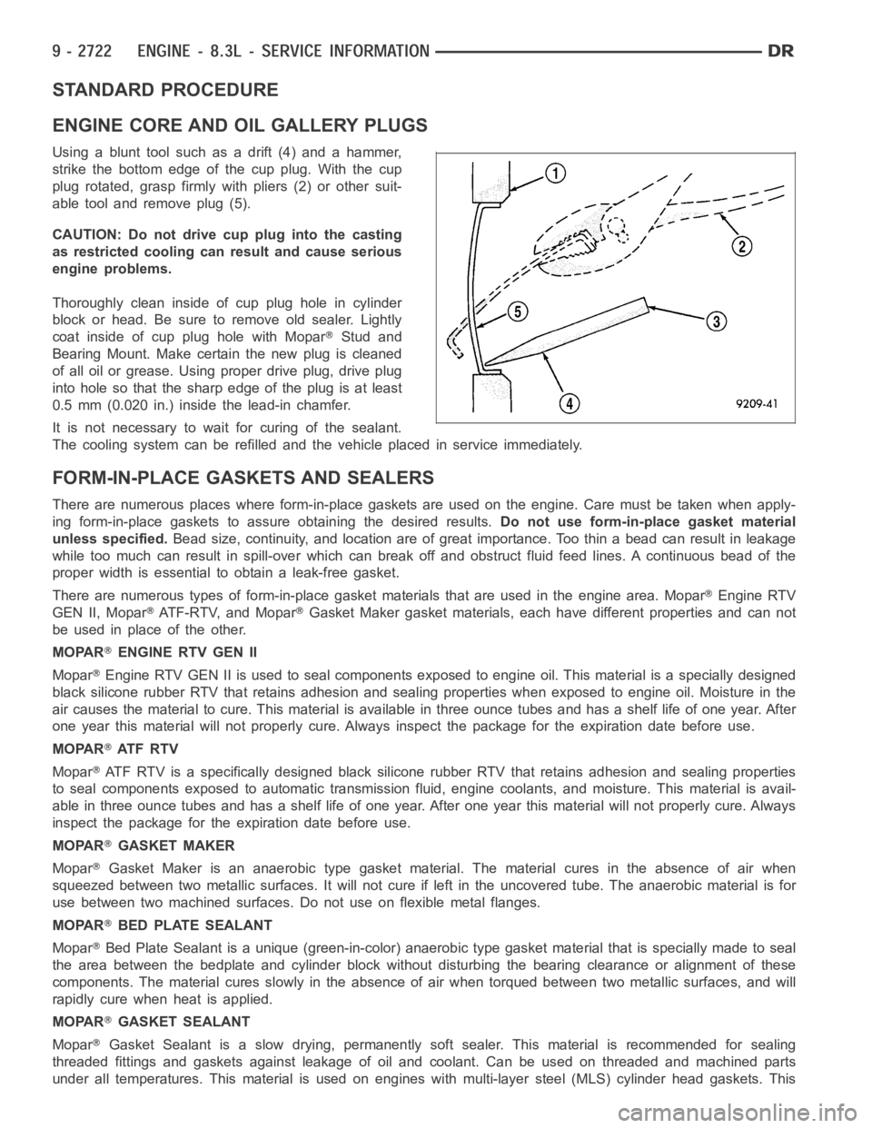
ENGINE CORE AND OIL GALLERY PLUGS
Using a blunt tool such as a drift (4) and a hammer,
strike the bottom edge of the cup plug. With the cup
plug rotated, grasp firmly with pliers (2) or other suit-
able tool and remove plug (5).
CAUTION: Do not drive cup plug into the casting
as restricted cooling can result and cause serious
engine problems.
Thoroughly clean inside of cup plug hole in cylinder
block or head. Be sure to remove old sealer. Lightly
coat inside of cup plug hole with Mopar
Stud and
Bearing Mount. Make certain the new plug is cleaned
of all oil or grease. Using proper drive plug, drive plug
into hole so that the sharp edge of the plug is at least
0.5 mm (0.020 in.) inside the lead-in chamfer.
It is not necessary to wait for curing of the sealant.
The cooling system can be refilled and the vehicle placed in service immediately.
FORM-IN-PLACE GASKETS AND SEALERS
There are numerous places where form-in-place gaskets are used on the engine. Care must be taken when apply-
ing form-in-place gaskets to assure obtaining the desired results.Do not use form-in-place gasket material
unless specified.Bead size, continuity, and location are of great importance. Too thin a bead can result in leakage
while too much can result in spill-overwhich can break off and obstruct fluid feed lines. A continuous bead of the
proper width is essential to obtain a leak-free gasket.
There are numerous types of form-in-place gasket materials that are used in the engine area. Mopar
Engine RTV
GEN II, Mopar
ATF-RTV, and MoparGasket Maker gasket materials, each have different properties and can not
be used in place of the other.
MOPAR
ENGINE RTV GEN II
Mopar
Engine RTV GEN II is used to seal components exposed to engine oil. This material is a specially designed
black silicone rubber RTV that retains adhesion and sealing properties when exposed to engine oil. Moisture in the
air causes the material to cure. This material is available in three ounce tubes and has a shelf life of one year. After
one year this material will not properly cure. Always inspect the package for the expiration date before use.
MOPAR
AT F R T V
Mopar
ATF RTV is a specifically designed black silicone rubber RTV that retains adhesion and sealing properties
to seal components exposed to automatic transmission fluid, engine coolants, and moisture. This material is avail-
able in three ounce tubes and has a shelf life of one year. After one year thismaterial will not properly cure. Always
inspect the package for the expiration date before use.
MOPAR
GASKET MAKER
Mopar
Gasket Maker is an anaerobic type gasket material. The material cures in the absence of air when
squeezed between two metallic surfaces. It will not cure if left in the uncovered tube. The anaerobic material is for
use between two machined surfaces. Do not use on flexible metal flanges.
MOPAR
BED PLATE SEALANT
Mopar
Bed Plate Sealant is a unique (green-in-color) anaerobic type gasket material that is specially made to seal
the area between the bedplate and cylinder block without disturbing the bearing clearance or alignment of these
components. The material cures slowly in the absence of air when torqued between two metallic surfaces, and will
rapidly cure when heat is applied.
MOPAR
GASKET SEALANT
Mopar
Gasket Sealant is a slow drying, permanently soft sealer. This material isrecommended for sealing
threaded fittings and gaskets against leakage of oil and coolant. Can be used on threaded and machined parts
under all temperatures. This material is used on engines with multi-layersteel (MLS) cylinder head gaskets. This
Page 2315 of 5267
higher altitude, because the air density changes with altitude. It will also help to correct for varying barometric pres-
sure. Barometric pressure and altitude have a direct inverse correlation; as altitude goes up, barometric goes down.
At key-on, the PCM powers up and looks at MAP voltage, and based upon the voltage it sees, it knows the current
barometric pressure (relative to altitude). Once the engine starts, the PCM looks at the voltage again, continuously
every 12 milliseconds, and compares the current voltage to what it was at key-on. The difference between current
voltage and what it was at key-on, is manifold vacuum.
During key-on (engine not running) the sensor reads (updates) barometricpressure. A normal range can be
obtained by monitoring a known good sensor.
As the altitude increases, the air becomes thinner (less oxygen). If a vehicleisstartedanddriventoaverydifferent
altitude than where it was at key-on, the barometric pressure needs to be updated. Any time the PCM sees Wide
Open Throttle (WOT), based upon Throttle Position Sensor (TPS) angle and RPM, it will update barometric pressure
in the MAP memory cell. With periodic updates, the PCM can make its calculations more effectively.
The PCM uses the MAP sensor input to aid in calculating the following:
Manifold pressure
Barometric pressure
Engine load
Injector pulse-width
Spark-advance programs
Shift-point strategies (certain automatic transmissions only)
Idle speed
Decel fuel shutoff
The MAP sensor signal is provided from asingle piezoresistive element located in the center of a diaphragm. The
element and diaphragm are both made ofsilicone. As manifold pressure changes, the diaphragm moves causing
the element to deflect, which stresses the silicone. When silicone is exposed to stress, its resistance changes. As
manifold vacuum increases, the MAP sensor input voltage decreases proportionally. The sensor also contains elec-
tronics that condition the signal and provide temperature compensation.
The PCM recognizes a decrease in manifold pressure by monitoring a decrease in voltage from the reading stored
in the barometric pressure memory cell. The MAP sensor is a linear sensor; meaning as pressure changes, voltage
changes proportionately. The range of voltage output from the sensor is usually between 4.6 volts at sea level to as
low as 0.3 volts at 26 in. of Hg. Barometric pressure is the pressure exertedby the atmosphere upon an object. At
sea level on a standard day, no storm, barometric pressure is approximately 29.92 in Hg. For every 100 feet of
altitude, barometric pressure drops 0.10 in. Hg. If a storm goes through, it can change barometric pressure from
what should be present for that altitude. You should know what the average pressure and corresponding barometric
pressure is for your area.
Page 2336 of 5267
OPERATION
The 5.7L V-8 engine does not use a separate Throttle Position Sensor (TPS) on the throttle body.
The 3-wire TPS provides the Powertrain Control Module (PCM) with an input signal (voltage) that represents the
throttle blade position of the throttle body. The sensor is connected to the throttle blade shaft. As the position of the
throttle blade changes, the output voltage of the TPS changes.
The PCM supplies approximately 5 volts to the TPS. The TPS output voltage (input signal to the PCM) represents
the throttle blade position. The PCM receives an input signal voltage fromthe TPS. This will vary in an approximate
range of from .26 volts at minimum throttle opening (idle), to 4.49 volts atwide open throttle. Along with inputs from
other sensors, the PCM uses the TPS input to determine current engine operating conditions. In response to engine
operating conditions, the PCM will adjust fuel injector pulse width and ignition timing.
The PCM needs to identify the actions and position of the throttle blade at all times. This information is needed to
assist in performing the following calculations:
Ignition timing advance
Fuel injection pulse-width
Idle (learned value or minimum TPS)
Off-idle (0.06 volt)
Wide Open Throttle (WOT) open loop (2.608 volts above learned idle voltage)
Deceleration fuel lean out
Fuel cutoff during cranking at WOT (2.608 volts above learned idle voltage)
A/C WOT cutoff (certain automatic transmissions only)
REMOVAL
3.7L V6
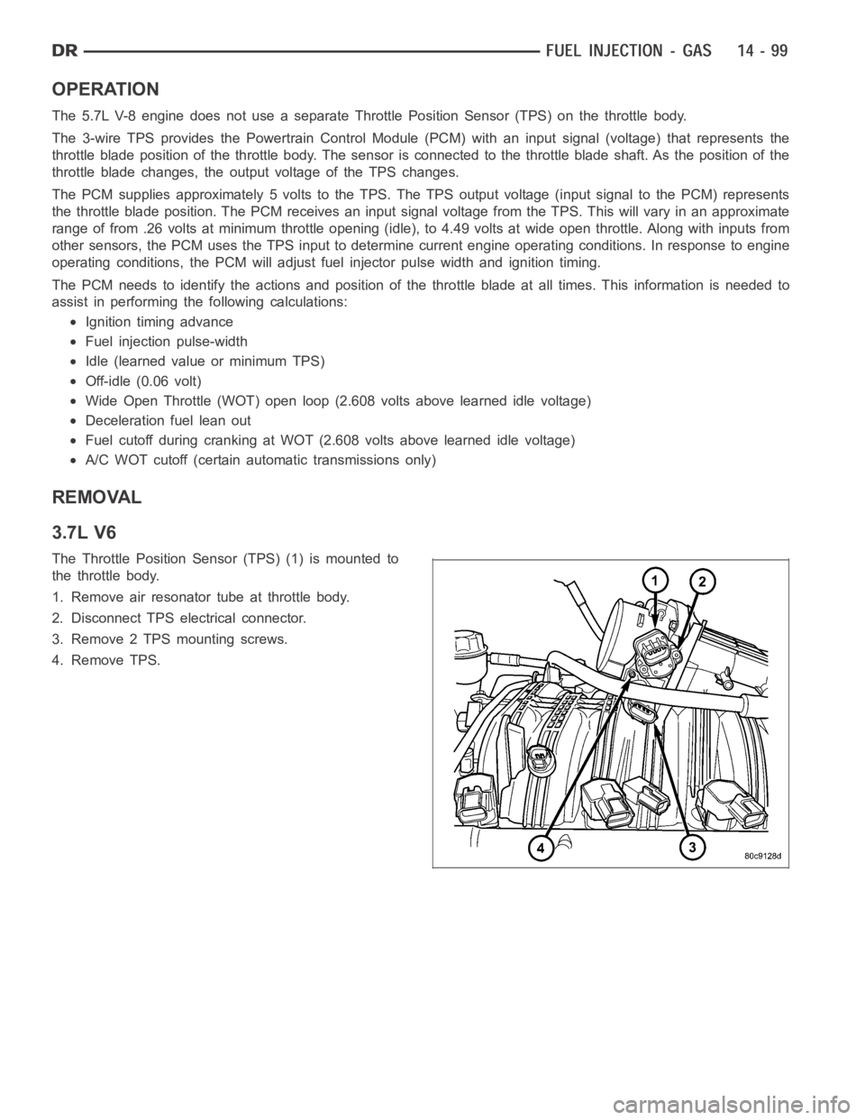
The Throttle Position Sensor (TPS) (1) is mounted to
the throttle body.
1. Remove air resonator tube at throttle body.
2. Disconnect TPS electrical connector.
3. Remove 2 TPS mounting screws.
4. Remove TPS.
Page 2413 of 5267
COLUMN
DESCRIPTION
DESCRIPTION
NOTE: The steering column on vehicles with an automatic transmission may not be equipped with an inter-
nal locking shaft that allows the ignition key cylinder to be locked with the key. Alternative methods of lock-
ing the steering wheel for service will have to be used.
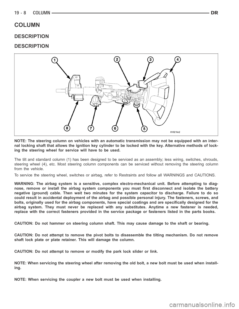
The tilt and standard column (1) has been designed to be serviced as an assembly; less wiring, switches, shrouds,
steering wheel (4), etc. Most steering column components can be serviced without removing the steering column
from the vehicle.
To service the steering wheel, switches or airbag, refer to Restraints andfollow all WARNINGS and CAUTIONS.
WARNING: The airbag system is a sensitive, complex electro-mechanical unit. Before attempting to diag-
nose, remove or install the airbag system components you must first disconnect and isolate the battery
negative (ground) cable. Then wait two minutes for the system capacitor todischarge. Failure to do so
could result in accidental deployment of the airbag and possible personalinjury. The fasteners, screws, and
bolts, originally used for the airbag components, have special coatings and are specifically designed for the
airbag system. They must never be replaced with any substitutes. Anytime anew fastener is needed,
replace with the correct fasteners provided in the service package or fasteners listed in the parts books.
CAUTION: Do not hammer on steering column shaft. This may cause damage to the shaft or bearing.
CAUTION: Do not attempt to remove the pivot bolts to disassemble the tilting mechanism. Do not remove
shaft lock plate or plate retainer. This will damage the column.
CAUTION: Do not attempt to remove or modify the park lock slider or link.
NOTE: When servicing the steering wheel after removing the old bolt, a new bolt must be used when install-
ing.
NOTE: When servicing the coupler a new bolt must be used when installing.