2006 DODGE RAM SRT-10 fuel cap
[x] Cancel search: fuel capPage 2241 of 5267
OPERATION
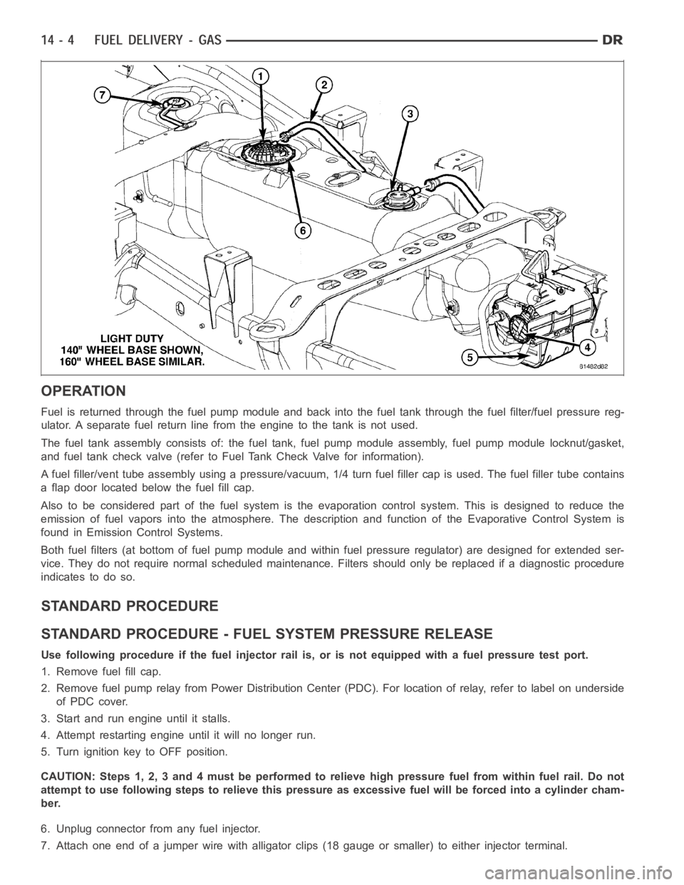
Fuel is returned through the fuel pump module and back into the fuel tank through the fuel filter/fuel pressure reg-
ulator. A separate fuel return line from the engine to the tank is not used.
The fuel tank assembly consists of: the fuel tank, fuel pump module assembly, fuel pump module locknut/gasket,
and fuel tank check valve (refer to Fuel Tank Check Valve for information).
A fuel filler/vent tube assembly using apressure/vacuum,1/4 turn fuel filler cap is used. The fuel filler tube contains
a flap door located below the fuel fill cap.
Also to be considered part of the fuelsystem is the evaporation control system. This is designed to reduce the
emission of fuel vapors into the atmosphere. The description and functionof the Evaporative Control System is
found in Emission Control Systems.
Both fuel filters (at bottom of fuel pump module and within fuel pressure regulator) are designed for extended ser-
vice. They do not require normal scheduled maintenance. Filters should only be replaced if a diagnostic procedure
indicates to do so.
STANDARD PROCEDURE
STANDARD PROCEDURE - FUEL SYSTEM PRESSURE RELEASE
Use following procedure if the fuel injector rail is, or is not equipped with a fuel pressure test port.
1. Remove fuel fill cap.
2. Remove fuel pump relay from Power Distribution Center (PDC). For location of relay, refer to label on underside
of PDC cover.
3. Start and run engine until it stalls.
4. Attempt restarting engine until it will no longer run.
5. Turn ignition key to OFF position.
CAUTION: Steps 1, 2, 3 and 4 must be performed to relieve high pressure fuel from within fuel rail. Do not
attempt to use following steps to relieve this pressure as excessive fuel will be forced into a cylinder cham-
ber.
6. Unplug connector from any fuel injector.
7. Attach one end of a jumper wire with alligator clips (18 gauge or smaller)to either injector terminal.
Page 2242 of 5267

8. Connect other end of jumper wire to positive side of battery.
9. Connect one end of a second jumper wire to remaining injector terminal.
CAUTION: Powering an injector for more than a few seconds will permanentlydamage the injector.
10. Momentarily touch other end of jumper wire to negative terminal of battery for no more than a few seconds.
11. Place a rag or towel below fuel line quick-connect fitting at fuel rail.
12. Disconnect quick-connect fitting at fuel rail. Refer to Quick-Connect Fittings.
13. Return fuel pump relay to PDC.
14. One or more Diagnostic Trouble Codes (DTC’s) may have been stored in PCMmemory due to fuel pump relay
removal. The DRB
scantoolmustbeusedtoeraseaDTC.
STANDARD PROCEDURE - DRAINING FUEL TANK - EXCEPT DIESEL
WARNING: The fuel system may be under constant fuel pressure even with the engine off. This pressure
must be released before servicing fuel tank.
Two different procedures may be used to drain fuel tank: through the fuel fill fitting on tank, or using a diagnostic
scan tool to activate the fuel pump relay. Due to a one-way check valve installed into the fuel fill opening fitting at
the tank, the tank cannot be drained conventionally at the fill cap.
The quickest draining procedure involves removing the rubber fuel fill hose at the fuel tank.
As an alternative procedure, the electric fuel pump may be activated allowingtanktobedrainedatfuelrailcon-
nection. Refer to diagnostic scan tool for fuel pump activation procedures. Before disconnecting fuel line at fuel rail,
release fuel pressure. Refer to the Fuel System Pressure Release Procedure for procedures. Attach end of special
test hose tool number 6631 or 6539 at fuel rail disconnection (tool number 6631isusedon5/16”fuellineswhile
tool number 6539 is used on 3/8” fuel lines). Position opposite end of this hose tool to an approved gasoline drain-
ing station. Activate fuel pump and drain tank until empty.
If electric fuel pump is not operating, fuel must be drained through fuel fill fitting at tank. Refer to following proce-
dures.
1. Release fuel system pressure.
2. Raise vehicle.
3. Thoroughly clean area around fuel fill fitting and rubber fuel fill hoseat tank.
4. If vehicle is equipped with 4 doors and a 6 foot (short) box, remove left-rear tire/wheel.
5. Loosen clamp and disconnect rubber fuel fill hose at tank fitting. Usingan approved gas holding tank, drain fuel
tank through this fitting.
SPECIFICATIONS
FUEL SYSTEM PRESSURE
58 psi +/- 2 psi
TORQUE - EXCEPT DIESEL
DESCRIPTION N-m Ft. Lbs. In. Lbs.
Accelerator Pedal Bracket
Mounting12 - 105
Accelerator Pedal Position
Sensor Bracket-to-Battery
Tray Bolts3-30
Crankshaft Position
Sensor - 3.7L28 21 -
Crankshaft Position
Sensor - 4.7L28 21 -
Page 2247 of 5267
SENSOR - FUEL LEVEL SENDING UNIT
DESCRIPTION
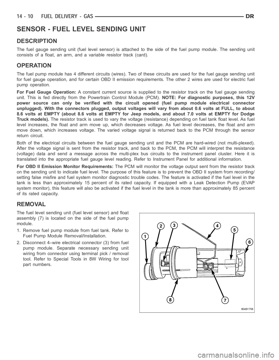
The fuel gauge sending unit (fuel level sensor) is attached to the side of the fuel pump module. The sending unit
consists of a float, an arm, and a variable resistor track (card).
OPERATION
The fuel pump module has 4 different circuits (wires). Two of these circuits are used for the fuel gauge sending unit
for fuel gauge operation, and for certain OBD II emission requirements. The other 2 wires are used for electric fuel
pump operation.
For Fuel Gauge Operation:A constant current source is supplied to the resistor track on the fuel gauge sending
unit. This is fed directly from the Powertrain Control Module (PCM).NOTE: For diagnostic purposes, this 12V
power source can only be verified with the circuit opened (fuel pump moduleelectrical connector
unplugged). With the connectors plugged, output voltages will vary from about 0.6 volts at FULL, to about
8.6 volts at EMPTY (about 8.6 volts at EMPTY for Jeep models, and about 7.0 volts at EMPTY for Dodge
Truck models).The resistor track is used to vary the voltage (resistance) depending on fuel tank float level. As fuel
level increases, the float and arm move up, which decreases voltage. As fuel level decreases, the float and arm
move down, which increases voltage. The varied voltage signal is returnedback to the PCM through the sensor
return circuit.
Both of the electrical circuits between the fuel gauge sending unit and thePCM are hard-wired (not multi-plexed).
After the voltage signal is sent from the resistor track, and back to the PCM, the PCM will interpret the resistance
(voltage) data and send a message across the multi-plex bus circuits to theinstrument panel cluster. Here it is
translated into the appropriate fuel gauge level reading. Refer to Instrument Panel for additional information.
For OBD II Emission Monitor Requirements:The PCM will monitor the voltage output sent from the resistor track
on the sending unit to indicate fuel level. The purpose of this feature is toprevent the OBD II system from recording/
setting false misfire and fuel systemmonitor diagnostic trouble codes. The feature is activated if the fuel level in the
tank is less than approximately 15 percent of its rated capacity. If equipped with a Leak Detection Pump (EVAP
system monitor), this feature will also be activated if the fuel level in the tank is more than approximately 85 percent
of its rated capacity.
REMOVAL
The fuel level sending unit (fuel level sensor) and float
assembly (7) is located on the side of the fuel pump
module.
1. Remove fuel pump module from fuel tank. Refer to
Fuel Pump Module Removal/Installation.
2. Disconnect 4–wire electrical connector (3) from fuel
pump module. Separate necessary sending unit
wiring from connector using terminal pick / removal
tool. Refer to Special Tools in 8W Wiring for tool
part numbers.
Page 2259 of 5267
RAIL - FUEL
DESCRIPTION
The fuel injector rail is used to mount the fuel injectors to the engine.
OPERATION
High pressure from the fuel pump is routed to the fuel rail. The fuel rail then supplies the necessary fuel to each
individual fuel injector.
A quick-connect fitting with a safety latch clip is used to attach the fuel linetothefuelrail.
The fuel rail is not repairable.
CAUTION: The left and right sections of the fuel rail are connected with either a flexible connecting hose, or
joints. Do not attempt to separate the rail halves at these connecting hoseor joints. Due to the design of
the connecting hose or joint, it does not use any clamps. Never attempt to install a clamping device of any
kind to the hose or joint. When removing the fuel rail assembly for any reason, be careful not to bend or
kink the connecting hose or joint.
REMOVAL
3.7L V-6
WARNING: The fuel system is under constant pressure even with engine off. Before servicing fuel rail, fuel
system pressure must be released.
CAUTION: The left and right fuel rails are replaced as an assembly. Do not attempt to separate rail halves
at connector tubes. Due to design of tubes, it does not use any clamps. Neverattempt to install a clamping
device of any kind to tubes. When removing fuel rail assembly for any reason, be careful not to bend or
kink tubes.
1. Remove fuel tank filler tube cap.
2. Perform Fuel System Pressure Release Procedure.
(Refer to 14 - FUEL SYSTEM/FUEL DELIVERY -
STANDARD PROCEDURE)
3. Remove negative battery cable at battery.
4. Remove air duct at throttle body air box.
5. Remove air box at throttle body.
6. Remove air resonator mounting bracket at front of
throttle body (2 bolts).
7. Disconnect fuel line latch clip and fuel line at fuel
rail. A special tool will be necessary for fuel line
disconnection. (Refer to 14 - FUEL SYSTEM/FUEL
DELIVERY/QUICK CONNECT FITTING - STAN-
DARD PROCEDURE)
8. Remove necessary vacuumlines at throttle body.
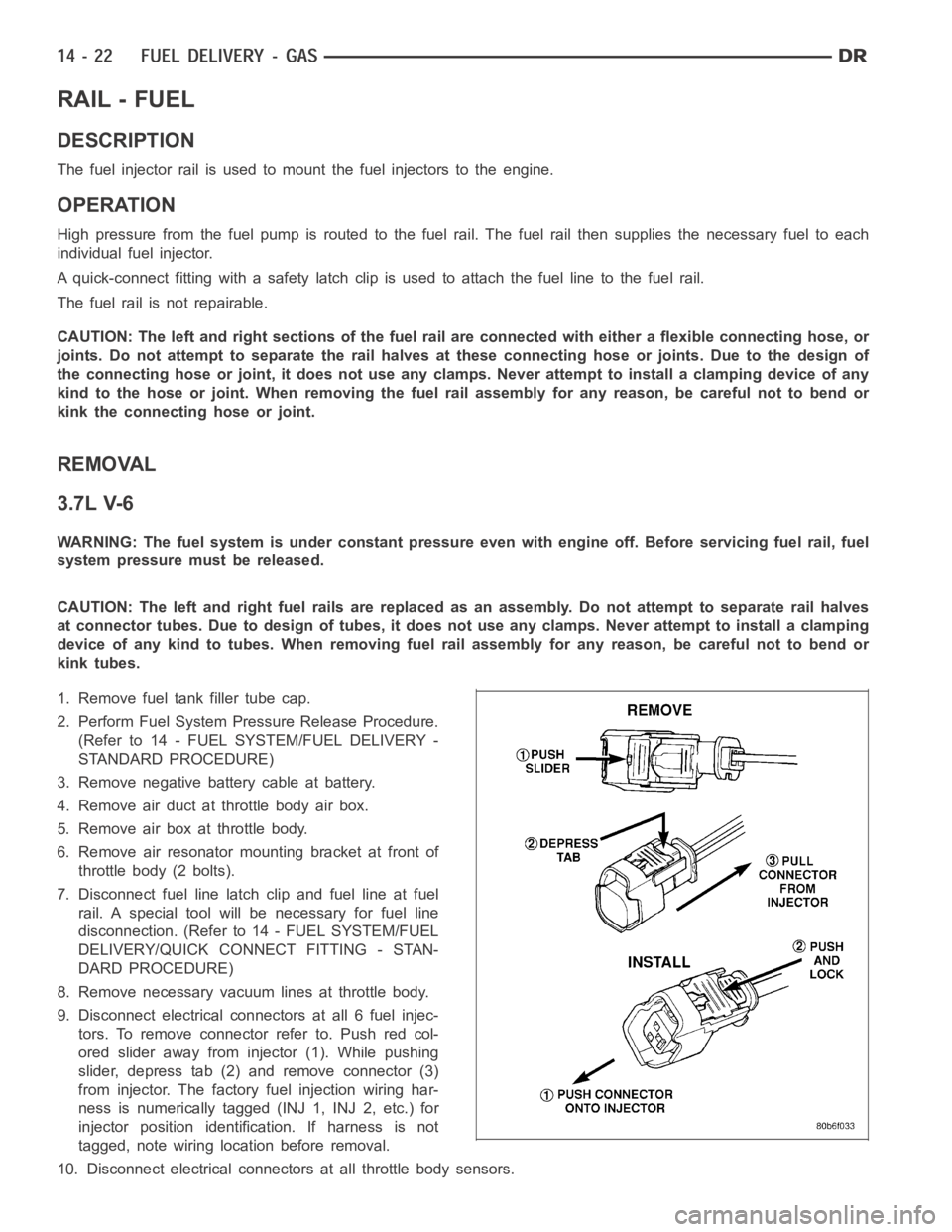
9. Disconnect electrical connectors at all 6 fuel injec-
tors. To remove connector refer to. Push red col-
ored slider away from injector (1). While pushing
slider, depress tab (2) and remove connector (3)
from injector. The factory fuel injection wiring har-
ness is numerically tagged (INJ 1, INJ 2, etc.) for
injector position identification. If harness is not
tagged, note wiring location before removal.
10. Disconnect electrical connectors at all throttle body sensors.
Page 2260 of 5267
11. Remove 6 ignition coils. (Refer to 8 - ELECTRICAL/IGNITION CONTROL/IGNITION COIL - REMOVAL)
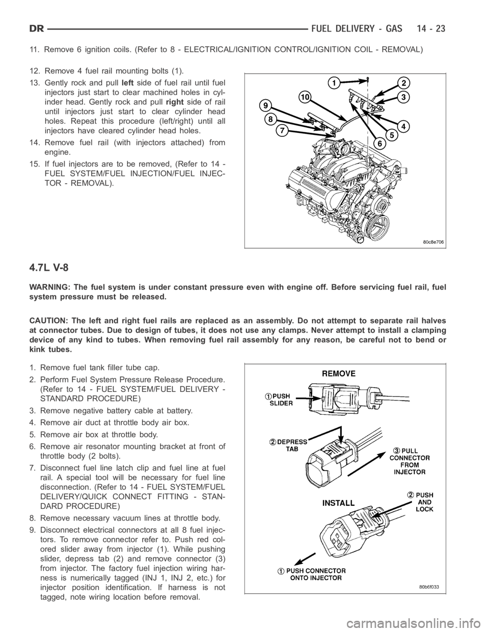
12. Remove 4 fuel rail mounting bolts (1).
13. Gently rock and pullleftside of fuel rail until fuel
injectors just start to clear machined holes in cyl-
inder head. Gently rock and pullrightside of rail
until injectors just start to clear cylinder head
holes. Repeat this procedure (left/right) until all
injectors have cleared cylinder head holes.
14. Remove fuel rail (with injectors attached) from
engine.
15. If fuel injectors are to be removed, (Refer to 14 -
FUEL SYSTEM/FUEL INJECTION/FUEL INJEC-
TOR - REMOVAL).
4.7L V-8
WARNING: The fuel system is under constant pressure even with engine off. Before servicing fuel rail, fuel
system pressure must be released.
CAUTION: The left and right fuel rails are replaced as an assembly. Do not attempt to separate rail halves
at connector tubes. Due to design of tubes, it does not use any clamps. Neverattempt to install a clamping
device of any kind to tubes. When removing fuel rail assembly for any reason, be careful not to bend or
kink tubes.
1. Remove fuel tank filler tube cap.
2. Perform Fuel System Pressure Release Procedure.
(Refer to 14 - FUEL SYSTEM/FUEL DELIVERY -
STANDARD PROCEDURE)
3. Remove negative battery cable at battery.
4. Remove air duct at throttle body air box.
5. Remove air box at throttle body.
6. Remove air resonator mounting bracket at front of
throttle body (2 bolts).
7. Disconnect fuel line latch clip and fuel line at fuel
rail. A special tool will be necessary for fuel line
disconnection. (Refer to 14 - FUEL SYSTEM/FUEL
DELIVERY/QUICK CONNECT FITTING - STAN-
DARD PROCEDURE)
8. Remove necessary vacuumlines at throttle body.
9. Disconnect electrical connectors at all 8 fuel injec-
tors. To remove connector refer to. Push red col-
ored slider away from injector (1). While pushing
slider, depress tab (2) and remove connector (3)
from injector. The factory fuel injection wiring har-
ness is numerically tagged (INJ 1, INJ 2, etc.) for
injector position identification. If harness is not
tagged, note wiring location before removal.
Page 2262 of 5267
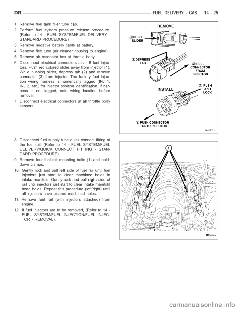
1. Remove fuel tank filler tube cap.
2. Perform fuel system pressure release procedure.
(Refer to 14 - FUEL SYSTEM/FUEL DELIVERY -
STANDARD PROCEDURE)
3. Remove negative battery cable at battery.
4. Remove flex tube (air cleaner housing to engine).
5. Remove air resonator box at throttle body.
6. Disconnect electrical connectors at all 8 fuel injec-
tors. Push red colored slider away from injector (1).
While pushing slider, depress tab (2) and remove
connector (3) from injector. The factory fuel injec-
tion wiring harness is numerically tagged (INJ 1,
INJ 2, etc.) for injector position identification. If har-
ness is not tagged, note wiring location before
removal.
7. Disconnect electrical connectors at all throttle body
sensors.
8. Disconnect fuel supply tube quick connect fitting at
the fuel rail, (Refer to14 - FUEL SYSTEM/FUEL
DELIVERY/QUICK CONNECT FITTING - STAN-
DARD PROCEDURE).
9. Remove four fuel rail mounting bolts (1) and hold-
down clamps.
10. Gently rock and pullleftside of fuel rail until fuel
injectors just start to clear machined holes in
intake manifold. Gently rock and pullrightside of
rail until injectors just start to clear intake manifold
head holes. Repeat this procedure (left/right) until
all injectors have cleared machined holes.
11. Remove fuel rail (with injectors attached) from
engine.
12. If fuel injectors are to be removed, (Refer to 14 -
FUEL SYSTEM/FUEL INJECTION/FUEL INJEC-
TOR - REMOVAL).
Page 2342 of 5267
FUEL DELIVERY - DIESEL
DESCRIPTION - DIESEL FUEL SYSTEM
WARNING: High-pressure fuel lines deliver diesel
fuel under extreme pressure from the injection
pump to the fuel injectors. This may be as high as
160,000 kpa (23,206 psi). Use extreme caution
when inspecting for high-pressure fuel leaks.
Inspect for high-pressure fuel leaks with a sheet of
cardboard. High fuel injection pressure can cause
personal injury if contact is made with the skin.
The fuel system used on the Cummins engine is an electronically controlled, Bosch HPCR (High-Pressure Common
Rail) system. The HPCR system consists of five main components:
Electric Fuel Transfer (lift) Pump Located in the Fuel Tank
Fuel Pump/Gear Pump (attached to fuel injection pump)
High-Pressure Fuel Injection Pump
Fuel Injection Rail
Fuel Injectors
Also to be considered as part of the overall fuel system are:
Accelerator Pedal
Air Cleaner Housing/Element
Check Valve Banjo Fitting at Rear of Cylinder Head
Fuel Connector Tubes
Fuel Drain Manifold (passage)
Fuel Drain Valve (at filter)
Fuel Filter/Water Separator
Fuel Heater
Fuel Heater Relay
Fuel Transfer Pump Relay
Fuel Level (gauge) Sending Unit
Fuel Pressure Limiting Valve
Fuel Tank
Fuel Tank Module (containing a fuel gauge sending unit, separate fuel filter located at bottom of tank module,
and fuel transfer pump)
Fuel Tank Filler/Vent Tube Assembly
Fuel Tank Filler Tube Cap
Fuel Tubes/Lines/Hoses
High-Pressure Fuel Injector Lines
In-Tank Fuel Filter (at bottom of fuel tank module)
Low-Pressure Fuel Supply Lines
Low-Pressure Fuel Return Lines
Overflow Valve
Quick-Connect Fuel Line Fittings
Accelerator Pedal Position Sensor (APPS) Located in Cab
Water Draining (maintenance)
Water-In-Fuel (WIF) Sensor
Screened Banjo Bolt (22)
The fuel injection pump supplies high pressure to the fuel rail independent of engine speed. This high pressure fuel
is then accumulated in the fuel rail. High pressure fuel is constantly supplied to the injectors by the fuel rail. The
Engine Control Module (ECM) controls the fueling and timing of the engine by actuating the injectors.
Page 2343 of 5267
Fuel enters the system from the electric fuel transfer (lift) pump, which is located inside of the fuel tank and attached
to the fuel tank module (the fuel transfer pump is no longer attached to the engine). Fuel is forced through the fuel
filter element and then enters the Fuel Pump/Gear Pump, which is attached to the rear of the fuel injection pump.
The Fuel Pump/Gear Pump is a low-pressure pump and produce pressures ranging from 551.5 kpa (80 psi) to 1241
kpa (180) psi. Fuel then enters the fuel injection pump. Low pressure fuel is then supplied to the FCA (Fuel Control
Actuator).
The FCA is an electronically controlled solenoid valve. The ECM controls the amount of fuel that enters the high-
pressure pumping chambers by opening and closing the FCA based on a demanded fuel pressure. The FPS (Fuel
Pressure Sensor) on the fuel rail monitors the actual fuel pressure and provides it as an input to the ECM. When
the actuator is opened, the maximum amount of fuel is being supplied to the fuel injection pump. Any fuel that does
not enter the injection pump is directed to the overflow valve. The overflow valve regulates how much excess fuel
is used for lubrication of the pump and how much is returned to the tank through the drain manifold.
Fuel entering the injection pump is pressurized to between 300-1600 bar (4351-23,206 psi) by three radial pumping
chambers. The pressurized fuel is then supplied to the fuel rail.
STANDARD PROCEDURE
WATER DRAINING AT FUEL FILTER
Refer to Fuel Filter/Water Separatorremoval/installation for procedures.
CLEANING FUEL SYSTEM PARTS
CAUTION: Cleanliness cannot be overemphasized when handling or replacingdieselfuelsystemcompo-
nents. This especially includes the fuel injectors, high-pressure fuel lines and fuel injection pump. Very tight
tolerances are used with these parts. Dirt contamination could cause rapid part wear and possible plugging
of fuel injector nozzle tip holes. This in turn could lead to possible engine misfire. Always wash/clean any
fuel system component thoroughly before disassembly and then air dry. Capor cover any open part after
disassembly. Before assembly, examine each part for dirt, grease or othercontaminants and clean if nec-
essary. When installing new parts, lubricate them with clean engine oil orclean diesel fuel only.
FUEL SYSTEM PRIMING
A certain amount of air becomes trappedin the fuel system when fuel system components on the supply and/or
high-pressure side are serviced or replaced. Fuel system priming is accomplished using the electric fuel transfer (lift)
pump.
Servicing or replacing fuel system components will not require fuel systempriming.
The fuel transfer (lift) pump is self-priming: When the key is first turnedon (without cranking engine), the pump
operates for approximately 1 to 2 second and then shuts off (Note: When ambient temperatures are cold enough to
cause the intake air heaters to operate, the fuel lift pump will operate during the entire intake air pre-heat cycle).
The pump will also operate for up to 25 seconds after the starter is quickly engaged, and then disengaged without
allowing the engine to start. The pump shuts off immediately if the key is onand the engine stops running.
1. Turn key to CRANK position and quickly release key to ON position before engine starts. This will operate fuel
transfer pump for approximately 25 seconds.
2. Crank engine. If the engine does not start after 25 seconds, turn key to OFF position, and leave it off for at least
5 seconds. Repeat previous step until engine starts.
3. Fuel system priming is now completed.
4. Attempt to start engine. If engine will not start, proceed to following steps.When engine does start, it may run
erratically and be noisy for a few minutes. This is a normal condition.
CAUTION: Do not engage the starter motor for more than 30 seconds at a time. Allow two minutes between
cranking intervals.
5. Perform previous fuel priming procedure steps using fuel transfer pump. Be sure fuel is present at fuel tank.
6. Crank the engine for 30 seconds at a time to allow fuel system to prime.