2006 DODGE RAM SRT-10 fuel cap
[x] Cancel search: fuel capPage 1761 of 5267
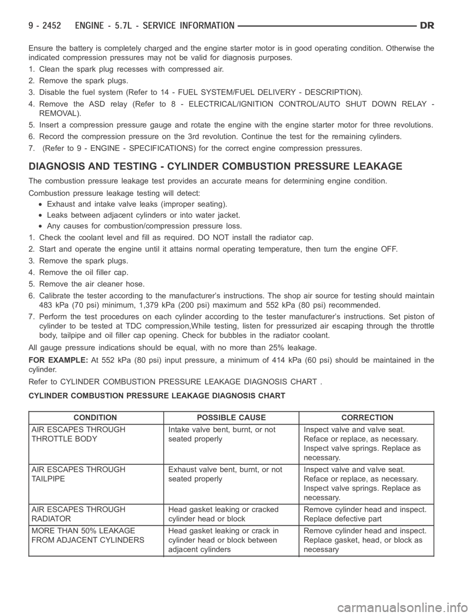
Ensurethebatteryiscompletelychargedandtheenginestartermotorisingood operating condition. Otherwise the
indicated compression pressures may not be valid for diagnosis purposes.
1. Clean the spark plug recesses with compressed air.
2. Remove the spark plugs.
3. Disable the fuel system (Refer to 14 - FUEL SYSTEM/FUEL DELIVERY - DESCRIPTION).
4. Remove the ASD relay (Refer to 8 - ELECTRICAL/IGNITION CONTROL/AUTO SHUTDOWNRELAY-
REMOVAL).
5. Insert a compression pressure gauge and rotate the engine with the engine starter motor for three revolutions.
6. Record the compression pressure on the 3rd revolution. Continue the test for the remaining cylinders.
7. (Refer to 9 - ENGINE - SPECIFICATIONS) for the correct engine compression pressures.
DIAGNOSIS AND TESTING - CYLINDERCOMBUSTION PRESSURE LEAKAGE
The combustion pressure leakage test provides an accurate means for determining engine condition.
Combustion pressure leakage testing will detect:
Exhaust and intake valve leaks (improper seating).
Leaks between adjacent cylinders or into water jacket.
Any causes for combustion/compression pressure loss.
1. Check the coolant level and fill as required. DO NOT install the radiatorcap.
2. Start and operate the engine until it attains normal operating temperature, then turn the engine OFF.
3. Remove the spark plugs.
4. Remove the oil filler cap.
5. Remove the air cleaner hose.
6. Calibrate the tester according to the manufacturer’s instructions. The shop air source for testing should maintain
483 kPa (70 psi) minimum, 1,379 kPa (200 psi) maximum and 552 kPa (80 psi) recommended.
7. Perform the test procedures on each cylinder according to the tester manufacturer’s instructions. Set piston of
cylinder to be tested at TDC compression,While testing, listen for pressurized air escaping through the throttle
body, tailpipe and oil filler cap opening. Check for bubbles in the radiator coolant.
All gauge pressure indications should be equal, with no more than 25% leakage.
FOR EXAMPLE:At 552 kPa (80 psi) input pressure, a minimum of 414 kPa (60 psi) should be maintained in the
cylinder.
Refer to CYLINDER COMBUSTION PRESSURE LEAKAGE DIAGNOSIS CHART .
CYLINDER COMBUSTION PRESSURE LEAKAGE DIAGNOSIS CHART
CONDITION POSSIBLE CAUSE CORRECTION
AIR ESCAPES THROUGH
THROTTLE BODYIntake valve bent, burnt, or not
seated properlyInspect valve and valve seat.
Reface or replace, as necessary.
Inspect valve springs. Replace as
necessary.
AIR ESCAPES THROUGH
TAILPIPEExhaust valve bent, burnt, or not
seated properlyInspect valve and valve seat.
Reface or replace, as necessary.
Inspect valve springs. Replace as
necessary.
AIR ESCAPES THROUGH
RADIATORHead gasket leaking or cracked
cylinder head or blockRemove cylinder head and inspect.
Replace defective part
MORE THAN 50% LEAKAGE
FROM ADJACENT CYLINDERSHead gasket leaking or crack in
cylinder head or block between
adjacent cylindersRemove cylinder head and inspect.
Replace gasket, head, or block as
necessary
Page 1790 of 5267
CYLINDER HEAD
OPERATION—CYLINDER HEAD
The cylinder head closes the combustion chamber allowing the pistons to compress the air fuel mixture to the cor-
rect ratio for ignition. The valves located in the cylinder head open and close to either allow clean air into the com-
bustion chamber or to allow the exhaust gases out, depending on the stroke of the engine.
DIAGNOSIS AND TESTING—CYLINDER HEAD GASKET FAILURE
A cylinder head gasket leak can be located between adjacent cylinders or between a cylinder and the adjacent
water jacket.
Possible indications of the cylinder head gasket leaking between adjacent cylinders are:
− Loss of engine power
− Engine misfiring
− Poor fuel economy
Possible indications of the cylinder head gasket leaking between a cylinder and an adjacent water jacket are:
− Engine overheating
− Loss of coolant
− Excessive steam (white smoke) emitting from exhaust
− Coolant foaming
CYLINDER-TO-CYLINDER LEAKAGE TEST
To determine if an engine cylinder head gasket is leaking between adjacentcylinders, follow the procedures in Cyl-
inder Compression Pressure Test in this section. An engine cylinder head gasket leaking between adjacent cylinders
will result in approximately a 50–70% reduction in compression pressure.
CYLINDER-TO-WATER JACKET LEAKAGE TEST
WARNING: USE EXTREME CAUTION WHEN THE ENGINE IS OPERATING WITH COOLANT PRESSURE CAP
REMOVED.
VISUAL TEST METHOD
With the engine cool, remove the coolant pressure cap. Start the engine andallow it to warm up until thermostat
opens.
If a large combustion/compression pressure leak exists, bubbles will be visible in the coolant.
COOLING SYSTEM TESTER METHOD
WARNING: WITH COOLING SYSTEM TESTER IN PLACE, PRESSURE WILL BUILD UP FAST.EXCESSIVE
PRESSURE BUILT UP, BY CONTINUOUS ENGINE OPERATION, MUST BE RELEASED TO A SAFE PRESSURE
POINT. NEVER PERMIT PRESSURE TO EXCEED 138 kPa (20 psi).
Install Cooling System Tester 7700 or equivalent to pressure cap neck. Start the engine and observe the tester’s
pressure gauge. If gauge pulsates with every power stroke of a cylinder a combustion pressure leak is evident.
CHEMICAL TEST METHOD
Combustion leaks into the cooling system can also be checked by using Bloc-Chek Kit C-3685-A or equivalent.
Perform test following the procedures supplied with the tool kit.
Page 1906 of 5267
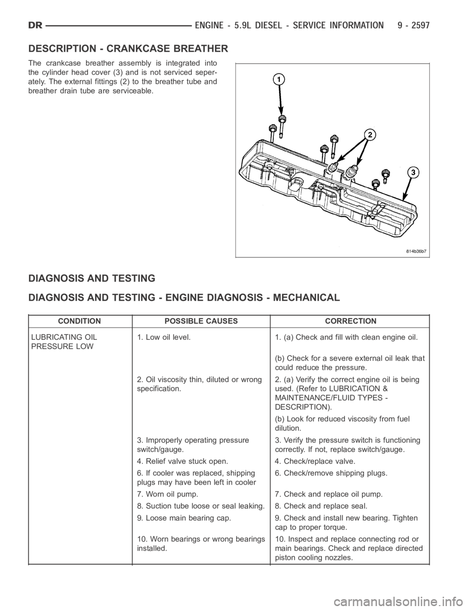
DESCRIPTION - CRANKCASE BREATHER
The crankcase breather assembly is integrated into
the cylinder head cover (3) and is not serviced seper-
ately. The external fittings (2) to the breather tube and
breather drain tube are serviceable.
DIAGNOSIS AND TESTING
DIAGNOSIS AND TESTING - ENGINE DIAGNOSIS - MECHANICAL
CONDITION POSSIBLE CAUSES CORRECTION
LUBRICATING OIL
PRESSURE LOW1. Low oil level. 1. (a) Check and fill with clean engine oil.
(b) Check for a severe external oil leak that
could reduce the pressure.
2. Oil viscosity thin, diluted or wrong
specification.2. (a) Verify the correct engine oil is being
used. (Refer to LUBRICATION &
MAINTENANCE/FLUID TYPES -
DESCRIPTION).
(b) Look for reduced viscosity from fuel
dilution.
3. Improperly operating pressure
switch/gauge.3. Verify the pressure switch is functioning
correctly. If not, replace switch/gauge.
4. Relief valve stuck open. 4. Check/replace valve.
6. If cooler was replaced, shipping
plugs may have been left in cooler6. Check/remove shipping plugs.
7. Worn oil pump. 7. Check and replace oil pump.
8. Suction tube loose or seal leaking. 8. Check and replace seal.
9. Loose main bearing cap. 9. Check and install new bearing. Tighten
cap to proper torque.
10. Worn bearings or wrong bearings
installed.10. Inspect and replace connecting rod or
main bearings. Check and replace directed
piston cooling nozzles.
Page 1911 of 5267
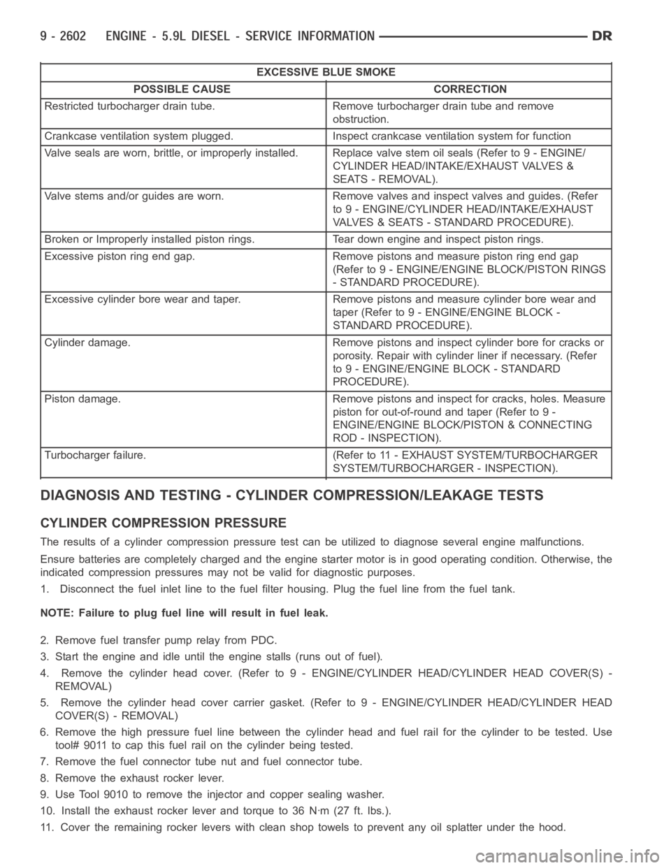
EXCESSIVE BLUE SMOKE
POSSIBLE CAUSE CORRECTION
Restricted turbocharger drain tube. Remove turbocharger drain tube and remove
obstruction.
Crankcase ventilation system plugged. Inspect crankcase ventilation system for function
Valve seals are worn, brittle, or improperly installed. Replace valve stemoilseals(Referto9-ENGINE/
CYLINDER HEAD/INTAKE/EXHAUST VALVES &
SEATS - REMOVAL).
Valve stems and/or guides are worn. Remove valves and inspect valves and guides. (Refer
to 9 - ENGINE/CYLINDER HEAD/INTAKE/EXHAUST
VALVES & SEATS - STANDARD PROCEDURE).
Broken or Improperly installed piston rings. Tear down engine and inspectpiston rings.
Excessive piston ring end gap. Remove pistons and measure piston ring end gap
(Refer to 9 - ENGINE/ENGINE BLOCK/PISTON RINGS
- STANDARD PROCEDURE).
Excessive cylinder bore wear and taper. Remove pistons and measure cylinder bore wear and
taper (Refer to 9 - ENGINE/ENGINE BLOCK -
STANDARD PROCEDURE).
Cylinder damage. Remove pistons and inspect cylinder bore for cracks or
porosity. Repair with cylinder liner if necessary. (Refer
to 9 - ENGINE/ENGINE BLOCK - STANDARD
PROCEDURE).
Piston damage. Remove pistons and inspect for cracks, holes. Measure
piston for out-of-round and taper (Refer to 9 -
ENGINE/ENGINE BLOCK/PISTON & CONNECTING
ROD - INSPECTION).
Turbocharger failure. (Refer to 11 - EXHAUST SYSTEM/TURBOCHARGER
SYSTEM/TURBOCHARGER - INSPECTION).
DIAGNOSIS AND TESTING - CYLINDER COMPRESSION/LEAKAGE TESTS
CYLINDER COMPRESSION PRESSURE
The results of a cylinder compressionpressure test can be utilized to diagnose several engine malfunctions.
Ensure batteries are completely charged and the engine starter motor is ingood operating condition. Otherwise, the
indicated compression pressures may not be valid for diagnostic purposes.
1. Disconnect the fuel inlet line to the fuel filter housing. Plug the fuel line from the fuel tank.
NOTE: Failure to plug fuel line will result in fuel leak.
2. Remove fuel transfer pump relay from PDC.
3. Start the engine and idle until the engine stalls (runs out of fuel).
4. Remove the cylinder head cover. (Refer to 9 - ENGINE/CYLINDER HEAD/CYLINDER HEAD COVER(S) -
REMOVAL)
5. Remove the cylinder head cover carrier gasket. (Refer to 9 - ENGINE/CYLINDER HEAD/CYLINDER HEAD
COVER(S) - REMOVAL)
6. Remove the high pressure fuel line between the cylinder head and fuel rail for the cylinder to be tested. Use
tool# 9011 to cap this fuel rail on the cylinder being tested.
7. Remove the fuel connector tube nut and fuel connector tube.
8. Remove the exhaust rocker lever.
9. Use Tool 9010 to remove the injector and copper sealing washer.
10. Install the exhaust rocker lever and torque to 36 Nꞏm (27 ft. lbs.).
11. Cover the remaining rocker levers with clean shop towels to prevent anyoil splatter under the hood.
Page 1912 of 5267
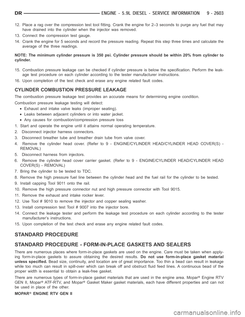
12. Place a rag over the compression test tool fitting. Crank the engine for2–3 seconds to purge any fuel that may
have drained into the cylinder when the injector was removed.
13. Connect the compression test gauge.
14. Crank the engine for 5 seconds and record the pressure reading. Repeat this step three times and calculate the
average of the three readings.
NOTE: The minimum cylinder pressure is 350 psi. Cylinder pressure should be within 20% from cylinder to
cylinder.
15. Combustion pressure leakage can be checked if cylinder pressure is below the specification. Perform the leak-
age test procedure on each cylinder according to the tester manufacturer instructions.
16. Upon completion of the test check and erase any engine related fault codes.
CYLINDER COMBUSTION PRESSURE LEAKAGE
The combustion pressure leakage test provides an accurate means for determining engine condition.
Combustion pressure leakage testing will detect:
Exhaust and intake valve leaks (improper seating).
Leaks between adjacent cylinders or into water jacket.
Any causes for combustion/compression pressure loss
1. Start and operate the engine until it attains normal operating temperature.
2. Disconnect injector harness connectors.
3. Disconnect breather tube and breather drain tube from valve cover.
4. Remove the cylinder head cover. (Refer to 9 - ENGINE/CYLINDER HEAD/CYLINDER HEAD COVER(S) -
REMOVAL)
5. Disconnect harness from injectors.
6. Remove the cylinder head cover carrier gasket. (Refer to 9 - ENGINE/CYLINDER HEAD/CYLINDER HEAD
COVER(S) - REMOVAL)
7. BringthecylindertobetestedtoTDC.
8. Remove the high pressure fuel line between the cylinder head and the fuelrail for the cylinder to be tested.
9. Install capping Tool 9011 onto the rail.
10. Remove the high pressure connector nut and high pressure connector with Tool 9015.
11. Remove the exhaust and intake rocker lever.
12. Use Tool # 9010 to remove the injector and copper sealing washer.
13. Install compression test Tool # 9007 into the injector bore.
14. Connect the leakage tester and perform the leakage test procedure on each cylinder according to the tester
manufacturer’s instructions.
15. Upon completion of the test check and erase any engine related fault codes.
STANDARD PROCEDURE
STANDARD PROCEDURE - FORM-IN-PLACE GASKETS AND SEALERS
There are numerous places where form-in-place gaskets are used on the engine. Care must be taken when apply-
ing form-in-place gaskets to assure obtaining the desired results.Do not use form-in-place gasket material
unless specified.Bead size, continuity, and location are of great importance. Too thin a bead can result in leakage
while too much can result in spill-overwhich can break off and obstruct fluid feed lines. A continuous bead of the
proper width is essential to obtain a leak-free gasket.
There are numerous types of form-in-place gasket materials that are used in the engine area. Mopar
Engine RTV
GEN II, Mopar
ATF-RTV, and MoparGasket Maker gasket materials, each have different properties and can not
be used in place of the other.
MOPAR
ENGINE RTV GEN II
Page 1918 of 5267
NOTE: Extreme care should be used to keep dirt/debris from entering the fuel lines. Plastic caps should be
used on the ends of the fuel lines.
46. Loosen # 6 fuel line shield bolts and rotate shield out of the way.
47. Remove cylinder # 5 and # 6 high pressure fuel lines.
48. Remove the rear engine lift bracket.
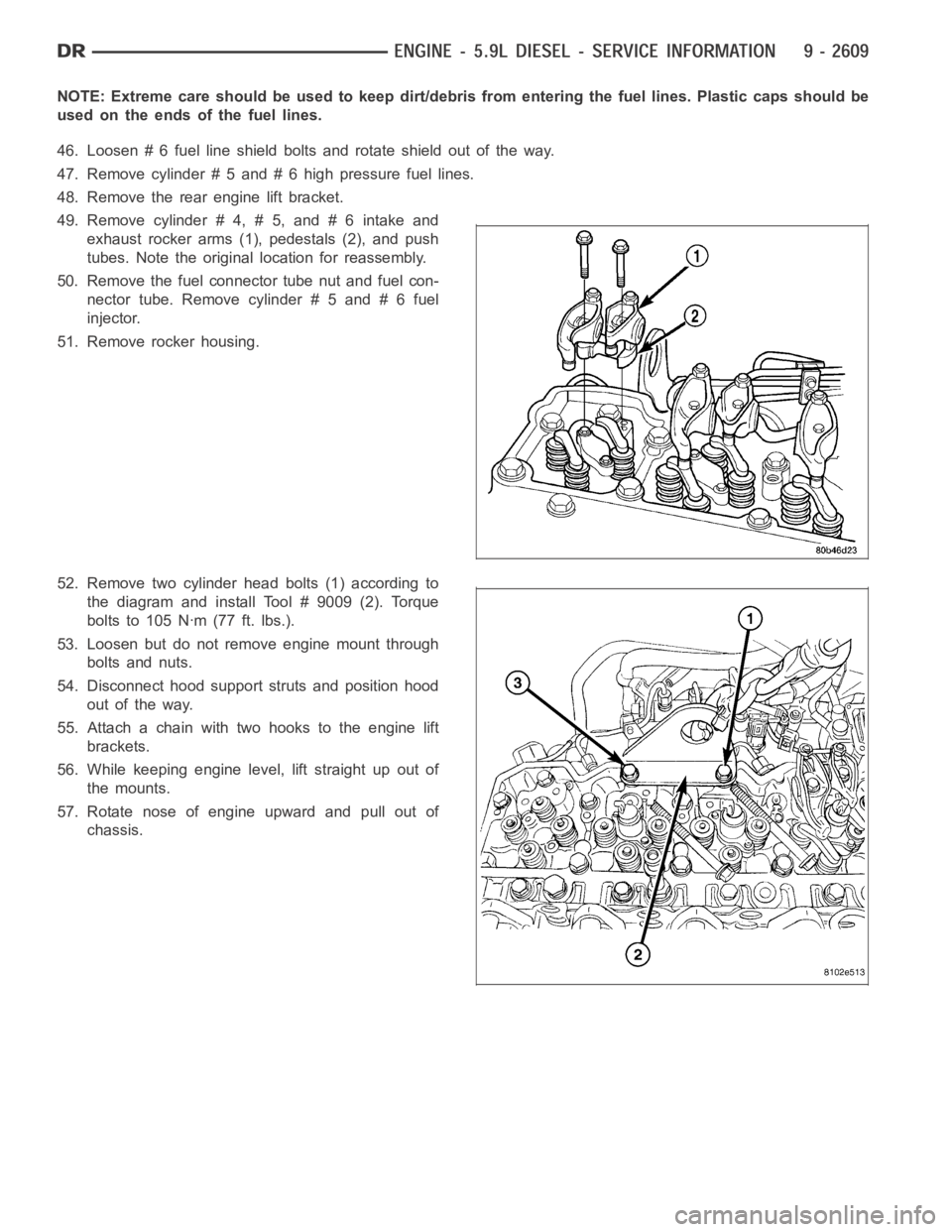
49. Remove cylinder # 4, # 5, and # 6 intake and
exhaust rocker arms (1), pedestals (2), and push
tubes. Note the original location for reassembly.
50. Remove the fuel connector tube nut and fuel con-
nector tube. Remove cylinder # 5 and # 6 fuel
injector.
51. Remove rocker housing.
52. Remove two cylinder head bolts (1) according to
the diagram and install Tool # 9009 (2). Torque
bolts to 105 Nꞏm (77 ft. lbs.).
53. Loosen but do not remove engine mount through
bolts and nuts.
54. Disconnect hood support struts and position hood
out of the way.
55. Attach a chain with two hooks to the engine lift
brackets.
56. While keeping engine level, lift straight up out of
the mounts.
57. Rotate nose of engine upward and pull out of
chassis.
Page 1919 of 5267
INSTALLATION - ENGINE
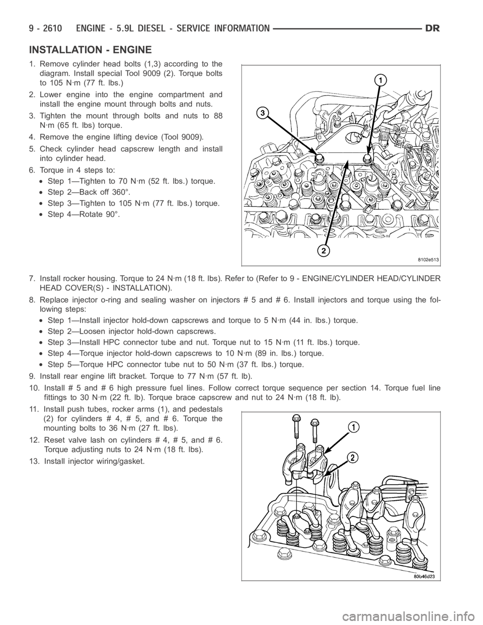
1. Remove cylinder head bolts (1,3) according to the
diagram. Install special Tool 9009 (2). Torque bolts
to 105 Nꞏm (77 ft. lbs.)
2. Lower engine into the engine compartment and
install the engine mount through bolts and nuts.
3. Tighten the mount through bolts and nuts to 88
Nꞏm (65 ft. lbs) torque.
4. Remove the engine lifting device (Tool 9009).
5. Check cylinder head capscrew length and install
into cylinder head.
6. Torque in 4 steps to:
Step 1—Tighten to 70 Nꞏm (52 ft. lbs.) torque.
Step 2—Back off 360°.
Step 3—Tighten to 105 Nꞏm (77 ft. lbs.) torque.
Step 4—Rotate 90°.
7. Install rocker housing. Torque to 24 Nꞏm (18 ft. lbs). Refer to (Refer to 9- ENGINE/CYLINDER HEAD/CYLINDER
HEAD COVER(S) - INSTALLATION).
8. Replace injector o-ring and sealing washer on injectors # 5 and # 6. Install injectors and torque using the fol-
lowing steps:
Step 1—Install injector hold-down capscrews and torque to 5 Nꞏm (44 in. lbs.) torque.
Step 2—Loosen injector hold-down capscrews.
Step 3—Install HPC connector tube and nut. Torque nut to 15 Nꞏm (11 ft. lbs.)torque.
Step 4—Torque injector hold-down capscrews to 10 Nꞏm (89 in. lbs.) torque.
Step 5—Torque HPC connector tube nut to 50 Nꞏm (37 ft. lbs.) torque.
9. Install rear engine lift bracket. Torque to 77 Nꞏm (57 ft. lb).
10. Install # 5 and # 6 high pressure fuel lines. Follow correct torque sequence per section 14. Torque fuel line
fittings to 30 Nꞏm (22 ft. lb). Torque brace capscrew and nut to 24 Nꞏm (18 ft.lb).
11. Install push tubes, rocker arms (1), and pedestals
(2) for cylinders # 4, # 5, and # 6. Torque the
mounting bolts to 36 Nꞏm (27 ft. lbs).
12. Reset valve lash on cylinders # 4, # 5, and # 6.
Torque adjusting nuts to 24 Nꞏm (18 ft. lbs).
13. Install injector wiring/gasket.
Page 1927 of 5267
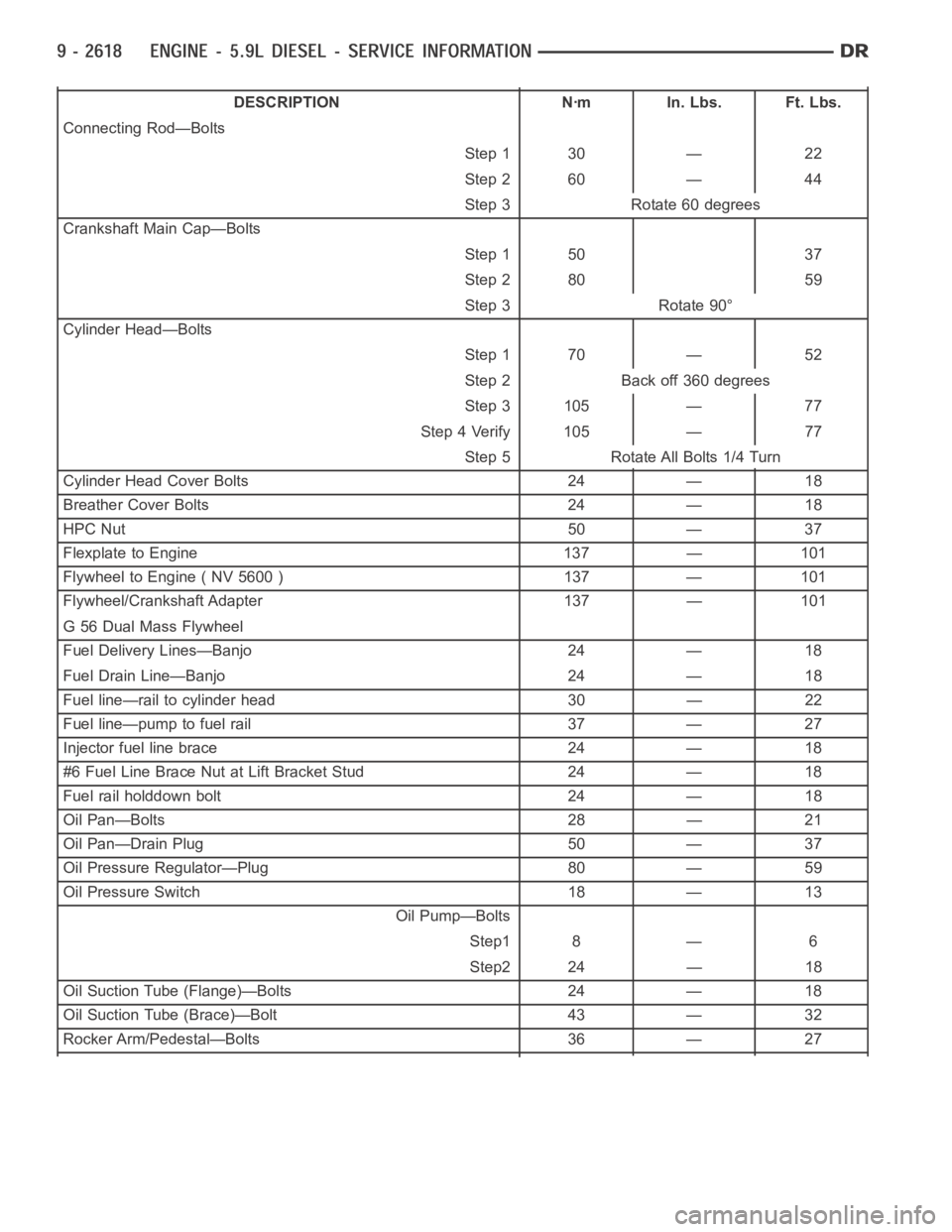
DESCRIPTION Nꞏm In. Lbs. Ft. Lbs.
Connecting Rod—Bolts
Step 1 30 — 22
Step 2 60 — 44
Step 3 Rotate 60 degrees
Crankshaft Main Cap—Bolts
Step 1 50 37
Step 2 80 59
Step 3 Rotate 90°
Cylinder Head—Bolts
Step 1 70 — 52
Step 2 Back off 360 degrees
Step 3 105 — 77
Step 4 Verify 105 — 77
Step 5 Rotate All Bolts 1/4 Turn
Cylinder Head Cover Bolts 24 — 18
Breather Cover Bolts 24 — 18
HPC Nut 50 — 37
Flexplate to Engine 137 — 101
Flywheel to Engine ( NV 5600 ) 137 — 101
Flywheel/Crankshaft Adapter 137 — 101
G 56 Dual Mass Flywheel
Fuel Delivery Lines—Banjo 24 — 18
Fuel Drain Line—Banjo 24 — 18
Fuel line—rail to cylinder head 30 — 22
Fuel line—pump to fuel rail 37 — 27
Injector fuel line brace 24 — 18
#6 Fuel Line Brace Nut at Lift Bracket Stud 24 — 18
Fuel rail holddown bolt 24 — 18
Oil Pan—Bolts 28 — 21
Oil Pan—Drain Plug 50 — 37
Oil Pressure Regulator—Plug 80 — 59
Oil Pressure Switch 18 — 13
Oil Pump—Bolts
Step1 8 — 6
Step2 24 — 18
Oil Suction Tube (Flange)—Bolts 24 — 18
Oil Suction Tube (Brace)—Bolt 43 — 32
Rocker Arm/Pedestal—Bolts 36 — 27