2006 DODGE RAM SRT-10 fuel cap
[x] Cancel search: fuel capPage 2386 of 5267
OPERATION
High-pressure fuel is supplied from the injection pump, through a high-pressure fuel line, into a fuel rail, through
high-pressure lines, through steel connectors and into the solenoid actuated fuel injector. The ECM actuates the
solenoid causing the needle valve to rise and fuel flows through the spray holes in the nozzle tip into the combus-
tion chamber.
Each fuel injector is connected to the fuel rail by a high-pressure fuel line and a steel connector. This steel con-
nector is positioned into the cylinder head and sealed with an O-ring. The connector is retained in the cylinder head
by a nut (fitting) that is threaded into the cylinder head.
The torquing force of this threaded nut (fitting) provides a sealing pressure between the fuel line connector and the
fuel injector.Retaining nut torque is very critical.If the nut (fitting) is under torqued, the mating surfaces will not
seal and a high-pressure fuel leak will result. If the fitting is over torqued, the connector and injector will deform and
also cause a high-pressure fuel leak. This leak will be inside the cylinderhead and will not be visible. The result will
be a possible fuel injector miss-fire and low power, or a no-start condition.
The fuel injectors use hole type nozzles. High-pressure flows into the side of the injector, the ECM activates the
solenoid causing the injector needle to lift and fuel to be injected. The clearances in the nozzle bore are extremely
small and any dirt or contaminants will cause the injector to stick. Because of this, it is very important to do a
thorough cleaning of any lines before opening up any fuel system component. Always cover or cap any open fuel
connections before a fuel system repair is performed.
Each fuel injector connector tube contains an edge filter that is designedto break up small contaminants before
entering the fuel injector.The edge filters are not a substitute for proper cleaning and covering of allfuel
system components during repair.
The bottom of each fuel injector is sealed to the cylinder head with a1.5mmthick copper shim (gasket). The correct
thickness shim must always be re-installed after removing an injector.
Fuel pressure in the injector circuit decreases after injection. The injector needle valve is immediately closed and
fuel flow into the combustion chamber is stopped. Exhaust gases are prevented from entering the injector nozzle by
the needle valve.
REMOVAL
CAUTION: Refer to Cleaning Fuel System Parts.
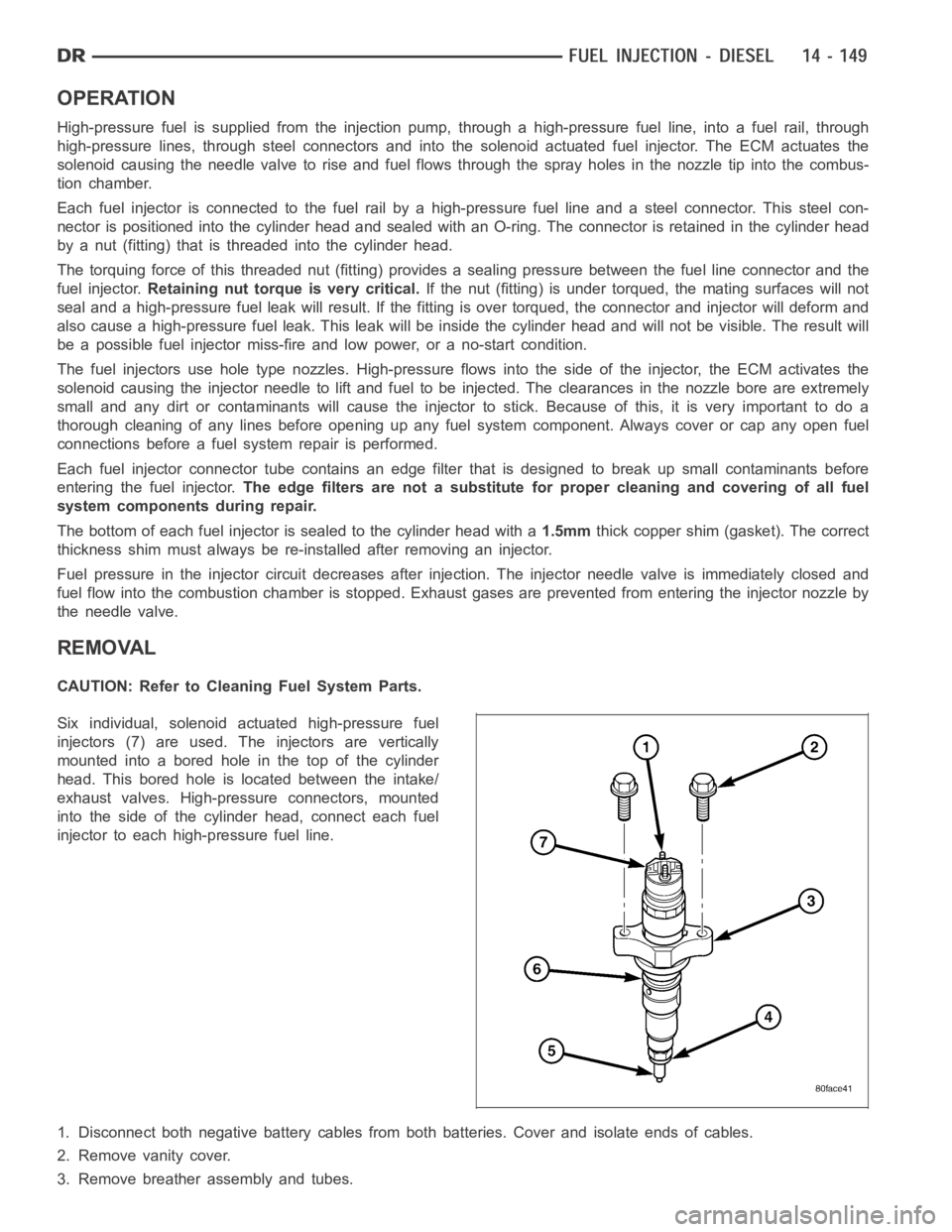
Six individual, solenoid actuated high-pressure fuel
injectors (7) are used. The injectors are vertically
mounted into a bored hole in the top of the cylinder
head. This bored hole is located between the intake/
exhaust valves. High-pressure connectors, mounted
into the side of the cylinder head, connect each fuel
injector to each high-pressure fuel line.
1. Disconnect both negative battery cables from both batteries. Cover andisolate ends of cables.
2. Remove vanity cover.
3. Remove breather assembly and tubes.
Page 2392 of 5267
FUEL INJECTOR RAIL
DESCRIPTION
The fuel injector rail is bolted to the top of the intake manifold.
OPERATION
The fuel rail is used as a distribution device to supply high-pressure fuelto the high-pressure fuel lines.
REMOVAL
CAUTION: Cleanliness cannot be overemphasized when handling or replacingdieselfuelsystemcompo-
nents. This especially includes the fuel injectors, high-pressure fuel lines and fuel injection pump. Very tight
tolerances are used with these parts. Dirt contamination could cause rapid part wear and possible plugging
of fuel injector nozzle tip holes. This in turn could lead to possible engine misfire. Always wash/clean any
fuel system component thoroughly before disassembly and then air dry. Capor cover any open part after
disassembly. Before assembly, examine each part for dirt, grease or othercontaminants and clean if nec-
essary. When installing new parts, lubricate them with clean engine oil orclean diesel fuel only.
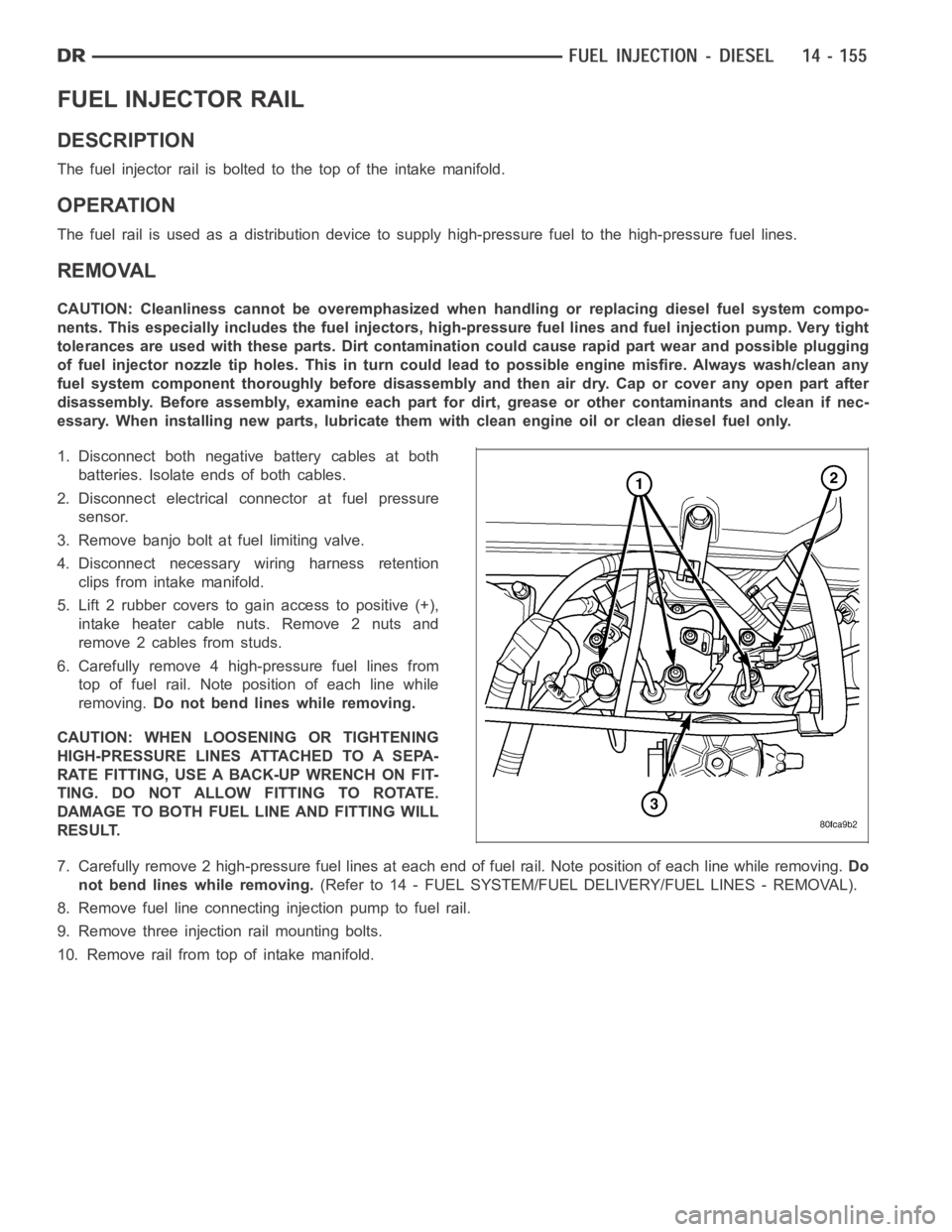
1. Disconnect both negative battery cables at both
batteries. Isolate ends of both cables.
2. Disconnect electrical connector at fuel pressure
sensor.
3. Remove banjo bolt at fuel limiting valve.
4. Disconnect necessary wiring harness retention
clips from intake manifold.
5. Lift 2 rubber covers to gain access to positive (+),
intake heater cable nuts. Remove 2 nuts and
remove 2 cables from studs.
6. Carefully remove 4 high-pressure fuel lines from
top of fuel rail. Note position of each line while
removing.Do not bend lines while removing.
CAUTION: WHEN LOOSENING OR TIGHTENING
HIGH-PRESSURE LINES ATTACHED TO A SEPA-
RATE FITTING, USE A BACK-UP WRENCH ON FIT-
TING. DO NOT ALLOW FITTING TO ROTATE.
DAMAGE TO BOTH FUEL LINE AND FITTING WILL
RESULT.
7. Carefully remove 2 high-pressure fuel lines at each end of fuel rail. Note position of each line while removing.Do
not bend lines while removing.(Refer to 14 - FUEL SYSTEM/FUEL DELIVERY/FUEL LINES - REMOVAL).
8. Remove fuel line connectinginjection pump to fuel rail.
9. Remove three injection rail mounting bolts.
10. Remove rail from top of intake manifold.
Page 2711 of 5267
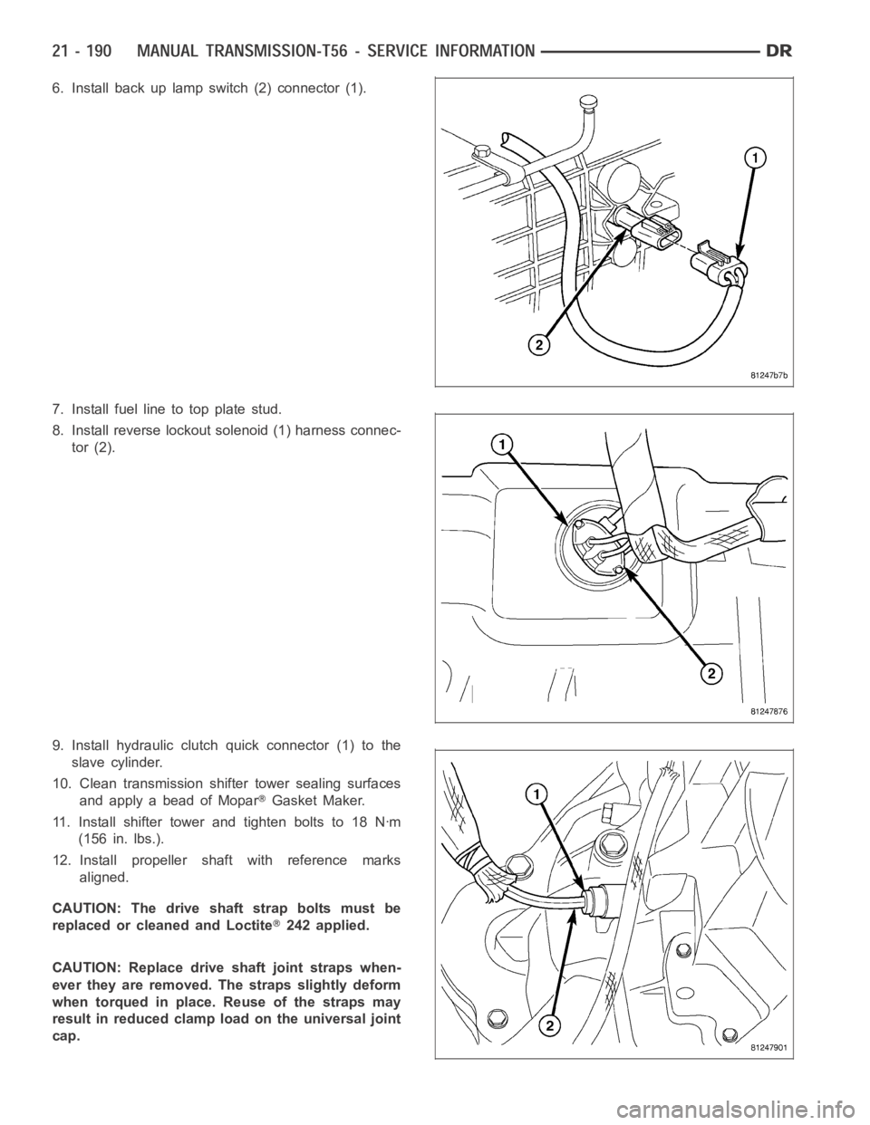
6. Install back up lamp switch (2) connector (1).
7. Install fuel line to top plate stud.
8. Install reverse lockout solenoid (1) harness connec-
tor (2).
9. Install hydraulic clutch quick connector (1) to the
slave cylinder.
10. Clean transmission shifter tower sealing surfaces
and apply a bead of Mopar
Gasket Maker.
11. Install shifter tower and tighten bolts to 18 Nꞏm
(156 in. lbs.).
12. Install propeller shaft with reference marks
aligned.
CAUTION: The drive shaft strap bolts must be
replaced or cleaned and Loctite
242 applied.
CAUTION: Replace drive shaft joint straps when-
ever they are removed. The straps slightly deform
when torqued in place. Reuse of the straps may
result in reduced clamp load on the universal joint
cap.
Page 4323 of 5267
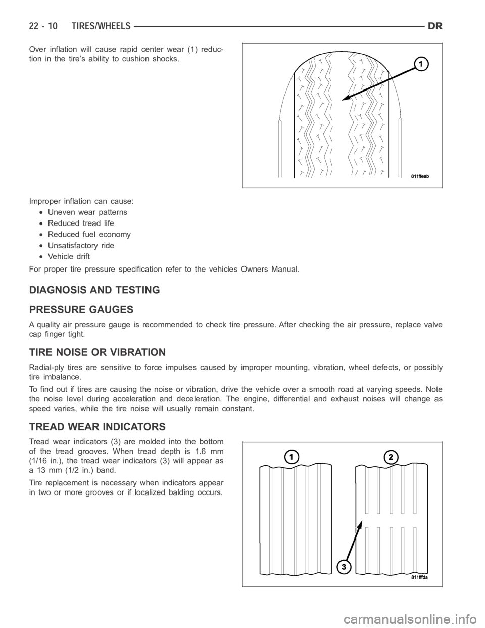
Over inflation will cause rapid center wear (1) reduc-
tion in the tire’s ability to cushion shocks.
Improper inflation can cause:
Uneven wear patterns
Reduced tread life
Reduced fuel economy
Unsatisfactory ride
Vehicle drift
For proper tire pressure specification refer to the vehicles Owners Manual.
DIAGNOSIS AND TESTING
PRESSURE GAUGES
A quality air pressure gauge is recommended to check tire pressure. After checking the air pressure, replace valve
cap finger tight.
TIRE NOISE OR VIBRATION
Radial-ply tires are sensitive to force impulses caused by improper mounting, vibration, wheel defects, or possibly
tire imbalance.
To find out if tires are causing the noise or vibration, drive the vehicle over a smooth road at varying speeds. Note
the noise level during acceleration and deceleration. The engine, differential and exhaust noises will change as
speed varies, while the tire noise will usually remain constant.
TREAD WEAR INDICATORS
Tread wear indicators (3) are molded into the bottom
of the tread grooves. When tread depth is 1.6 mm
(1/16 in.), the tread wear indicators (3) will appear as
a 13 mm (1/2 in.) band.
Tire replacement is necessary when indicators appear
in two or more grooves or if localized balding occurs.
Page 5196 of 5267
CATALYST MONITOR
To comply with clean air regulations, vehicles are equipped with catalytic converters. These converters reduce the
emission of hydrocarbons, oxides of nitrogen and carbon monoxide.
Normal vehicle miles or engine misfire can cause a catalyst to decay. This can increase vehicle emissions and
deteriorate engine performance, driveability and fuel economy.
The catalyst monitor uses dual oxygen sensors (O2S’s) to monitor the efficiency of the converter. The dual O2S’s
sensor strategy is based on the fact that as a catalyst deteriorates, its oxygen storage capacity and its efficiency are
both reduced. By monitoring the oxygen storage capacity of a catalyst, itsefficiency can be indirectly calculated. The
upstream O2S is used to detect the amount of oxygen in the exhaust gas beforethe gas enters the catalytic con-
verter. The PCM calculates the A/F mixture from the output of the O2S. A low voltage indicates high oxygen content
(lean mixture). A high voltage indicates a low content of oxygen (rich mixture).
When the upstream O2S detects a lean condition, there is an abundance of oxygen in the exhaust gas. A function-
ing converter would store this oxygen so it can use it for the oxidation of HCand CO. As the converter absorbs the
oxygen, there will be a lack of oxygen downstream of the converter. The output of the downstream O2S will indicate
limited activity in this condition.
As the converter loses the ability to store oxygen, the condition can be detected from the behavior of the down-
stream O2S. When the efficiency drops, no chemical reaction takes place. This means the concentration of oxygen
will be the same downstream as upstream. The output voltage of the downstream O2S copies the voltage of the
upstream sensor. The only difference is a time lag (seen by the PCM) betweenthe switching of the O2S’s.
To monitor the system, the number of lean-to-rich switches of upstream anddownstream O2S’s is counted. The
ratio of downstream switches to upstream switches is used to determine whether the catalyst is operating properly.
An effective catalyst will have fewer downstream switches than it has upstream switches i.e., a ratio closer to zero.
For a totally ineffective catalyst, this ratio will be one-to-one, indicating that no oxidation occurs in the device.
The system must be monitored so that when catalyst efficiency deteriorates and exhaust emissions increase to over
the legal limit, the MIL will be illuminated.
TRIP DEFINITION
The term “Trip” has different meanings depending on what the circumstances are. If the MIL (Malfunction Indicator
Lamp) is OFF, a Trip is defined as when the Oxygen Sensor Monitor and the Catalyst Monitor have been completed
in the same drive cycle.
When any Emission DTC is set, the MIL on the dash is turned ON. When the MIL is ON, it takes 3 good trips to turn
the MIL OFF. In this case, it depends on what type of DTC is set to know what a “Trip” is.
For the Fuel Monitor or Mis-Fire Monitor (continuous monitor), the vehicle must be operated in the “Similar Condition
Window” for a specified amount of time to be considered a Good Trip.
If a Non-Continuous OBDII Monitor fails twice in a row and turns ON the MIL, re-running that monitor which previ-
ously failed, on the next start-up and passing the monitor, is considered tobeaGoodTrip.Thesewillincludethe
following:
Oxygen Sensor
Catalyst Monitor
Purge Flow Monitor
Leak Detection Pump Monitor (if equipped)
EGR Monitor (if equipped)
Oxygen Sensor Heater Monitor
If any other Emission DTC is set (not an OBDII Monitor), a Good Trip is considered to be when the Oxygen Sensor
Monitor and Catalyst Monitor have been completed; or 2 Minutes of engine run time if the Oxygen Sensor Monitor
or Catalyst Monitor have been stopped from running.
It can take up to 2 Failures in a row to turn on the MIL. After the MIL is ON, it takes3GoodTripstoturntheMIL
OFF. After the MIL is OFF, the PCM will self-erase the DTC after 40 Warm-up cycles. A Warm-up cycle is counted
when the ECT (Engine Coolant Temperature Sensor) has crossed 160°F (71.1C) and has risen by at least 40°F
(4.4°C) since the engine has been started.
Page 5203 of 5267
page page
EVAPORATIVE EMISSIONS
DESCRIPTION - EVAP SYSTEM ................ 13
SPECIFICATIONS
TORQUE ................................... 13
SOLENOID-EVAP/PURGE
DESCRIPTION ................................ 14
OPERATION .................................. 14
REMOVAL .................................... 14
INSTALLATION ............................... 14
CAP - FUEL FILLER
DESCRIPTION ................................ 15
OPERATION .................................. 15
REMOVAL
REMOVAL/INSTALLATION ................... 15
PUMP-LEAK DETECTION
DESCRIPTION ................................ 16
OPERATION .................................. 16
REMOVAL .................................... 19
INSTALLATION ............................... 20
ORVR
DESCRIPTION ................................ 21OPERATION .................................. 21
PUMP-NATURAL VAC LEAK DETECTION
DESCRIPTION ................................ 22
OPERATION .................................. 22
REMOVAL .................................... 23
INSTALLATION ............................... 26
VA LV E - P C V
DESCRIPTION ................................ 30
OPERATION .................................. 32
DIAGNOSIS AND TESTING
PCV VALVE - 3.7L V-6/ 4.7L V-8 .............. 33
REMOVAL .................................... 35
INSTALLATION ............................... 36
LINES - VACUUM
DESCRIPTION ................................ 37
CANISTER - VAPOR
DESCRIPTION ................................ 38
OPERATION .................................. 40
REMOVAL .................................... 40
INSTALLATION ............................... 46
Page 5206 of 5267
CAP - FUEL FILLER
DESCRIPTION
The plastic fuel tank filler tube cap isthreaded onto the end of the fuel fill tube. Certain models are equipped with
a 1/4 turn cap.
OPERATION
The loss of any fuel or vapor out of fuel filler tube is prevented by the use ofa pressure-vacuum fuel fill cap. Relief
valves inside the cap will release fuel tank pressure at predetermined pressures. Fuel tank vacuum will also be
released at predetermined values. This cap must be replaced by a similar unit if replacement is necessary. This is
in order for the system to remain effective.
CAUTION: Remove fill cap before servicing any fuel system component to relieve tank pressure. If equipped
with a Leak Detection Pump (LDP), or NVLD system, the cap must be tightened securely. If cap is left loose,
a Diagnostic Trouble Code (DTC) may be set.
REMOVAL
REMOVAL/INSTALLATION
If replacement of the 1/4 turn fuel tank filler tube cap is necessary, it mustbereplacedwithanidenticalcaptobe
sure of correct system operation.
CAUTION: Remove the fuel tank filler tube cap to relieve fuel tank pressure. The cap must be removed prior
to disconnecting any fuel system component or before draining the fuel tank.
Page 5207 of 5267
PUMP-LEAK DETECTION
DESCRIPTION
Vehicles equipped with JTEC engine control modules use a leak detection pump. Vehicles equipped with NGC
engine control modules use an NVLD pump. Refer to Natural Vacuum - Leak Detection (NVLD) for additional infor-
mation.
The evaporative emission system is designed to prevent the escape of fuel vapors from the fuel system. Leaks in
the system, even small ones, can allow fuel vapors to escape into the atmosphere. Government regulations require
onboard testing to make sure that the evaporative (EVAP) system is functioning properly. The leak detection system
tests for EVAP system leaks and blockage. It also performs self-diagnostics. During self-diagnostics, the Powertrain
Control Module (PCM) first checks the Leak Detection Pump (LDP) for electrical and mechanical faults. If the first
checks pass, the PCM then uses the LDP to seal the vent valve and pump air intothe system to pressurize it. If a
leak is present, the PCM will continue pumping the LDP to replace the air that leaks out. The PCM determines the
size of the leak based on how fast/long it must pump the LDP as it tries to maintain pressure in the system.
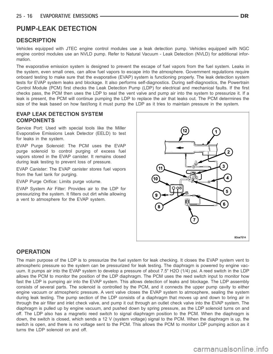
EVAP LEAK DETECTION SYSTEM
COMPONENTS
Service Port: Used with special tools like the Miller
Evaporative Emissions Leak Detector (EELD) to test
for leaks in the system.
EVAP Purge Solenoid: The PCM uses the EVAP
purge solenoid to control purging of excess fuel
vapors stored in the EVAP canister. It remains closed
during leak testing to prevent loss of pressure.
EVAP Canister: The EVAP canister stores fuel vapors
from the fuel tank for purging.
EVAP Purge Orifice: Limits purge volume.
EVAP System Air Filter: Provides air to the LDP for
pressurizing the system. It filters out dirt while allowing
a vent to atmosphere for the EVAP system.
OPERATION
The main purpose of the LDP is to pressurize the fuel system for leak checking. It closes the EVAP system vent to
atmospheric pressure so the system can be pressurized for leak testing. The diaphragm is powered by engine vac-
uum. It pumps air into the EVAP system to develop a pressure of about 7.5
H2O (1/4) psi. A reed switch in the LDP
allows the PCM to monitor the position of the LDP diaphragm. The PCM uses thereed switch input to monitor how
fast the LDP is pumping air into the EVAP system. This allows detection of leaks and blockage. The LDP assembly
consists of several parts. The solenoid is controlled by the PCM, and it connects the upper pump cavity to either
engine vacuum or atmospheric pressure. A vent valve closes the EVAP systemto atmosphere, sealing the system
during leak testing. The pump section of the LDP consists of a diaphragm that moves up and down to bring air in
through the air filter and inlet check valve, and pump it out through an outlet check valve into the EVAP system. The
diaphragm is pulled up by engine vacuum, and pushed down by spring pressure, as the LDP solenoid turns on and
off. The LDP also has a magnetic reed switch to signal diaphragm position tothe PCM. When the diaphragm is
down, the switch is closed, which sends a 12 V (system voltage) signal to thePCM. When the diaphragm is up, the
switch is open, and there is no voltage sent to the PCM. This allows the PCM tomonitor LDP pumping action as it
turns the LDP solenoid on and off.