Page 704 of 5267
7.ECM
Reconnect the ECM harness connectors.
Turn the ignition on.
While monitoring scan tool, use a jumper wire to connect the (K916)
return circuit with the (C918) signal circuit at the sensor harness con-
nector.
Did DTC P0532 set?
Ye s>>
Refer to the INTERMITTENT CONDITION Symptom (Diag-
nostic Procedure). (Refer to 9 - ENGINE - DIAGNOSIS
AND TESTING)
No>>
Replace the ECM.
Perform POWERTRAIN VERIFICATION TEST VER - 1
(DIESEL). (Refer to 8 - ELECTRICAL/ELECTRONIC CON-
TROL MODULES/ENGINE CONTROL MODULE - DIAG-
NOSIS AND TESTING)
Page 706 of 5267

When Monitored:
When the ignition is on.
Set Condition:
When the signal from the #1 intake air heater output does not match the signal from the #1 intake air heater
feedback.
Possible Causes
LOOSE CONNECTION
INTAKEAIRHEATERRELAY
SIGNAL CIRCUIT OPEN FROM RELAY TO ECM
SIGNAL CIRCUIT SHORTED TO BATTERY NEGATIVE
ECM
INTERMITTENT CONDITION
Always perform the Pre-Diagnostic Troubleshooting procedure before proceeding. (Refer to 9 - ENGINE -
DIAGNOSIS AND TESTING)
Diagnostic Test
1.RELAY CLICKING
Ignition on, engine not running.
With the scan tool, actuate the #1 Intake Air Heater.
Can you hear the Relay clicking?
Ye s>>
Go To 2
No>>
Go To 3
2.LOOSE CONNECTION
While the relay is clicking , wiggle the wiring harness and connectors.
Does this interrupt the clicking?
Ye s>>
Repair the poor connection.
Perform POWERTRAIN VERIFICATION TEST VER - 1 (DIESEL). (Refer to 8 - ELECTRICAL/ELEC-
TRONIC CONTROL MODULES/ENGINE CONTROL MODULE - DIAGNOSIS AND TESTING)
No>>
Go To 3
3.INTAKE AIR HEATER RELAY
Turn the ignition off.
Remove the Intake Air Heater #1 Relay.
Check connectors - Clean/repair as necessary.
Measure the resistance between the signal and return posts of the intake air heater relay.
Is the resistance between 15 and 25 Ohms?
Ye s>>
Go To 4
No>>
Replace the Intake Air Heater #1 relay.
Perform POWERTRAIN VERIFICATION TEST VER - 1 (DIESEL). (Refer to 8 - ELECTRICAL/ELEC-
TRONIC CONTROL MODULES/ENGINE CONTROL MODULE - DIAGNOSIS AND TESTING)
Page 707 of 5267

4.SIGNAL CIRCUIT OPEN FROM RELAY TO ECM
Disconnect the ECM harness connectors.
Check connectors - Clean/repair as necessary.
Measure the resistance of the intake air heater relay signal circuit between the ECM connector and the intake air
heater relay connector.
Is the resistance less than 10 Ohms?
Ye s>>
Go To 5
No>>
Repair the open signal circuit from PDC to ECM harness connector.
Perform POWERTRAIN VERIFICATION TEST VER - 1 (DIESEL). (Refer to 8 - ELECTRICAL/ELEC-
TRONIC CONTROL MODULES/ENGINE CONTROL MODULE - DIAGNOSIS AND TESTING)
5.SIGNAL CIRCUIT SHORTED TO BATTERY NEGATIVE
Measure the voltage between the signal circuit of the intake air heater relay and battery negative.
Is the voltage greater than 1 volts?
Ye s>>
Repair the signal circuit shorted to Battery negative.
Perform POWERTRAIN VERIFICATION TEST VER - 1 (DIESEL). (Refer to 8 - ELECTRICAL/ELEC-
TRONIC CONTROL MODULES/ENGINE CONTROL MODULE - DIAGNOSIS AND TESTING)
No>>
Go To 6
6.ECM
Reconnect the ECM harness connectors.
Disconnect the intake air heater relay signal wire and use a jumper to connect it to battery negative.
Turn the ignition on.
With the scan tool, read DTCs.
Did DTC P0542 set?
Ye s>>
Refer to the INTERMITTENT CONDITION Symptom (Diagnostic Procedure). (Refer to 9 - ENGINE -
DIAGNOSIS AND TESTING)
No>>
Replace the ECM.
Perform POWERTRAIN VERIFICATION TEST VER - 1 (DIESEL). (Refer to 8 - ELECTRICAL/ELEC-
TRONIC CONTROL MODULES/ENGINE CONTROL MODULE - DIAGNOSIS AND TESTING)
Page 709 of 5267

When Monitored:
When the ignition is on.
Set Condition:
When the signal from the #1 Intake Air Heater output does not match the signal from the #1 Intake Air Heater
feedback.
Possible Causes
LOOSE CONNECTION
INTAKEAIRHEATERRELAY
SIGNAL CIRCUIT SHORTED TO BATTERY NEGATIVE
ECM
INTERMITTENT CONDITION
Always perform the Pre-Diagnostic Troubleshooting procedure before proceeding. (Refer to 9 - ENGINE -
DIAGNOSIS AND TESTING)
Diagnostic Test
1.RELAY CLICKING
Ignition on, engine not running.
With the scan tool, actuate the Intake Air Heater relay.
Can you hear the Relay clicking?
Ye s>>
Go To 2
No>>
Go To 3
2.LOOSE CONNECTION
While the relay is clicking , wiggle the wiring harness and connectors.
Does this interrupt the clicking?
Ye s>>
Repair the poor connection.
Perform POWERTRAIN VERIFICATION TEST VER - 1 (DIESEL). (Refer to 8 - ELECTRICAL/ELEC-
TRONIC CONTROL MODULES/ENGINE CONTROL MODULE - DIAGNOSIS AND TESTING)
No>>
Go To 3
3.INTAKE AIR HEATER RELAY
Turn the ignition off.
Remove the Intake Air Heater Relay.
NOTE: Check connectors - Clean/repair as necessary.
Measure the resistance between the signal and return posts of the intake air heater relay.
Is the resistance between 15 and 25 Ohms?
Ye s>>
Go To 4
No>>
Replace the Intake Air Heater relay.
Perform POWERTRAIN VERIFICATION TEST VER - 1 (DIESEL). (Refer to 8 - ELECTRICAL/ELEC-
TRONIC CONTROL MODULES/ENGINE CONTROL MODULE - DIAGNOSIS AND TESTING)
Page 710 of 5267

4.SIGNAL CIRCUIT SHORTED TO BATTERY NEGATIVE
Disconnect the ECM harness connector(s).
NOTE: Check connectors - Clean/repair as necessary.
Measure the resistance between the signal circuit of the intake air heaterrelay and battery negative.
Is the resistance greater than 100 K ohms?
Ye s>>
Go To 5
No>>
Repair signal circuit shorted to battery negative.
Perform POWERTRAIN VERIFICATION TEST VER - 1 (DIESEL). (Refer to 8 - ELECTRICAL/ELEC-
TRONIC CONTROL MODULES/ENGINE CONTROL MODULE - DIAGNOSIS AND TESTING)
5.SIGNAL CIRCUIT SHORTED TO OTHER CIRCUITS
Measure the resistance between the signal circuit of the intake air heaterrelay and all other circuits in the ECM
harness connector.
Is the resistance greater than 100 K ohms?
Ye s>>
Go To 6
No>>
Repair signal circuit shorted to other circuits.
Perform POWERTRAIN VERIFICATION TEST VER - 1 (DIESEL). (Refer to 8 - ELECTRICAL/ELEC-
TRONIC CONTROL MODULES/ENGINE CONTROL MODULE - DIAGNOSIS AND TESTING)
6.ECM
Reconnect the ECM harness connectors.
Turn the ignition on.
Disconnect the intake air heater relay signal wire.
Did DTC P0542 or 2608 set?
Ye s>>
Refer to the INTERMITTENT CONDITION Symptom (Diagnostic Procedure). (Refer to 9 - ENGINE -
DIAGNOSIS AND TESTING)
No>>
Replace the ECM.
Perform POWERTRAIN VERIFICATION TEST VER - 1 (DIESEL). (Refer to 8 - ELECTRICAL/ELEC-
TRONIC CONTROL MODULES/ENGINE CONTROL MODULE - DIAGNOSIS AND TESTING)
Page 713 of 5267

4.BATTERY TERMINAL CONNECTIONS
Visually inspect the positive and negative connections at the batteries and inspect the battery negative connections
at the engine block.
Are the connections free of corrosion and are they tight?
Ye s>>
Go To 5
No>>
Repair the poor connections.
Perform POWERTRAIN VERIFICATION TEST VER - 1 (DIESEL). (Refer to 8 - ELECTRICAL/ELEC-
TRONIC CONTROL MODULES/ENGINE CONTROL MODULE - DIAGNOSIS AND TESTING)
5.ACCESSORY WIRING
Check for add-on or accessory wiring at positive (+) terminal of the battery
Are there any damaged wires at the battery?
Ye s>>
Repair accessory wiring.
Perform POWERTRAIN VERIFICATION TEST VER - 1 (DIESEL). (Refer to 8 - ELECTRICAL/ELEC-
TRONIC CONTROL MODULES/ENGINE CONTROL MODULE - DIAGNOSIS AND TESTING)
No>>
Go To 6
6.BATTERY(S)
Perform battery load test using the Midtronics Micro 420 battery system tester.
Did the battery(s) pass the test?
Ye s>>
Go To 7
No>>
Replace the weak battery or batteries.
Perform POWERTRAIN VERIFICATION TEST VER - 1 (DIESEL). (Refer to 8 - ELECTRICAL/ELEC-
TRONIC CONTROL MODULES/ENGINE CONTROL MODULE - DIAGNOSIS AND TESTING)
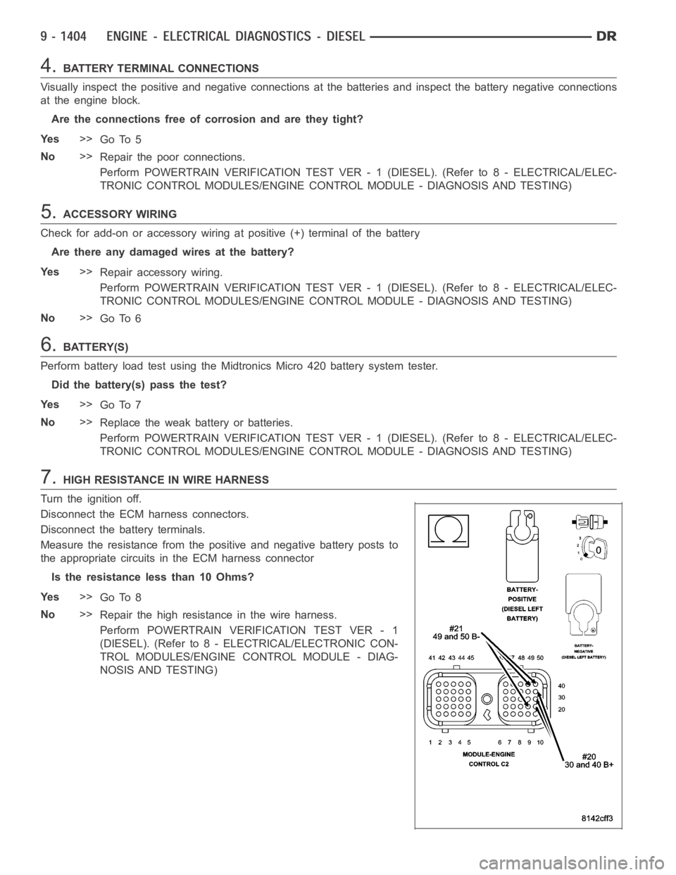
7.HIGH RESISTANCE IN WIRE HARNESS
Turn the ignition off.
Disconnect the ECM harness connectors.
Disconnect the battery terminals.
Measure the resistance from the positive and negative battery posts to
the appropriate circuits in the ECM harness connector
Is the resistance less than 10 Ohms?
Ye s>>
Go To 8
No>>
Repair the high resistance in the wire harness.
Perform POWERTRAIN VERIFICATION TEST VER - 1
(DIESEL). (Refer to 8 - ELECTRICAL/ELECTRONIC CON-
TROL MODULES/ENGINE CONTROL MODULE - DIAG-
NOSIS AND TESTING)
Page 719 of 5267

When Monitored:
While the ignition is on
Set Condition:
The brake switch status is = to OFF and the not brake switch status is = to ON for a calibrated amount of
time..
Possible Causes
DAMAGED WIRING HARNESS OR CONNECTORS
BRAKE SWITCH CIRCUIT SHORTED TO GROUND (BRAKE SWITCH WILL ALWAYS BE OFF)
BRAKE SWITCH
ECM
Always perform the Pre-Diagnostic Troubleshooting procedure before proceeding. (Refer to 9 - ENGINE -
DIAGNOSIS AND TESTING)
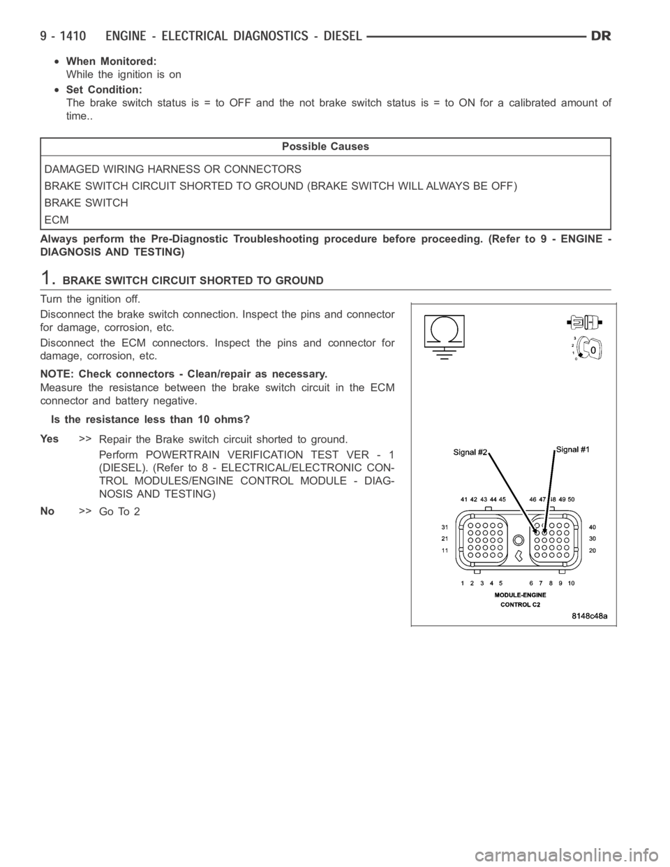
1.BRAKE SWITCH CIRCUIT SHORTED TO GROUND
Turn the ignition off.
Disconnect the brake switch connection. Inspect the pins and connector
for damage, corrosion, etc.
Disconnect the ECM connectors. Inspect the pins and connector for
damage, corrosion, etc.
NOTE: Check connectors - Clean/repair as necessary.
Measure the resistance between the brake switch circuit in the ECM
connector and battery negative.
Is the resistance less than 10 ohms?
Ye s>>
Repair the Brake switch circuit shorted to ground.
Perform POWERTRAIN VERIFICATION TEST VER - 1
(DIESEL). (Refer to 8 - ELECTRICAL/ELECTRONIC CON-
TROL MODULES/ENGINE CONTROL MODULE - DIAG-
NOSIS AND TESTING)
No>>
Go To 2
Page 721 of 5267
4.
Reconnect the brake switch connector.
Using the scan tool, clear the DTC’s.
Turn the ignition on.
Cycle the brake pedal several times.
Using the scan tool, read the DTC’s.
Has the brake switch low DTC returned?
Ye s>>
Replace the brake switch.
Perform POWERTRAIN VERIFICATION TEST VER - 1 (DIESEL). (Refer to 8 - ELECTRICAL/ELEC-
TRONIC CONTROL MODULES/ENGINE CONTROL MODULE - DIAGNOSIS AND TESTING)
No>>
Perform Intermittent condition test. (Refer to 9 - ENGINE - DIAGNOSIS AND TESTING)