2006 DODGE RAM SRT-10 air condition
[x] Cancel search: air conditionPage 1427 of 5267
When Monitored:
Immediately after a cold start, with battery/ambient temperature between 40 Deg. F and 90 Deg. F and coolant
temperature within 10 Deg. F of battery/ambient.
Set Condition:
The state of the switch does not change when the solenoid is energized.
Possible Causes
GOOD TRIP EQUAL TO ZERO
LDP VACUUM SUPPLY
LEAK DETECTION PUMP
(K107) LDP SWITCH SENSE CIRCUIT OPEN
(K107) LDP SWITCH SENSE CIRCUIT SHORTED TO GROUND
PCM
Always perform the Pre-Diagnostic Troubleshooting procedure before proceeding. (Refer to 9 - ENGINE -
DIAGNOSIS AND TESTING)
Diagnostic Test
1.VEHICLE HISTORY AND SERVICE BULLETIN INVESTIGATION
Ignition on, engine not running.
With a scan tool, read DTCs and record the related Freeze Frame data if any DTC(s) are present.
Whether or not any DTC(s) are present you will want to check the following items which may assist in repairing the
customer’s complaint successfully.
Check the vehicles repair history.
If the vehicle has a repair history that pertains to the customer’s currentcomplaint, review the repair.
Inspect the vehicle for any aftermarket accessories that may have been installed incorrectly.
Check for any service bulletin(s) related to the customer’s complaint or DTC(s).
If a service bulletin applies, follow the instructions per the service bulletin.
Choose the following scenario that best applies.
The service bulletin repaired the customer’s complaint.
Testing complete.
A DTC is present, no service bulletins apply, or the service bulletin didn’t repair the customer’s complaint.
Go To 2
2.GOOD TRIP EQUAL TO ZERO
Check for any related TSBs.
Ignition on, engine not running.
With the scan tool, read DTCs and record the related Freeze Frame data.
Is the Good Trip Counter displayed and equal to zero?
Ye s>>
Go To 3
No>>
Refer to the INTERMITTENT CONDITION Diagnostic Procedure.
Perform POWERTRAIN VERIFICATION TEST. (Refer to 9 - ENGINE - STANDARD PROCEDURE)
Page 1431 of 5267
When Monitored:
Continuously when the ignition is on and battery voltage is greater than 10.4 volts.
Set Condition:
The state of the solenoid circuit does not match the PCM’s desired state.
Possible Causes
(K125) GENERATOR SOURCE CIRCUIT OPEN
(K107) LDP SWITCH SIGNAL CIRCUIT OPEN
(K107) LDP SWITCH SIGNAL CIRCUIT SHORTED TO GROUND
(K106) LEAK DETECTION PUMP SOLENOID CONTROL CIRCUIT OPEN
(K106) LDP SOLENOID CONTROL CIRCUIT SHORTED TO GROUND
LEAK DETECTION PUMP
PCM
Always perform the Pre-Diagnostic Troubleshooting procedure before proceeding. (Refer to 9 - ENGINE -
DIAGNOSIS AND TESTING)
Diagnostic Test
1.VEHICLE HISTORY AND SERVICE BULLETIN INVESTIGATION
Ignition on, engine not running.
With a scan tool, read DTCs and record the related Freeze Frame data if any DTC(s) are present.
Whether or not any DTC(s) are present you will want to check the following items which may assist in repairing the
customer’s complaint successfully.
Check the vehicles repair history.
If the vehicle has a repair history that pertains to the customer’s currentcomplaint, review the repair.
Inspect the vehicle for any aftermarket accessories that may have been installed incorrectly.
Check for any service bulletin(s) related to the customer’s complaint or DTC(s).
If a service bulletin applies, follow the instructions per the service bulletin.
Choose the following scenario that best applies.
The service bulletin repaired the customer’s complaint.
Testing complete.
A DTC is present, no service bulletins apply, or the service bulletin didn’t repair the customer’s complaint.
Go To 2
2.GOOD TRIP EQUAL TO ZERO
Ignition on, engine not running.
With the scan tool, read DTCs.
Is the Good Trip Counter displayed and equal to zero?
Ye s>>
Go To 3
No>>
Refer to the INTERMITTENT CONDITION Diagnostic Procedure.
Perform POWERTRAIN VERIFICATION TEST. (Refer to 9 - ENGINE - STANDARD PROCEDURE)
Page 1436 of 5267
When Monitored:
Ignition on and engine running.
Set Condition:
An open or shorted condition in the Hydraulic Fan Solenoid control circuitis detected by the Powertrain Control
Module.
Possible Causes
RADIATOR FAN INOP
(K342) FUSED ASD RELAY OUTPUT CIRCUIT
(C240) COOLING FAN CONTROL CIRCUIT OPEN
(C240) COOLING FAN CONTROL CIRCUIT SHORTED TO GROUND
HYDRAULIC FAN
PCM
Always perform the Pre-Diagnostic Troubleshooting procedure before proceeding. (Refer to 9 - ENGINE -
DIAGNOSIS AND TESTING)
1.RADIATOR FAN INOP
Ignition on, engine not running.
With the scan tool, perform the Hydraulic Fan Solenoid Test found under Engine Test and Systems Test.
Does the Radiator Fan operate properly?
Ye s>>
Refer to the INTERMITTENT CONDITIONSymptom (Diagnostic Procedure).
Perform POWERTRAIN VERIFICATION TEST. (Refer to 9 - ENGINE - STANDARD PROCEDURE)
No>>
Go To 2
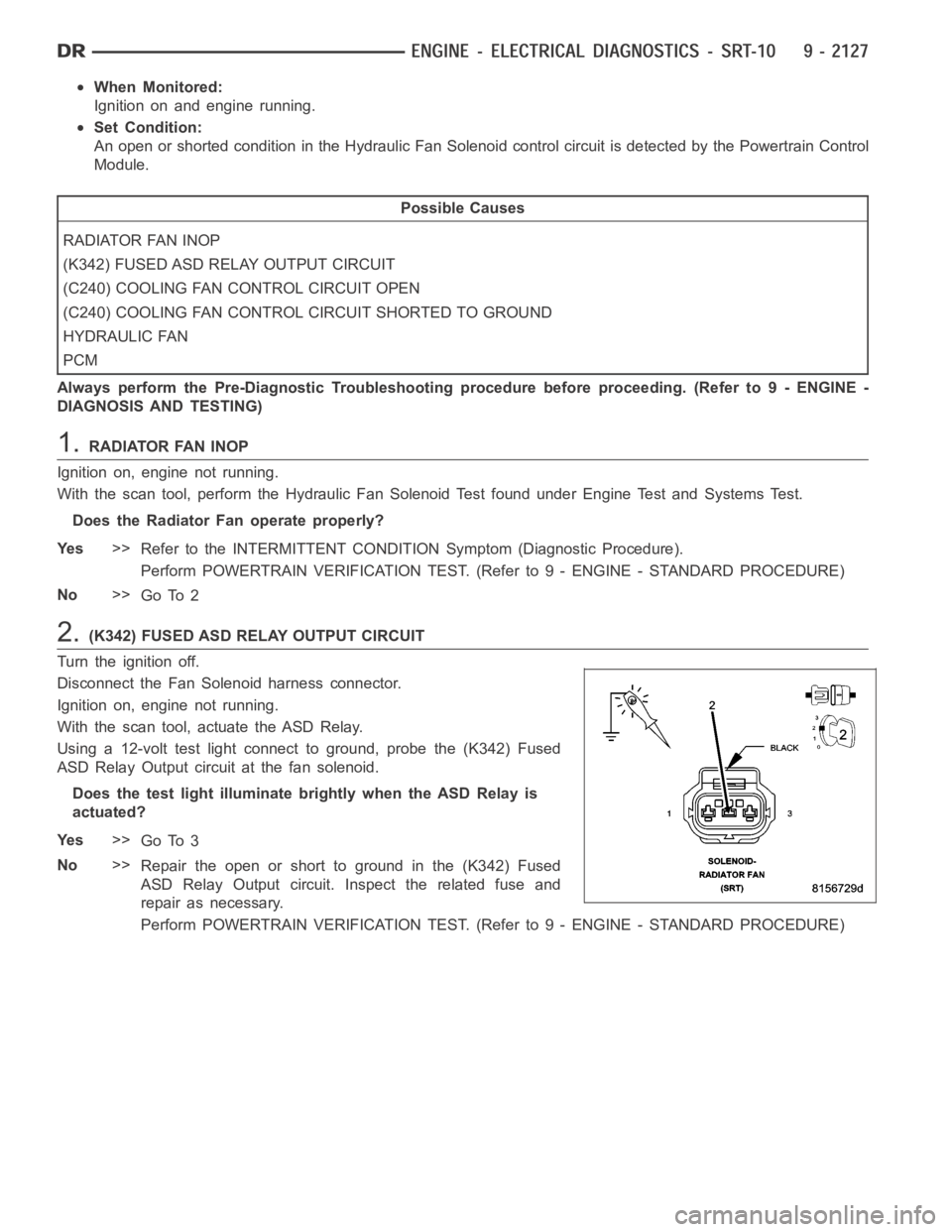
2.(K342) FUSED ASD RELAY OUTPUT CIRCUIT
Turn the ignition off.
Disconnect the Fan Solenoid harness connector.
Ignition on, engine not running.
With the scan tool, actuate the ASD Relay.
Using a 12-volt test light connect to ground, probe the (K342) Fused
ASD Relay Output circuit at the fan solenoid.
Does the test light illuminate brightly when the ASD Relay is
actuated?
Ye s>>
Go To 3
No>>
Repair the open or short to ground in the (K342) Fused
ASD Relay Output circuit. Inspect the related fuse and
repair as necessary.
Perform POWERTRAIN VERIFICATION TEST. (Refer to 9 - ENGINE - STANDARD PROCEDURE)
Page 1440 of 5267
When Monitored:
With the ignition key on and the engine speed greater than 0 RPM.
Set Condition:
When the PCM regulates the generator field and there are no detected field problems, but the voltage output
does not decrease.
Possible Causes
(K20) GENERATOR FIELD CONTROL CIRCUIT SHORTED TO GROUND
GENERATOR FIELD COIL SHORTED TO GROUND
BATTERY TEMPERATURE SENSOR
PCM
Always perform the Pre-Diagnostic Troubleshooting procedure before proceeding. (Refer to 9 - ENGINE -
DIAGNOSIS AND TESTING)
Diagnostic Test
1.CHARGING SYSTEM OPERATION
NOTE: Battery must be fully charged and be capable of passing a load test.
NOTE: Generator Belt tension and condition must be checked before continuing.
Ignition on, engine not running.
With the scan tool, read DTCs and the related Freeze Frame data then clear theDTCs.
With scan tool, actuate the Generator Field Driver.
With a 12-volt test light connected to ground, backprobe the (K20) Gen Field Control circuit in the back of Generator
Field harness connector.
Does the test light illuminate brightly and flash?
Ye s>>
Go To 2
No>>
Refer to the INTERMITTENT CONDITION Diagnostic Procedure.
Perform the POWERTRAIN VERIFICATION TEST. (Refer to 9 - ENGINE - STANDARD PROCEDURE)
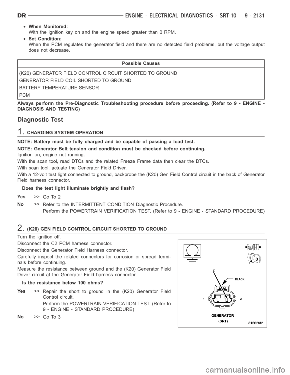
2.(K20) GEN FIELD CONTROL CIRCUIT SHORTED TO GROUND
Turn the ignition off.
Disconnect the C2 PCM harness connector.
Disconnect the Generator Field Harness connector.
Carefully inspect the related connectors for corrosion or spread termi-
nals before continuing.
Measure the resistance between ground and the (K20) Generator Field
Driver circuit at the Generator Field harness connector.
Istheresistancebelow100ohms?
Ye s>>
Repair the short to ground in the (K20) Generator Field
Control circuit.
Perform the POWERTRAIN VERIFICATION TEST. (Refer to
9 - ENGINE - STANDARD PROCEDURE)
No>>
Go To 3
Page 1473 of 5267
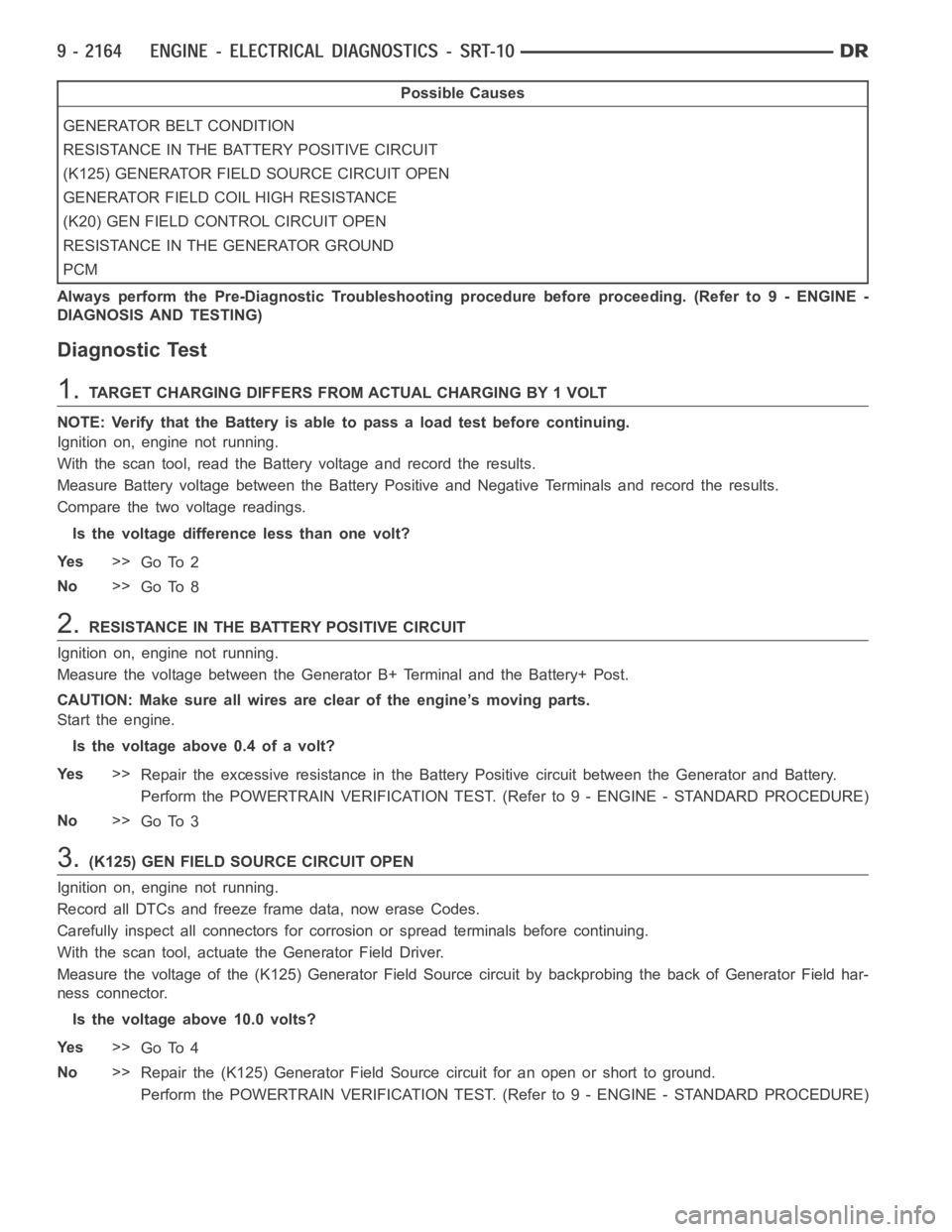
Possible Causes
GENERATOR BELT CONDITION
RESISTANCE IN THE BATTERY POSITIVE CIRCUIT
(K125) GENERATOR FIELD SOURCE CIRCUIT OPEN
GENERATOR FIELD COIL HIGH RESISTANCE
(K20) GEN FIELD CONTROL CIRCUIT OPEN
RESISTANCE IN THE GENERATOR GROUND
PCM
Always perform the Pre-Diagnostic Troubleshooting procedure before proceeding. (Refer to 9 - ENGINE -
DIAGNOSIS AND TESTING)
Diagnostic Test
1.TARGET CHARGING DIFFERS FROM ACTUAL CHARGING BY 1 VOLT
NOTE: Verify that the Battery is able to pass a load test before continuing.
Ignition on, engine not running.
With the scan tool, read the Battery voltage and record the results.
Measure Battery voltage between the Battery Positive and Negative Terminals and record the results.
Compare the two voltage readings.
Is the voltage difference less than one volt?
Ye s>>
Go To 2
No>>
Go To 8
2.RESISTANCE IN THE BATTERY POSITIVE CIRCUIT
Ignition on, engine not running.
Measure the voltage between the Generator B+ Terminal and the Battery+ Post.
CAUTION: Make sure all wires are clear of the engine’s moving parts.
Start the engine.
Is the voltage above 0.4 of a volt?
Ye s>>
Repair the excessive resistance in the Battery Positive circuit between the Generator and Battery.
Perform the POWERTRAIN VERIFICATION TEST. (Refer to 9 - ENGINE - STANDARD PROCEDURE)
No>>
Go To 3
3.(K125) GEN FIELD SOURCE CIRCUIT OPEN
Ignition on, engine not running.
Record all DTCs and freeze frame data, now erase Codes.
Carefully inspect all connectors for corrosion or spread terminals before continuing.
With the scan tool, actuate the Generator Field Driver.
Measure the voltage of the (K125) Generator Field Source circuit by backprobing the back of Generator Field har-
ness connector.
Is the voltage above 10.0 volts?
Ye s>>
Go To 4
No>>
Repair the (K125) Generator Field Source circuit for an open or short to ground.
Perform the POWERTRAIN VERIFICATION TEST. (Refer to 9 - ENGINE - STANDARD PROCEDURE)
Page 1475 of 5267
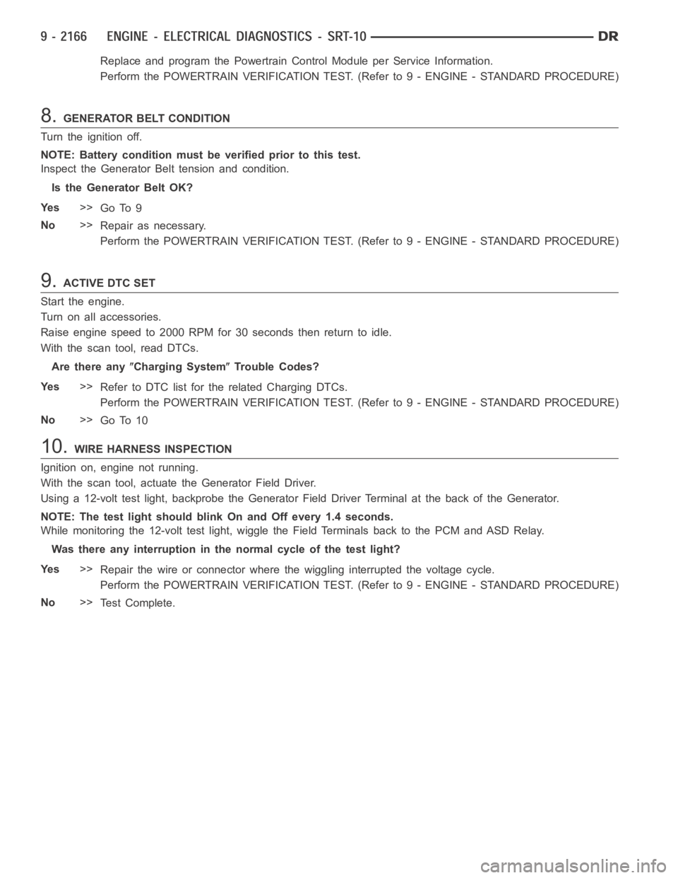
Replace and program the Powertrain Control Module per Service Information.
Perform the POWERTRAIN VERIFICATION TEST. (Refer to 9 - ENGINE - STANDARD PROCEDURE)
8.GENERATOR BELT CONDITION
Turn the ignition off.
NOTE: Battery condition must be verified prior to this test.
Inspect the Generator Belt tension and condition.
Is the Generator Belt OK?
Ye s>>
Go To 9
No>>
Repair as necessary.
Perform the POWERTRAIN VERIFICATION TEST. (Refer to 9 - ENGINE - STANDARD PROCEDURE)
9.ACTIVE DTC SET
Start the engine.
Turn on all accessories.
Raise engine speed to 2000 RPM for 30 seconds then return to idle.
With the scan tool, read DTCs.
Are there any
Charging SystemTrouble Codes?
Ye s>>
Refer to DTC list for the related Charging DTCs.
Perform the POWERTRAIN VERIFICATION TEST. (Refer to 9 - ENGINE - STANDARD PROCEDURE)
No>>
Go To 10
10.WIRE HARNESS INSPECTION
Ignition on, engine not running.
With the scan tool, actuate the Generator Field Driver.
Using a 12-volt test light, backprobe the Generator Field Driver Terminalat the back of the Generator.
NOTE: The test light should blink On and Off every 1.4 seconds.
While monitoring the 12-volt test light, wiggle the Field Terminals back to the PCM and ASD Relay.
Was there any interruption in the normal cycle of the test light?
Ye s>>
Repair the wire or connector where the wiggling interrupted the voltage cycle.
Perform the POWERTRAIN VERIFICATION TEST. (Refer to 9 - ENGINE - STANDARD PROCEDURE)
No>>
Te s t C o m p l e t e .
Page 1481 of 5267
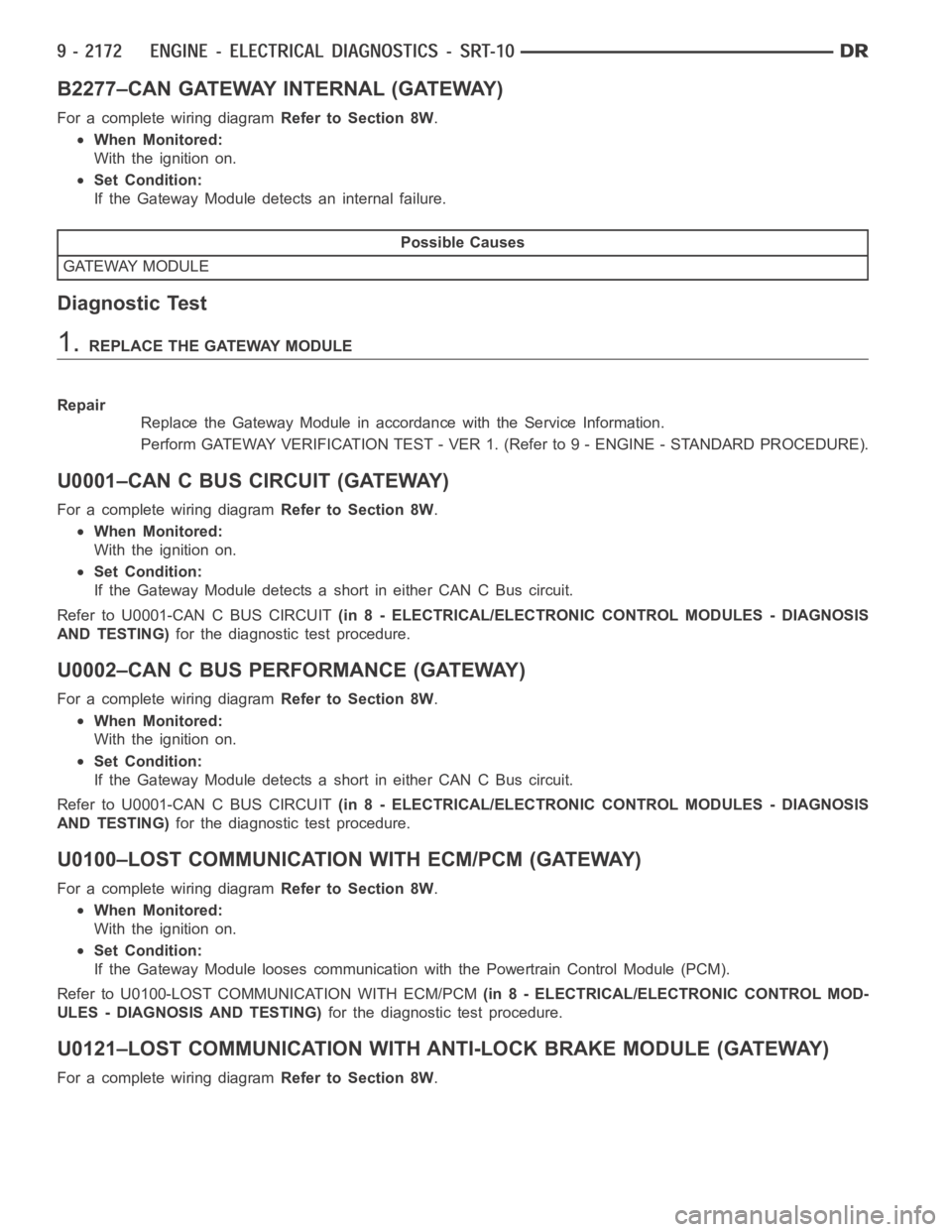
B2277–CAN GATEWAY INTERNAL (GATEWAY)
For a complete wiring diagramRefer to Section 8W.
When Monitored:
With the ignition on.
Set Condition:
If the Gateway Module detects an internal failure.
Possible Causes
GATEWAY MODULE
Diagnostic Test
1.REPLACE THE GATEWAY MODULE
Repair
Replace the Gateway Module in accordance with the Service Information.
Perform GATEWAY VERIFICATION TEST - VER 1. (Refer to 9 - ENGINE - STANDARD PROCEDURE).
U0001–CAN C BUS CIRCUIT (GATEWAY)
For a complete wiring diagramRefer to Section 8W.
When Monitored:
With the ignition on.
Set Condition:
If the Gateway Module detects a short in either CAN C Bus circuit.
Refer to U0001-CAN C BUS CIRCUIT(in 8 - ELECTRICAL/ELECTRONIC CONTROL MODULES - DIAGNOSIS
AND TESTING)for the diagnostic test procedure.
U0002–CAN C BUS PERFORMANCE (GATEWAY)
For a complete wiring diagramRefer to Section 8W.
When Monitored:
With the ignition on.
Set Condition:
If the Gateway Module detects a short in either CAN C Bus circuit.
Refer to U0001-CAN C BUS CIRCUIT(in 8 - ELECTRICAL/ELECTRONIC CONTROL MODULES - DIAGNOSIS
AND TESTING)for the diagnostic test procedure.
U0100–LOST COMMUNICATION WITH ECM/PCM (GATEWAY)
For a complete wiring diagramRefer to Section 8W.
When Monitored:
With the ignition on.
Set Condition:
If the Gateway Module looses communication with the Powertrain Control Module (PCM).
Refer to U0100-LOST COMMUNICATION WITH ECM/PCM(in 8 - ELECTRICAL/ELECTRONIC CONTROL MOD-
ULES - DIAGNOSIS AND TESTING)for the diagnostic test procedure.
U0121–LOST COMMUNICATION WITH ANTI-LOCK BRAKE MODULE (GATEWAY)
For a complete wiring diagramRefer to Section 8W.
Page 1484 of 5267
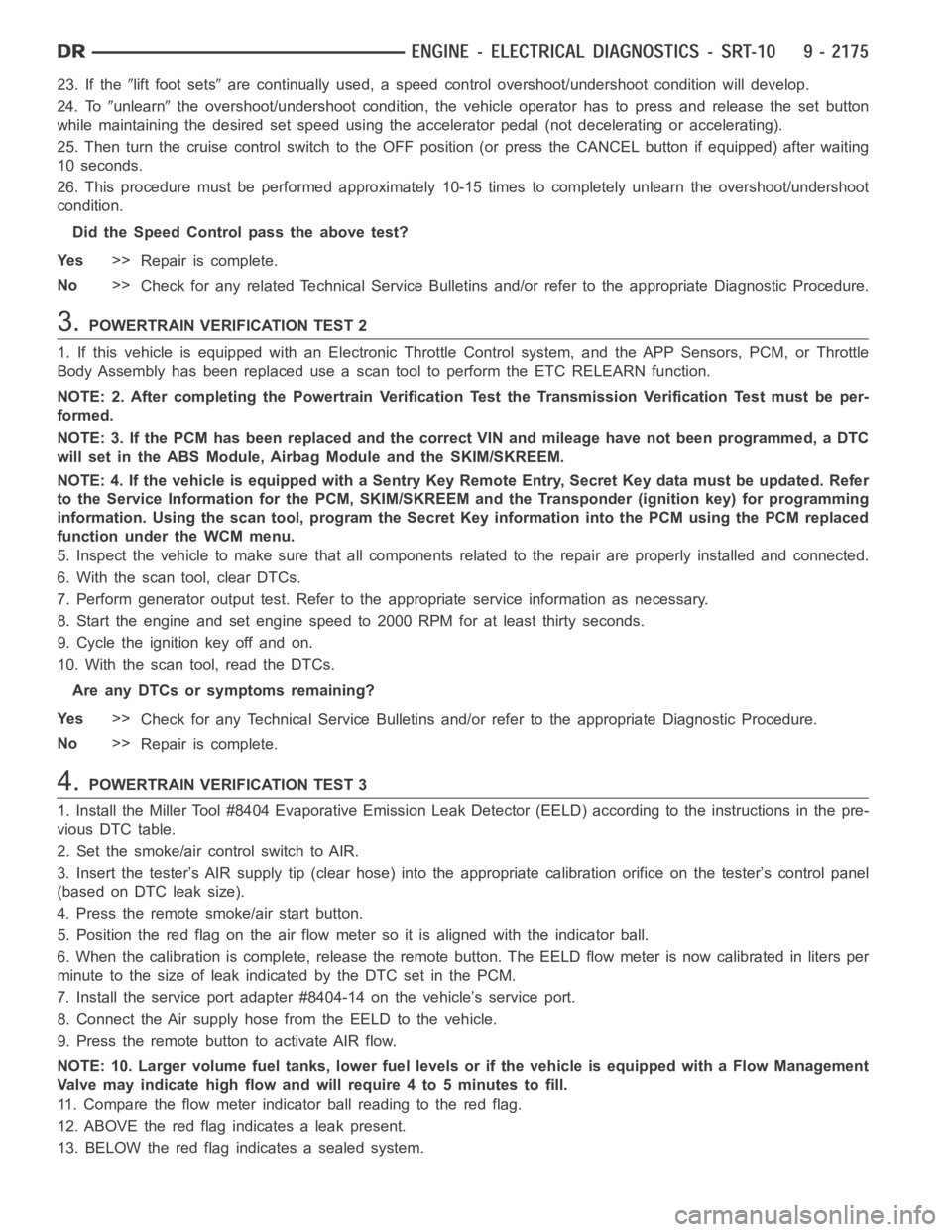
23. If thelift foot setsare continually used, a speed control overshoot/undershoot condition will develop.
24. To
unlearnthe overshoot/undershoot condition, the vehicle operator has to press and release the set button
while maintaining the desired set speedusing the accelerator pedal (not decelerating or accelerating).
25. Then turn the cruise control switch to the OFF position (or press the CANCEL button if equipped) after waiting
10 seconds.
26. This procedure must be performed approximately 10-15 times to completely unlearn the overshoot/undershoot
condition.
Did the Speed Control pass the above test?
Ye s>>
Repair is complete.
No>>
Check for any related Technical Service Bulletins and/or refer to the appropriate Diagnostic Procedure.
3.POWERTRAIN VERIFICATION TEST 2
1. If this vehicle is equipped with an Electronic Throttle Control system,and the APP Sensors, PCM, or Throttle
Body Assembly has been replaced use a scan tool to perform the ETC RELEARN function.
NOTE: 2. After completing the Powertrain Verification Test the Transmission Verification Test must be per-
formed.
NOTE: 3. If the PCM has been replaced and the correct VIN and mileage have notbeen programmed, a DTC
will set in the ABS Module, Airbag Module and the SKIM/SKREEM.
NOTE: 4. If the vehicle is equipped with a Sentry Key Remote Entry, Secret Key data must be updated. Refer
to the Service Information for the PCM, SKIM/SKREEM and the Transponder (ignition key) for programming
information. Using the scan tool, program the Secret Key information intothe PCM using the PCM replaced
function under the WCM menu.
5. Inspect the vehicle to make sure that all components related to the repair are properly installed and connected.
6. With the scan tool, clear DTCs.
7. Perform generator output test. Refer to the appropriate service information as necessary.
8. Start the engine and set engine speed to 2000 RPM for at least thirty seconds.
9. Cycle the ignition key off and on.
10. With the scan tool, read the DTCs.
Are any DTCs or symptoms remaining?
Ye s>>
Check for any Technical Service Bulletins and/or refer to the appropriateDiagnostic Procedure.
No>>
Repair is complete.
4.POWERTRAIN VERIFICATION TEST 3
1. Install the Miller Tool #8404 Evaporative Emission Leak Detector (EELD) according to the instructions in the pre-
vious DTC table.
2. Set the smoke/air control switch to AIR.
3. Insert the tester’s AIR supply tip (clear hose) into the appropriate calibration orifice on the tester’s control panel
(based on DTC leak size).
4. Press the remote smoke/air start button.
5. Position the red flag on the air flow meter so it is aligned with the indicator ball.
6. When the calibration is complete, release the remote button. The EELD flow meter is now calibrated in liters per
minute to the size of leak indicated by the DTC set in the PCM.
7. Install the service port adapter #8404-14 on the vehicle’s service port.
8. Connect the Air supply hose from the EELD to the vehicle.
9. Press the remote button to activate AIR flow.
NOTE: 10. Larger volume fuel tanks, lower fuel levels or if the vehicle is equipped with a Flow Management
Valve may indicate high flow and will require 4 to 5 minutes to fill.
11. Compare the flow meter indicator ball reading to the red flag.
12. ABOVE the red flag indicates a leak present.
13. BELOW the red flag indicates a sealed system.