2006 DODGE RAM SRT-10 air condition
[x] Cancel search: air conditionPage 1268 of 5267
When Monitored:
With engine temperature greater than 170° F, fuel control in closed loop, engine idling for 2 minutes, no low
fuel, MAP less than 15.7 inches mercury and barometric altitude less than 8,000 feet.
Set Condition:
After having passed the Leak Detection Pump (LDP) test, no air flow throughthe evaporative system is
detected by the EVAP monitor.
Possible Causes
EVAP PURGE HOSE (SOLENOID TO CANISTER)
EVAP PURGE HOSE (CANISTER TO FUEL TANK)
EVAP PURGE SOLENOID VACUUM SUPPLY
EVAP PURGE SOLENOID (LEAKS/STUCK OPEN)
EVAP PURGE SOLENOID
For the Engine circuit diagram (Refer to 8 - ELECTRICAL/ELECTRONIC CONTROL MODULES/ENGINE CON-
TROL MODULE - SCHEMATIC - ELECTRICAL)
Diagnostic Test
1.VEHICLE HISTORY AND SERVICE BULLETIN INVESTIGATION
Ignition on, engine not running.
With a scan tool, read DTCs and record the related Freeze Frame data if any DTC(s) are present.
Whether or not any DTC(s) are present you will want to check the following items which may assist in repairing the
customer’s complaint successfully.
Check the vehicles repair history.
If the vehicle has a repair history that pertains to the customer’s currentcomplaint, review the repair.
Inspect the vehicle for any aftermarket accessories that may have been installed incorrectly.
Check for any service bulletin(s) related to the customer’s complaint or DTC(s).
If a service bulletin applies, follow the instructions per the service bulletin.
Choose the following scenario that best applies.
The service bulletin repaired the customer’s complaint.
Testing complete.
A DTC is present, no service bulletins apply, or the service bulletin didn’t repair the customer’s complaint.
Go To 2
2.GOOD TRIP EQUAL TO ZERO
Check for any related TSBs.
Ignition on, engine not running.
With the scan tool, read DTCs and record the related Freeze Frame data.
Is the Good Trip Counter displayed and equal to zero?
Ye s>>
Go To 3
No>>
Refer to the INTERMITTENT CONDITION Diagnostic Procedure.
Perform POWERTRAIN VERIFICATION TEST. (Refer to 9 - ENGINE - STANDARD PROCEDURE)
Page 1272 of 5267
When Monitored:
Immediately after a cold start, with battery/ambient temperature between 40° F and 90° F and coolant tem-
perature within 10° F of battery/ambient.
Set Condition:
If there is a leak larger than 0.040
and smaller than 0.080in the evaporative system.
Possible Causes
EVAP PURGE SYSTEM LEAK
GAS CAP
EVAP PURGE SOLENOID
LEAK DETECTION PUMP
Always perform the Pre-Diagnostic Troubleshooting procedure before proceeding. (Refer to 9 - ENGINE -
DIAGNOSIS AND TESTING).
Diagnostic Test
1.VEHICLE HISTORY AND SERVICE BULLETIN INVESTIGATION
Ignition on, engine not running.
With a scan tool, read DTCs and record the related Freeze Frame data if any DTC(s) are present.
Whether or not any DTC(s) are present you will want to check the following items which may assist in repairing the
customer’s complaint successfully.
Check the vehicles repair history.
If the vehicle has a repair history that pertains to the customer’s currentcomplaint, review the repair.
Inspect the vehicle for any aftermarket accessories that may have been installed incorrectly.
Check for any service bulletin(s) related to the customer’s complaint or DTC(s).
If a service bulletin applies, follow the instructions per the service bulletin.
Choose the following scenario that best applies.
The service bulletin repaired the customer’s complaint.
Testing complete.
A DTC is present, no service bulletins apply, or the service bulletin didn’t repair the customer’s complaint.
Go To 2
2.ACTIVE DTC
NOTE: Since a hot vehicle can conceal a leak, it is best to perform this test at room temperature.
NOTE: A loose gas cap could have caused this DTC to set. Make sure gas cap is tight and in good condi-
tion. Make sure the gas cap meets OEM specifications.
Ignition on, engine not running.
With a scan tool, read DTCs.
Is the DTC active at this time?
Ye s>>
Go To 3
No>>
Refer to the INTERMITTENT CONDITION Diagnostic Procedure.
Perform the POWERTRAIN VERIFICATION TEST. (Refer to 9 - ENGINE - STANDARD PROCEDURE)
Page 1273 of 5267
3.VISUAL AND PHYSICAL INSPECTION
Perform a visual and physical inspection of the entire Evaporative Emission system.
Check for the follow conditions:
- Holes or cracks
- Loose seal points
- Evidence of damaged components
- Incorrect routing of hoses and tubes
- Fuel Cap gasket seal
Were any of the above conditions found?
Ye s>>
Repair as necessary.
Perform the POWERTRAIN VERIFICATION TEST. (Refer to 9 - ENGINE - STANDARD PROCEDURE)
No>>
Go To 4
4.VERIFY EVAPORATIVE EMISSION LEAK
To continue testing you will need Miller Tool #8404A Evaporative EmissionLeak Detector (EELD).
WARNING: Keep lit cigarettes, sparks, flames, and other ignition sourcesaway from the test area to prevent
the ignition of explosive gases. Keep the test area well ventilated.
NOTE: The fuel tank should have between 20% and 80% of fuel tank capacity to properly test the Evap
system.
Connect the red power lead of the EELD to the battery positive terminal and the black ground lead to battery neg-
ative terminal.
Block the vent hose of the canister if using the service port.
Connect shop air to the EELD.
Set the smoke/air control switch to AIR.
Insert the tester’s AIR supply tip (clear hose) into the appropriate calibration orifice on the tester’s control panel
(based on DTC leak size).
Press the remote smoke/air start button.
Position the red flag on the air flow meter so it is aligned with the indicatorball.
When the calibration is complete, release the remote button. The EELD flowmeter is now calibrated in liters per
minute to the size leak indicated by the DTC set in the PCM.
Install the service port adapter #8404-14 on the vehicle’s service port and block the vent hose of the EVAP Canister
(if equipped) or install the #8404-ADP service adaptor into the filter line.
Connect the Air supply hose from the EELD to the service port (if equipped) or to the #8404-ADP adapter.
Press the remote button to activate AIR flow.
NOTE: Larger volume fuel tanks, lower fuel levels or if the vehicle is equipped with a Flow Management
Valve may indicate high flow and will require 4 to 5 minutes to fill.
Compare the flow meter indicator ball reading to the red flag.
ABOVE the red flag indicates a leak present.
BELOW the red flag indicates a sealed system.
Is the indicator ball above the red flag?
Ye s>>
Go To 5
No>>
Refer to the Freeze Frame data recorded in Step 1. If the data indicates thatthe vehicle was in motion
when the DTC was set, verify that all hoses are properly connected. Test Complete.
Page 1278 of 5267
When Monitored:
Continuously after the ignition is turned on and the battery voltage is above 10.4 volts.
Set Condition:
Not powering down, not in limp-in and time since last solenoid activation is greater than 72 micro seconds. The
PCM will set a trouble code if the actual state of the solenoid does not matchthe intended state on two con-
secutive key cycles.
Possible Causes
(F202) FUSED IGNITION SWITCH OUTPUT CIRCUIT OPEN
EVAP PURGE SOLENOID
(K70) EVAP PURGE SOLENOID CONTROL CIRCUIT OPEN
(K70) EVAP PURGE SOLENOID CONTROL CIRCUIT SHORTED TO GROUND
PCM
Always perform the Pre-Diagnostic Troubleshooting procedure before proceeding. (Refer to 9 - ENGINE -
DIAGNOSIS AND TESTING)
Diagnostic Test
1.VEHICLE HISTORY AND SERVICE BULLETIN INVESTIGATION
Ignition on, engine not running.
With a scan tool, read DTCs and record the related Freeze Frame data if any DTC(s) are present.
Whether or not any DTC(s) are present you will want to check the following items which may assist in repairing the
customer’s complaint successfully.
Check the vehicles repair history.
If the vehicle has a repair history that pertains to the customer’s currentcomplaint, review the repair.
Inspect the vehicle for any aftermarket accessories that may have been installed incorrectly.
Check for any service bulletin(s) related to the customer’s complaint or DTC(s).
If a service bulletin applies, follow the instructions per the service bulletin.
Choose the following scenario that best applies.
The service bulletin repaired the customer’s complaint.
Testing complete.
A DTC is present, no service bulletins apply, or the service bulletin didn’t repair the customer’s complaint.
Go To 2
2.ACTIVE DTC
Ignition on, engine not running.
With the scan tool, read DTCs.
Is the DTC active at this time?
Ye s>>
Go To 3
No>>
Refer to the INTERMITTENT CONDITION Diagnostic Procedure.
Perform POWERTRAIN VERIFICATION TEST. (Refer to 9 - ENGINE - STANDARD PROCEDURE)
Page 1282 of 5267
When Monitored:
Immediately after a cold start, with battery/ambient temperature between 40° F and 90° F and coolant tem-
perature within 10° F of battery/ambient.
Set Condition:
If there is a leak larger than 0.080
in the evaporative system.
Possible Causes
EVAP PURGE SYSTEM LEAK
EVAP PURGE SOLENOID
LDP SWITCH
Always perform the Pre-Diagnostic Troubleshooting procedure before proceeding. (Refer to 9 - ENGINE -
DIAGNOSIS AND TESTING).
Diagnostic Test
1.VEHICLE HISTORY AND SERVICE BULLETIN INVESTIGATION
Ignition on, engine not running.
With a scan tool, read DTCs and record the related Freeze Frame data if any DTC(s) are present.
Whether or not any DTC(s) are present you will want to check the following items which may assist in repairing the
customer’s complaint successfully.
Check the vehicles repair history.
If the vehicle has a repair history that pertains to the customer’s currentcomplaint, review the repair.
Inspect the vehicle for any aftermarket accessories that may have been installed incorrectly.
Check for any service bulletin(s) related to the customer’s complaint or DTC(s).
If a service bulletin applies, follow the instructions per the service bulletin.
Choose the following scenario that best applies.
The service bulletin repaired the customer’s complaint.
Testing complete.
A DTC is present, no service bulletins apply, or the service bulletin didn’t repair the customer’s complaint.
Go To 2
2.ACTIVE DTC
NOTE: Since a hot vehicle can conceal a leak, it is best to perform this test at room temperature.
NOTE: A loose gas cap could have caused this DTC to set. Make sure gas cap is tight and in good condi-
tion. Make sure the gas cap meets OEM specifications.
Ignition on, engine not running.
With a scan tool, read DTCs.
Is the DTC active at this time?
Ye s>>
Go To 3
No>>
Refer to the INTERMITTENT CONDITION Diagnostic Procedure.
Perform the POWERTRAIN VERIFICATION TEST. (Refer to 9 - ENGINE - STANDARD PROCEDURE)
Page 1283 of 5267
3.VISUAL AND PHYSICAL INSPECTION
Perform a visual and physical inspection of the entire Evaporative Emission system.
Check for the follow conditions:
- Holes or cracks
- Loose seal points
- Evidence of damaged components
- Incorrect routing of hoses and tubes
- Fuel Cap gasket seal
Were any of the above conditions found?
Ye s>>
Repair as necessary.
Perform the POWERTRAIN VERIFICATION TEST. (Refer to 9 - ENGINE - STANDARD PROCEDURE)
No>>
Go To 4
4.VERIFY EVAPORATIVE EMISSION LEAK
To continue testing you will need Miller Tool #8404A Evaporative EmissionLeak Detector (EELD).
WARNING: Keep lit cigarettes, sparks, flames, and other ignition sourcesaway from the test area to prevent
the ignition of explosive gases. Keep the test area well ventilated.
NOTE: The fuel tank should have between 20% and 80% of fuel tank capacity to properly test the Evap
system.
Connect the red power lead of the EELD to the battery positive terminal and the black ground lead to battery neg-
ative terminal.
Block the vent hose of the canister if using the service port.
Connect shop air to the EELD.
Set the smoke/air control switch to AIR.
Insert the tester’s AIR supply tip (clear hose) into the appropriate calibration orifice on the tester’s control panel
(based on DTC leak size).
Press the remote smoke/air start button.
Position the red flag on the air flow meter so it is aligned with the indicatorball.
When the calibration is complete, release the remote button. The EELD flowmeter is now calibrated in liters per
minute to the size leak indicated by the DTC set in the PCM.
Install the service port adapter #8404-14 on the vehicle’s service port and block the vent hose of the EVAP Canister
(if equipped) or install the #8404-ADP service adaptor into the filter line.
Connect the Air supply hose from the EELD to the service port (if equipped) or to the #8404-ADP adapter.
Press the remote button to activate AIR flow.
NOTE: Larger volume fuel tanks, lower fuel levels or if the vehicle is equipped with a Flow Management
Valve may indicate high flow and will require 4 to 5 minutes to fill.
Compare the flow meter indicator ball reading to the red flag.
ABOVE the red flag indicates a leak present.
BELOW the red flag indicates a sealed system.
Is the indicator ball above the red flag?
Ye s>>
Go To 5
No>>
Refer to the INTERMITTENT CONDITION Diagnostic Procedure.
Perform the POWERTRAIN VERIFICATION TEST. (Refer to 9 - ENGINE - STANDARD PROCEDURE)
Page 1287 of 5267
P0460-FUEL LEVEL SENDING UNIT NO CHANGE OVER MILES
For a complete wiring diagramRefer to Section 8W.
When Monitored:
Engine running and fuel level either below 15% or above 85% of capacity.
Set Condition:
The PCM sees low fuel, less than 15%, for more than 120 miles or fuel level does not change by at least 4%
for more than 250 miles.
Possible Causes
PHYSICALLY DAMAGED/DEFORMED/OBSTRUCTED FUEL TANK
FUEL LEVEL SENSOR
Always perform the Pre-Diagnostic Troubleshooting procedure before proceeding. (Refer to 9 - ENGINE -
DIAGNOSIS AND TESTING)
1.CHECKING FOR A DAMAGED/DEFORMED/OBSTRUCTED FUEL TANK
Turn the ignition off.
WARNING: WARNING: The fuel system is under a constant pressure, even with the engine off. Before test-
ing or servicing any fuel system hose, fitting or line, the fuel system pressure must be released.
Inspect the outside of the fuel tank for defects.
Remove the fuel tank.
Remove the fuel pump module from the fuel tank.
Inspect the inside of the fuel tank for any obstructions or deformities.
Is the fuel tank free from defects?
Ye s>>
Go To 2
No>>
Repair or replace the fuel tank as necessary.
Perform POWERTRAIN VERIFICATION TEST. (Refer to 9 - ENGINE - STANDARD PROCEDURE)
2.FUEL LEVEL SENSOR
If there are no possible causes remaining, view repair.
Repair
Replace the Fuel Level Sensor.
Perform POWERTRAIN VERIFICATION TEST. (Refer to 9 - ENGINE - STANDARD PROCEDURE)
Page 1296 of 5267
When Monitored:
Engine Temperature greater than 104 Deg F, MAP vacuum approximately 15
to 16inches of mercury and
Engine RPM between 1400 and 3000 rpm.
Set Condition:
No Vehicle Speed Signal for more than 15 seconds on two consecutive trips.
Possible Causes
(B22) VEHICLE SPEED SIGNAL CIRCUIT SHORTED TO VOLTAGE
(B22) VEHICLE SPEED SIGNAL CIRCUIT OPEN BETWEEN CAB AND PCM
(B22) VEHICLE SPEED SIGNAL CIRCUIT SHORTED TO GROUND
PCM
Always perform the Pre-Diagnostic Troubleshooting procedure before proceeding. (Refer to 9 - ENGINE -
DIAGNOSIS AND TESTING)
1.GOOD TRIP EQUAL TO ZERO
Ignition on, engine not running.
NOTE: With the scan tool check for any related DTCs that may be present in theABS/RWAL Module or TCM,
diagnose any ABS/RWAL Module DTC’s before continuing.
With the scan tool, read DTCs and record the related Freeze Frame data.
Is the Good Trip Counter displayed and equal to zero?
Ye s>>
Go To 2
No>>
Refer to the INTERMITTENT CONDTION Diagnostic Procedure.
Perform POWERTRAIN VERIFICATION TEST. (Refer to 9 - ENGINE - STANDARD PROCEDURE)
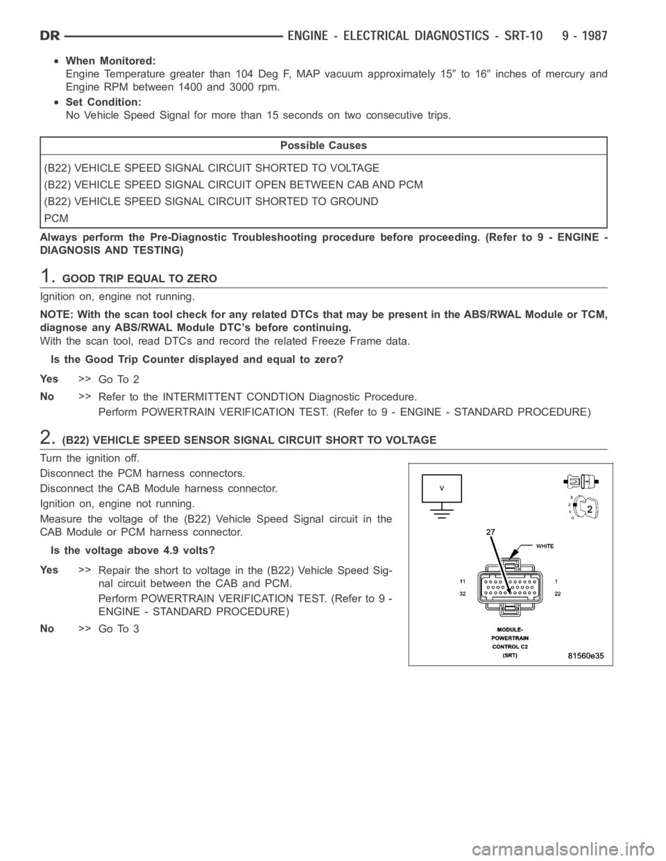
2.(B22) VEHICLE SPEED SENSOR SIGNAL CIRCUIT SHORT TO VOLTAGE
Turn the ignition off.
Disconnect the PCM harness connectors.
Disconnect the CAB Module harness connector.
Ignition on, engine not running.
Measure the voltage of the (B22) Vehicle Speed Signal circuit in the
CAB Module or PCM harness connector.
Is the voltage above 4.9 volts?
Ye s>>
Repair the short to voltage in the (B22) Vehicle Speed Sig-
nal circuit between the CAB and PCM.
Perform POWERTRAIN VERIFICATION TEST. (Refer to 9 -
ENGINE - STANDARD PROCEDURE)
No>>
Go To 3