Page 1664 of 5267
7. Position the secondary chain onto the camshaft drive gear, making sure one marked chain link is on either side
of the V8 mark on the gear (2) and position the gear onto the camshaft.
8. Install the camshaft drive gear retaining bolt.
9. Install the right side secondary chain guide (Refer to 9 - ENGINE/VALVE TIMING/TIMING BELT / CHAIN COV-
ER(S) - INSTALLATION).
10. Install the right side cylinder head access plug (1).
11. Re-set and install the right side secondary chain
tensioner.
Page 1665 of 5267
12. Remove Special Tool 8515 (6).
13. Install the timing chain cover (Refer to 9 -
ENGINE/VALVE TIMING/TIMING BELT / CHAIN
COVER(S) - INSTALLATION).
14. Install the crankshaft damper (Refer to 9 -
ENGINE/ENGINE BLOCK/VIBRATION DAMPER -
INSTALLATION).
15. Install accessory drive belt (Refer to 7 - COOL-
ING/ACCESSORY DRIVE/DRIVE BELTS -
INSTALLATION).
16. Install the fan shroud.
17. Install the cylinder head cover (1) (Refer to 9 -
ENGINE/CYLINDER HEAD/CYLINDER HEAD
COVER(S) - INSTALLATION).
18. Install the intake manifold (Refer to 9 - ENGINE/
MANIFOLDS/INTAKE MANIFOLD - INSTALLA-
TION).
19. Install oil fill housing onto cylinder head.
20. Refill the cooling system (Refer to 7 - COOLING -
STANDARD PROCEDURE).
21. Raise the vehicle.
22. Install the exhaust pipe onto the right exhaust
manifold.
23. Lower the vehicle.
24. Reconnect battery negitive cable.
25. Start the engine and check for leaks.
Page 1706 of 5267
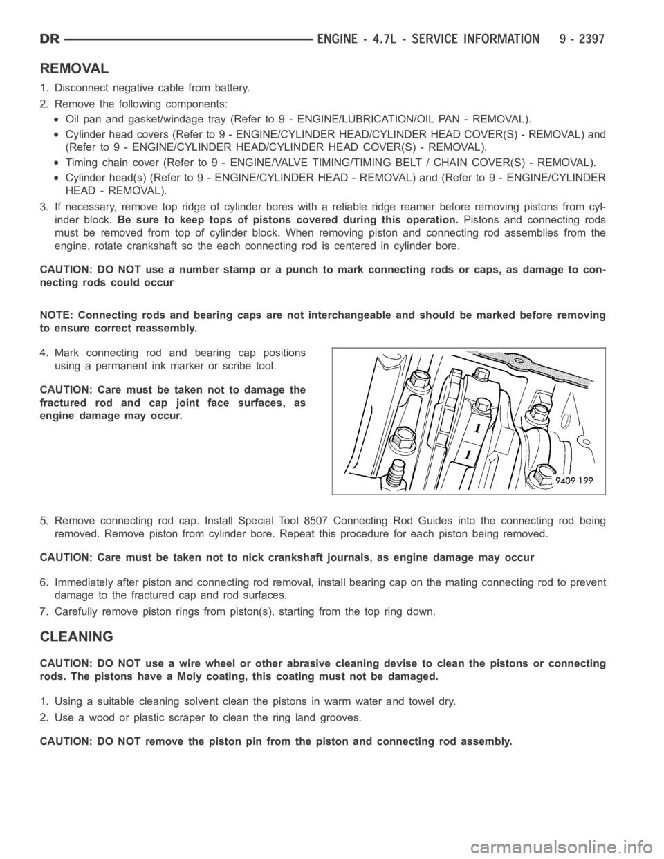
REMOVAL
1. Disconnect negative cable from battery.
2. Remove the following components:
Oil pan and gasket/windage tray (Refer to 9 - ENGINE/LUBRICATION/OIL PAN -REMOVAL).
Cylinder head covers (Refer to 9 - ENGINE/CYLINDER HEAD/CYLINDER HEAD COVER(S) - REMOVAL) and
(Refer to 9 - ENGINE/CYLINDER HEAD/CYLINDER HEAD COVER(S) - REMOVAL).
Timing chain cover (Refer to 9 - ENGINE/VALVE TIMING/TIMING BELT / CHAIN COVER(S) - REMOVAL).
Cylinder head(s) (Refer to 9 - ENGINE/CYLINDER HEAD - REMOVAL) and (Refer to 9 - ENGINE/CYLINDER
HEAD - REMOVAL).
3. If necessary, remove top ridge of cylinder bores with a reliable ridge reamer before removing pistons from cyl-
inder block.Be sure to keep tops of pistons covered during this operation.Pistons and connecting rods
must be removed from top of cylinder block. When removing piston and connecting rod assemblies from the
engine, rotate crankshaft so the each connecting rod is centered in cylinder bore.
CAUTION: DO NOT use a number stamp or a punch to mark connecting rods or caps,as damage to con-
necting rods could occur
NOTE: Connecting rods and bearing caps are not interchangeable and shouldbe marked before removing
to ensure correct reassembly.
4. Mark connecting rod and bearing cap positions
using a permanent ink marker or scribe tool.
CAUTION: Care must be taken not to damage the
fractured rod and cap joint face surfaces, as
engine damage may occur.
5. Remove connecting rod cap. Install Special Tool 8507 Connecting Rod Guides into the connecting rod being
removed. Remove piston from cylinder bore. Repeat this procedure for eachpiston being removed.
CAUTION: Care must be taken not to nick crankshaft journals, as engine damage may occur
6. Immediately after piston and connecting rod removal, install bearing cap on the mating connecting rod to prevent
damage to the fractured cap and rod surfaces.
7. Carefully remove piston rings from piston(s), starting from the top ring down.
CLEANING
CAUTION: DO NOT use a wire wheel or other abrasive cleaning devise to clean the pistons or connecting
rods. The pistons have a Moly coating, this coating must not be damaged.
1. Using a suitable cleaning solvent clean the pistons in warm water and towel dry.
2. Use a wood or plastic scraper to clean the ring land grooves.
CAUTION: DO NOT remove the piston pin from the piston and connecting rod assembly.
Page 1708 of 5267
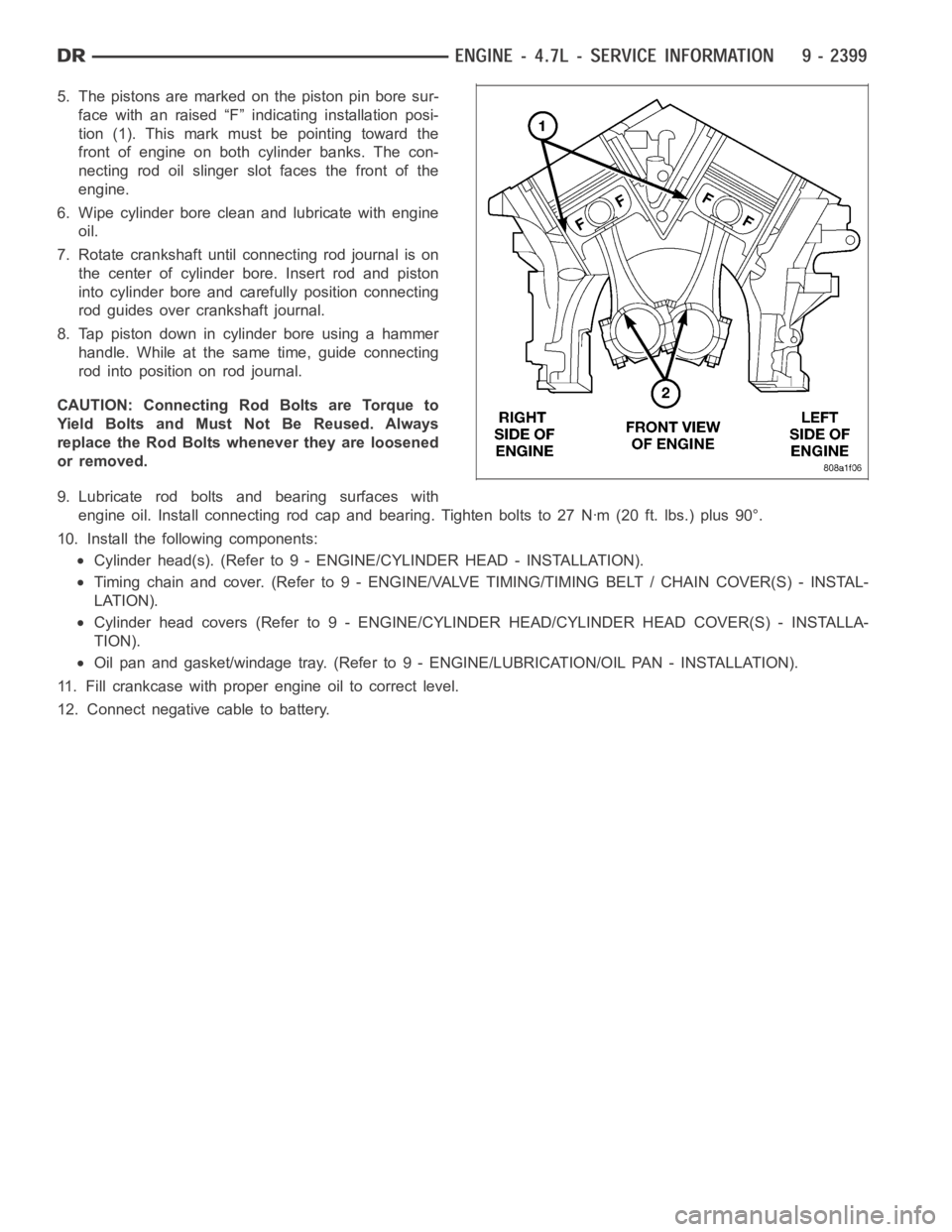
5. The pistons are marked on the piston pin bore sur-
face with an raised “F” indicating installation posi-
tion (1). This mark must be pointing toward the
front of engine on both cylinder banks. The con-
necting rod oil slinger slot faces the front of the
engine.
6. Wipe cylinder bore clean and lubricate with engine
oil.
7. Rotate crankshaft until connecting rod journal is on
the center of cylinder bore. Insert rod and piston
into cylinder bore and carefully position connecting
rod guides over crankshaft journal.
8. Tap piston down in cylinder bore using a hammer
handle. While at the same time, guide connecting
rodintopositiononrodjournal.
CAUTION: Connecting Rod Bolts are Torque to
Yield Bolts and Must Not Be Reused. Always
replace the Rod Bolts whenever they are loosened
or removed.
9. Lubricate rod bolts and bearing surfaces with
engine oil. Install connecting rod cap and bearing. Tighten bolts to 27 Nꞏm(20 ft. lbs.) plus 90°.
10. Install the following components:
Cylinder head(s). (Refer to 9 - ENGINE/CYLINDER HEAD - INSTALLATION).
Timing chain and cover. (Refer to 9 - ENGINE/VALVE TIMING/TIMING BELT / CHAIN COVER(S) - INSTAL-
LATION).
Cylinderheadcovers(Referto9-ENGINE/CYLINDER HEAD/CYLINDER HEAD COVER(S) - INSTALLA-
TION).
Oil pan and gasket/windage tray. (Refer to 9 - ENGINE/LUBRICATION/OIL PAN- INSTALLATION).
11. Fill crankcase with proper engine oil to correct level.
12. Connect negative cable to battery.
Page 1729 of 5267
PUMP - ENGINE OIL
REMOVAL
1. Remove the oil pan and pick-up tube (Refer to 9 - ENGINE/LUBRICATION/OILPA N - R E M O VA L ) .
2. Remove the timing chain cover (Refer to 9 - ENGINE/VALVE TIMING/TIMING BELT / CHAIN COVER(S) -
REMOVAL).
3. Remove the timing chains and tensioners (Refer to 9 - ENGINE/VALVE TIMING/TIMING BELT/CHAIN AND
SPROCKETS - REMOVAL).
4. Remove the four bolts, primary timing chain tensioner and the oil pump.
DISASSEMBLY
1. Remove oil pump cover screws and lift off cover plate.
2. Remove pump inner and outer rotors.
NOTE: Once the oil pressure relief valve, cup plug, and pin are removed, thepump assembly must be
replaced.
3. If it is necessary to remove the pressure relief valve, drive the roll pinfrom pump housing and remove cup plug,
spring and valve.
CLEANING
1. Wash all parts in a suitable solvent.
INSPECTION
CAUTION: Oil pump pressure relief valve and
spring should not be removed from the oil pump.
If these components are disassembled and or
removed from the pump the entire oil pump
assembly must be replaced.
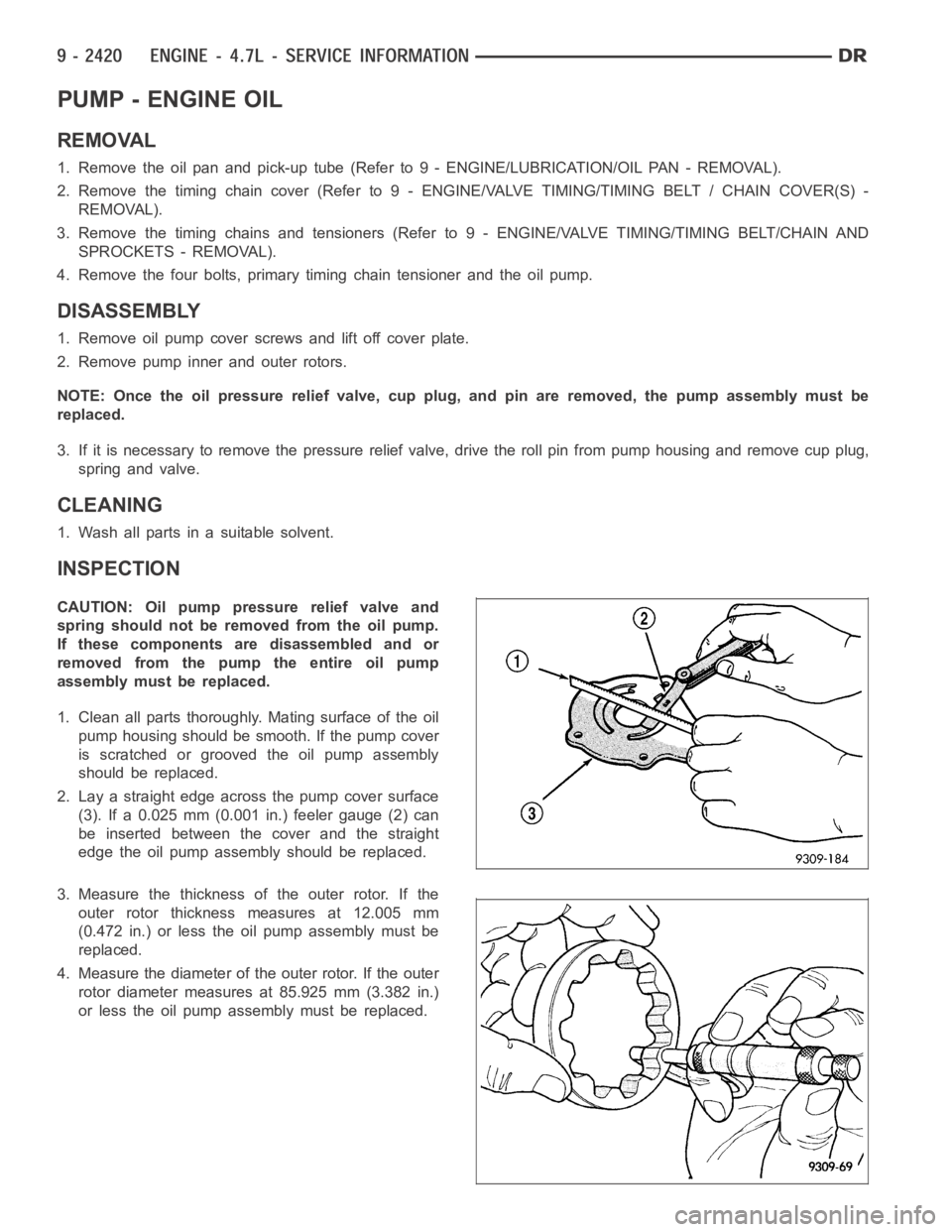
1. Clean all parts thoroughly. Mating surface of the oil
pump housing should be smooth. If the pump cover
is scratched or grooved the oil pump assembly
should be replaced.
2. Lay a straight edge across the pump cover surface
(3). If a 0.025 mm (0.001 in.) feeler gauge (2) can
be inserted between the cover and the straight
edge the oil pump assembly should be replaced.
3. Measure the thickness of the outer rotor. If the
outer rotor thickness measures at 12.005 mm
(0.472 in.) or less the oil pump assembly must be
replaced.
4. Measure the diameter of the outer rotor. If the outer
rotor diameter measures at 85.925 mm (3.382 in.)
or less the oil pump assembly must be replaced.
Page 1731 of 5267
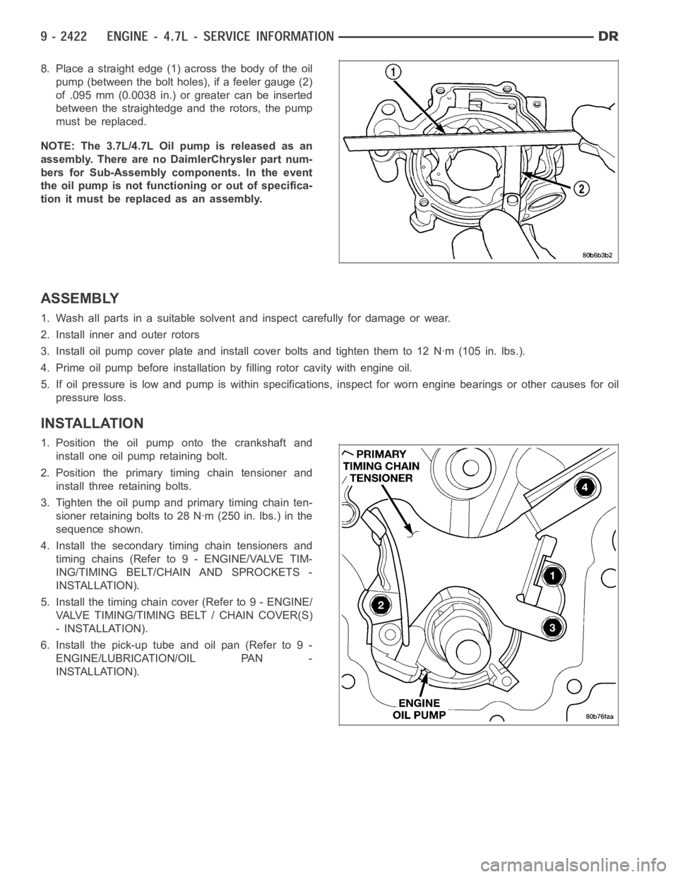
8. Place a straight edge (1) across the body of the oil
pump (between the bolt holes), if a feeler gauge (2)
of .095 mm (0.0038 in.) or greater can be inserted
between the straightedge and the rotors, the pump
must be replaced.
NOTE: The 3.7L/4.7L Oil pump is released as an
assembly. There are no DaimlerChrysler part num-
bers for Sub-Assembly components. In the event
the oil pump is not functioning or out of specifica-
tion it must be replaced as an assembly.
ASSEMBLY
1. Wash all parts in a suitable solvent and inspect carefully for damage or wear.
2. Install inner and outer rotors
3. Install oil pump cover plate and install cover bolts and tighten them to 12Nꞏm(105in.lbs.).
4. Prime oil pump before installation by filling rotor cavity with engine oil.
5. If oil pressure is low and pump is within specifications, inspect for worn engine bearings or other causes for oil
pressure loss.
INSTALLATION
1. Position the oil pump onto the crankshaft and
install one oil pump retaining bolt.
2. Position the primary timing chain tensioner and
install three retaining bolts.
3. Tighten the oil pump and primary timing chain ten-
sioner retaining bolts to 28 Nꞏm (250 in. lbs.) in the
sequence shown.
4. Install the secondary timing chain tensioners and
timing chains (Refer to 9 - ENGINE/VALVE TIM-
ING/TIMING BELT/CHAIN AND SPROCKETS -
INSTALLATION).
5. Install the timing chain cover (Refer to 9 - ENGINE/
VALVE TIMING/TIMING BELT / CHAIN COVER(S)
- INSTALLATION).
6. Install the pick-up tube and oil pan (Refer to 9 -
ENGINE/LUBRICATION/OIL PAN -
INSTALLATION).
Page 1740 of 5267
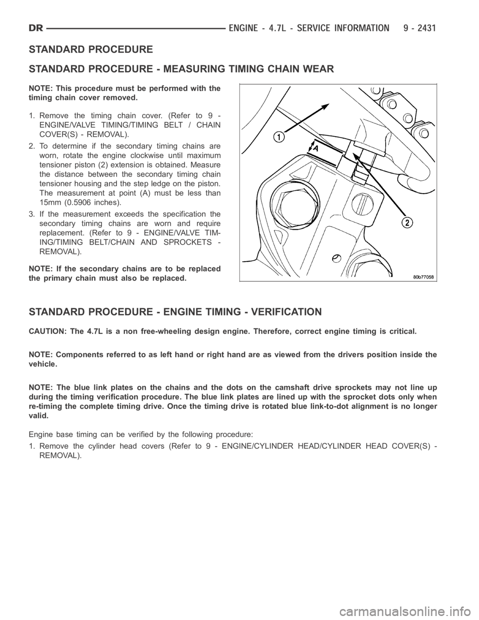
STANDARD PROCEDURE
STANDARD PROCEDURE - MEASURING TIMING CHAIN WEAR
NOTE: This procedure must be performed with the
timing chain cover removed.
1.Removethetimingchaincover.(Referto9-
ENGINE/VALVE TIMING/TIMING BELT / CHAIN
COVER(S) - REMOVAL).
2. To determine if the secondary timing chains are
worn, rotate the engine clockwise until maximum
tensioner piston (2) extension is obtained. Measure
the distance between the secondary timing chain
tensioner housing and the step ledge on the piston.
The measurement at point (A) must be less than
15mm (0.5906 inches).
3. If the measurement exceeds the specification the
secondary timing chains are worn and require
replacement. (Refer to 9 - ENGINE/VALVE TIM-
ING/TIMING BELT/CHAIN AND SPROCKETS -
REMOVAL).
NOTE: If the secondary chains are to be replaced
the primary chain must also be replaced.
STANDARD PROCEDURE - ENGINE TIMING - VERIFICATION
CAUTION: The 4.7L is a non free-wheeling design engine. Therefore, correct engine timing is critical.
NOTE: Components referred to as left hand or right hand are as viewed from thedriverspositioninsidethe
vehicle.
NOTE: The blue link plates on the chains and the dots on the camshaft drive sprockets may not line up
during the timing verification procedure. The blue link plates are lined up with the sprocket dots only when
re-timing the complete timing drive.Once the timing drive is rotated bluelink-to-dot alignment is no longer
valid.
Engine base timing can be verified by the following procedure:
1. Remove the cylinder head covers (Refer to 9 - ENGINE/CYLINDER HEAD/CYLINDERHEADCOVER(S)-
REMOVAL).
Page 1745 of 5267
COVER - TIMING
REMOVAL
1. Disconnect the battery negative cable.
2. Drain cooling system (Refer to 7 - COOLING -
STANDARD PROCEDURE).
3. Disconnect both heater hoses at timing cover.
4. Disconnect lower radiator hose at engine.
5. Remove crankshaft damper (Refer to 9 - ENGINE/
ENGINE BLOCK/VIBRATION DAMPER -
REMOVAL).
6. Remove accessory drive belt tensioner assembly
(1).
7. Remove the generator and A/C compressor.
CAUTION:The4.7LengineusesanRTVsealer
instead of a gasket to seal the front cover to the
engine block, from the factory. For service, Mopar
Grey Engine RTV sealant must be substituted.
NOTE: It is not necessary to remove the water
pump for timing cover removal.
8. Remove the bolts holding the timing cover to
engine block.
9. Remove cover.