Page 1837 of 5267
6. Remove the timing chain cover (Refer to 9 - ENGINE/VALVE TIMING/TIMING BELT / CHAIN COVER(S) -
REMOVAL).
7. Remove the oil pump (Refer to 9 - ENGINE/LUBRICATION/OIL PUMP - REMOVAL).
Page 1838 of 5267
8. Removethetimingdrive(2)(Referto9-ENGINE/
VALVE TIMING/TIMING BELT/CHAIN AND
SPROCKETS - REMOVAL).
9. Identify rod bearing caps before removal. Remove rod bearing caps with bearings.
10. Identify main bearing caps (1) before removal.
Page 1843 of 5267
12.Installtimingdrive(2)(Referto9-ENGINE/
VALVE TIMING/TIMING BELT/CHAIN AND
SPROCKETS - INSTALLATION).
13. Install oil pump (Refer to 9 - ENGINE/LUBRICATION/OIL PUMP - INSTALLATION).
Page 1844 of 5267
14. Install the timing chain cover (1) (Refer to 9 - ENGINE/VALVE TIMING/TIMING BELT / CHAIN COVER(S) -
INSTALLATION).
15. Install the rear main seal and retainer (Refer to 9
- ENGINE/ENGINE BLOCK/CRANKSHAFT REAR
OIL SEAL RETAINE - INSTALLATION).
16. Install the windage tray/oil pan gasket.
17. Install the oil pick up tube.
18. Install the oil pan (Refer to 9 - ENGINE/LUBRICA-
TION/OIL PAN - INSTALLATION).
19. Install the vibration damper (Refer to 9 - ENGINE/
ENGINE BLOCK/VIBRATION DAMPER - INSTAL-
LATION).
20. Install the engine (Refer to 9 - ENGINE -
INSTALLATION).
Page 1856 of 5267

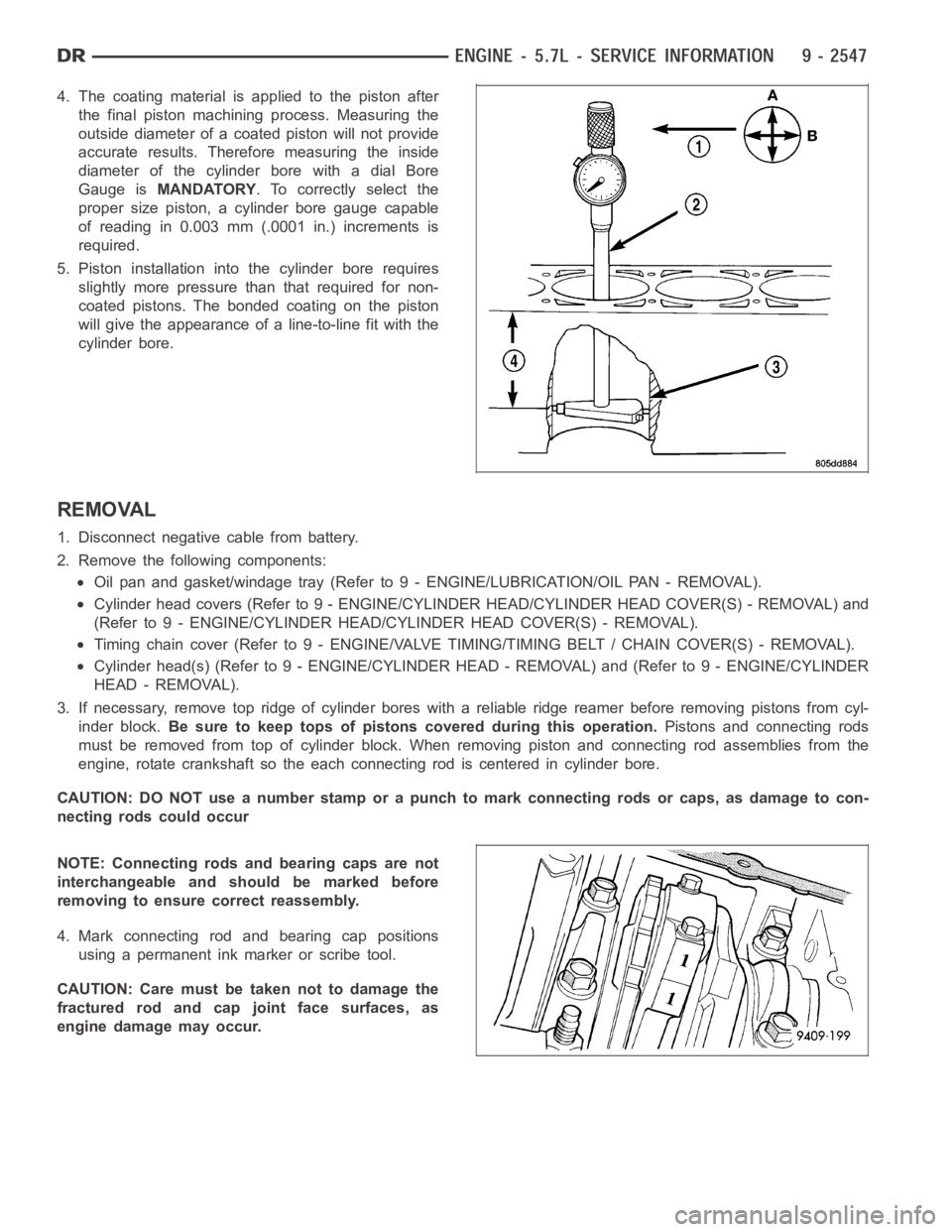
4. The coating material is applied to the piston after
the final piston machining process. Measuring the
outside diameter of a coated piston will not provide
accurate results. Therefore measuring the inside
diameter of the cylinder bore with a dial Bore
Gauge isMANDATORY. To correctly select the
proper size piston, a cylinder bore gauge capable
of reading in 0.003 mm (.0001 in.) increments is
required.
5. Piston installation intothe cylinder bore requires
slightly more pressure than that required for non-
coated pistons. The bonded coating on the piston
will give the appearance of a line-to-line fit with the
cylinder bore.
REMOVAL
1. Disconnect negative cable from battery.
2. Remove the following components:
Oil pan and gasket/windage tray (Refer to 9 - ENGINE/LUBRICATION/OIL PAN -REMOVAL).
Cylinder head covers (Refer to 9 - ENGINE/CYLINDER HEAD/CYLINDER HEAD COVER(S) - REMOVAL) and
(Refer to 9 - ENGINE/CYLINDER HEAD/CYLINDER HEAD COVER(S) - REMOVAL).
Timing chain cover (Refer to 9 - ENGINE/VALVE TIMING/TIMING BELT / CHAIN COVER(S) - REMOVAL).
Cylinder head(s) (Refer to 9 - ENGINE/CYLINDER HEAD - REMOVAL) and (Refer to 9 - ENGINE/CYLINDER
HEAD - REMOVAL).
3. If necessary, remove top ridge of cylinder bores with a reliable ridge reamer before removing pistons from cyl-
inder block.Be sure to keep tops of pistons covered during this operation.Pistons and connecting rods
must be removed from top of cylinder block. When removing piston and connecting rod assemblies from the
engine, rotate crankshaft so the each connecting rod is centered in cylinder bore.
CAUTION: DO NOT use a number stamp or a punch to mark connecting rods or caps,as damage to con-
necting rods could occur
NOTE: Connecting rods and bearing caps are not
interchangeable and should be marked before
removing to ensure correct reassembly.
4. Mark connecting rod and bearing cap positions
using a permanent ink marker or scribe tool.
CAUTION: Care must be taken not to damage the
fractured rod and cap joint face surfaces, as
engine damage may occur.
Page 1884 of 5267
REMOVAL
1. Remove the oil pan and pick-up tube (Refer to 9 - ENGINE/LUBRICATION/OILPA N - R E M O VA L ) .
2. Remove the timing chain cover (Refer to 9 - ENGINE/VALVE TIMING/TIMING BELT / CHAIN COVER(S) -
REMOVAL).
3. Remove the four bolts, and the oil pump.
CLEANING
1. Wash all parts in a suitable solvent.
Page 1886 of 5267
INSTALLATION
1. Position the oil pump onto the crankshaft and install the 4 oil pump retaining bolts.
2. Tighten the oil pump retaining bolts to 28 Nꞏm (250 in. lbs.).
3. Install the timing chain cover (Refer to 9 - ENGINE/VALVE TIMING/TIMINGBELT / CHAIN COVER(S) - INSTAL-
LATION).
4. Install the pick-up tube and oil pan (Refer to 9 - ENGINE/LUBRICATION/OIL PAN - INSTALLATION).
Page 1892 of 5267
COVER - TIMING
REMOVAL
1. Disconnect the battery negative cable.
2. Remove the engine cover (1).
3. Remove air cleaner assembly.
4. Drain cooling system.
5. Remove accessory drive belt.
6. Remove fan and fan drive assembly (Refer to 7 -
COOLING/ENGINE/FAN DRIVE VISCOUS
CLUTCH - REMOVAL).
7. Remove coolant bottle and washer bottle.
8. Remove fan shroud.
NOTE: It is not necessary to disconnect A/C lines
or discharge freon.
9. Remove A/C compressor and set aside.
10. Remove the generator.
11. Remove upper radiator hose.
12. Disconnect both heater hoses at timing cover.
13. Disconnect lower radiator hose at engine.
14. Remove accessory drive belt tensioner and both
idler pulleys.
15. Remove crankshaft damper (2) (Refer to 9 -
ENGINE/ENGINE BLOCK/VIBRATION DAMPER -
REMOVAL).
NOTE: Do not remove the hoses from the power
steering pump.
16. Remove power steering pump and set aside.