2006 DODGE RAM SRT-10 timing belt
[x] Cancel search: timing beltPage 1894 of 5267
INSTALLATION
1. Clean timing chain cover and block surface.
NOTE: Always install a new gasket on timing cover.
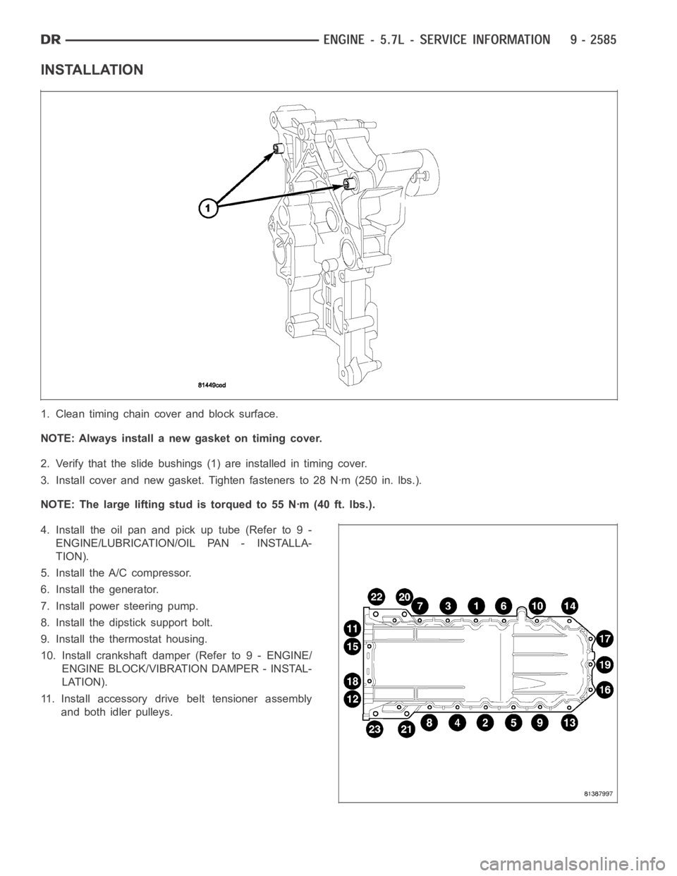
2. Verify that the slide bushings (1) are installed in timing cover.
3. Install cover and new gasket. Tighten fasteners to 28 Nꞏm (250 in. lbs.).
NOTE: The large lifting stud is torqued to 55 Nꞏm (40 ft. lbs.).
4. Install the oil pan and pick up tube (Refer to 9 -
ENGINE/LUBRICATION/OIL PAN - INSTALLA-
TION).
5. Install the A/C compressor.
6. Install the generator.
7. Install power steering pump.
8. Install the dipstick support bolt.
9. Install the thermostat housing.
10. Install crankshaft damper (Refer to 9 - ENGINE/
ENGINE BLOCK/VIBRATION DAMPER - INSTAL-
LATION).
11. Install accessory drive belt tensioner assembly
and both idler pulleys.
Page 1901 of 5267
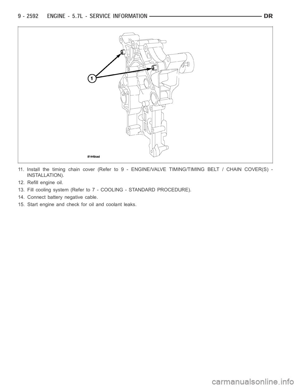
11. Install the timing chain cover (Refer to 9 - ENGINE/VALVE TIMING/TIMING BELT / CHAIN COVER(S) -
INSTALLATION).
12. Refill engine oil.
13. Fill cooling system (Refer to 7 - COOLING - STANDARD PROCEDURE).
14. Connect battery negative cable.
15. Start engine and check for oil and coolant leaks.
Page 1966 of 5267
CAMSHAFT & BEARINGS (IN BLOCK)
REMOVAL
CAMSHAFT BEARINGS
NOTE: Measure the diameter of each bore. If the camshaft bore for the cam bushing is worn beyond the
limit, install a new service bushing. Inspect the rest of the camshaft bores for damage or excessive wear.If
the bores without a bushing are worn beyond the limit, the engine must be removed for machining and
installation of service bushings. If badly worn, replace the cylinder block.
1. Remove the camshaft (Refer to 9 - ENGINE/ENGINE BLOCK/CAMSHAFT & BEARINGS (IN BLOCK) -
REMOVAL).
2. Remove the bushing from the No.1 bore.
3. Mark the cylinder block so you can align the oil hole in the cylinder blockwith the oil hole in the bushing.
CAMSHAFT
1. Disconnect both battery negative cables.
2. Recover A/C refrigerant (if A/C equipped) (Refer to 24 - HEATING & AIR CONDITIONING/PLUMBING - STAN-
DARD PROCEDURE).
3. Raise vehicle on hoist.
4. Drain engine coolant into container suitable for re-use (Refer to 7 - COOLING - STANDARD PROCEDURE).
5. Lower vehicle.
6. Remove radiator upper hose.
7. Remove viscous fan/drive/shroud assembly (Refer to 7 - COOLING/ENGINE/RADIATOR FAN - REMOVAL).
8. Disconnect the coolant recovery bottle hose from the radiator filler neck.
9. Disconnect lower radiator hose from radiator outlet.
10.Automatic Transmission models:Disconnect transmission oil cooler lines from front of radiator using Special
Tool 6931 (unless equipped with finger-release disconnect).
11. Remove radiator mounting screws and lift radiator out of engine compartment.
12. Remove upper radiator support panel.
13. If A/C equipped, disconnect A/C condenser refrigerant lines.
14. Disconnect charge air cooler piping from the cooler inlet and outlet.
15. Remove the two charge air cooler mounting bolts.
16. Remove charge air cooler (and A/C condenser if equipped) from vehicle.
17. Remove accessory drive belt (Refer to 7 - COOLING/ACCESSORY DRIVE/DRIVE BELTS - REMOVAL).
18. Remove accessory drive belt tensioner.
19. Remove the fan support/hub assembly.
20. Remove crankshaft damper and speed indicator ring (Refer to 9 - ENGINE/ENGINE BLOCK/VIBRATION
DAMPER - REMOVAL).
21. Remove the gear cover-to-housing bolts and gently pry the cover away from the housing, taking care not to mar
the sealing surfaces. Remove dust seal with cover.
22. Using Special Tool 7471–B Crankshaft Barring Tool, rotate the crankshaft to align the timing marks on the
crankshaft and the camshaft gears.
23. Remove the cylinder head cover (Refer to 9 - ENGINE/CYLINDER HEAD/CYLINDER HEAD COVER(S) -
REMOVAL).
Page 1971 of 5267
12. Install gear housing cover (Refer to 9 - ENGINE/VALVE TIMING/GEAR HOUSING COVER - INSTALLATION).
Install front crankshaft dust seal.
13. Install the crankshaft damper with the speed indicator ring (Refer to 9- ENGINE/ENGINE BLOCK/VIBRATION
DAMPER - INSTALLATION).
14. Install the fan support/hub assembly Refer to (Refer to 7 - COOLING/ENGINE/RADIATOR FAN - INSTALLA-
TION).
15. Install the power steering pump.
16. Install accessory drive belt tensioner. Torque bolt to 43 Nꞏm (32 ft. lbs.).
17. Install the accessory drive belt (Refer to 7 - COOLING/ACCESSORY DRIVE/DRIVE BELTS - INSTALLATION).
18. Install the charge air cooler (with a/c condenser and auxiliary transmission oil cooler, if equipped) and tighten
the mounting bolts to 2 Nꞏm (17 in. lbs.) torque.
19. Connect charge air cooler inlet and outlet pipes. Tighten clamps to 11 Nꞏm (95 in. lbs.) torque.
20. Install the radiator upper support panel.
21. Close radiator petcock and lower the radiator into the engine compartment. Tighten the mounting bolts to 11
Nꞏm (95 in. lbs.) torque.
22. Raise vehicle on hoist.
23. Connect radiator lower hose and install clamp.
24. Connect transmission auxiliary oil cooler lines (if equipped).
25. Lower vehicle.
26. Install the fandrive/shroud assembly. (Refer to 7 - COOLING/ENGINE/RADIATOR FAN - INSTALLATION)
27. Install the coolant recovery and windshield washer fluid reservoirs to the fan shroud.
28. Connect the coolant recovery hose to the radiator filler neck.
29. Add engine coolant (Refer to 7 - COOLING - STANDARD PROCEDURE).
30. Charge A/C system with refrigerant (if A/C equipped) (Refer to 24 - HEATING & AIR CONDITIONING/PLUMB-
ING - STANDARD PROCEDURE).
31. Connect the battery negative cables.
32. Start engine and check for engine oil and coolant leaks.
Page 2008 of 5267
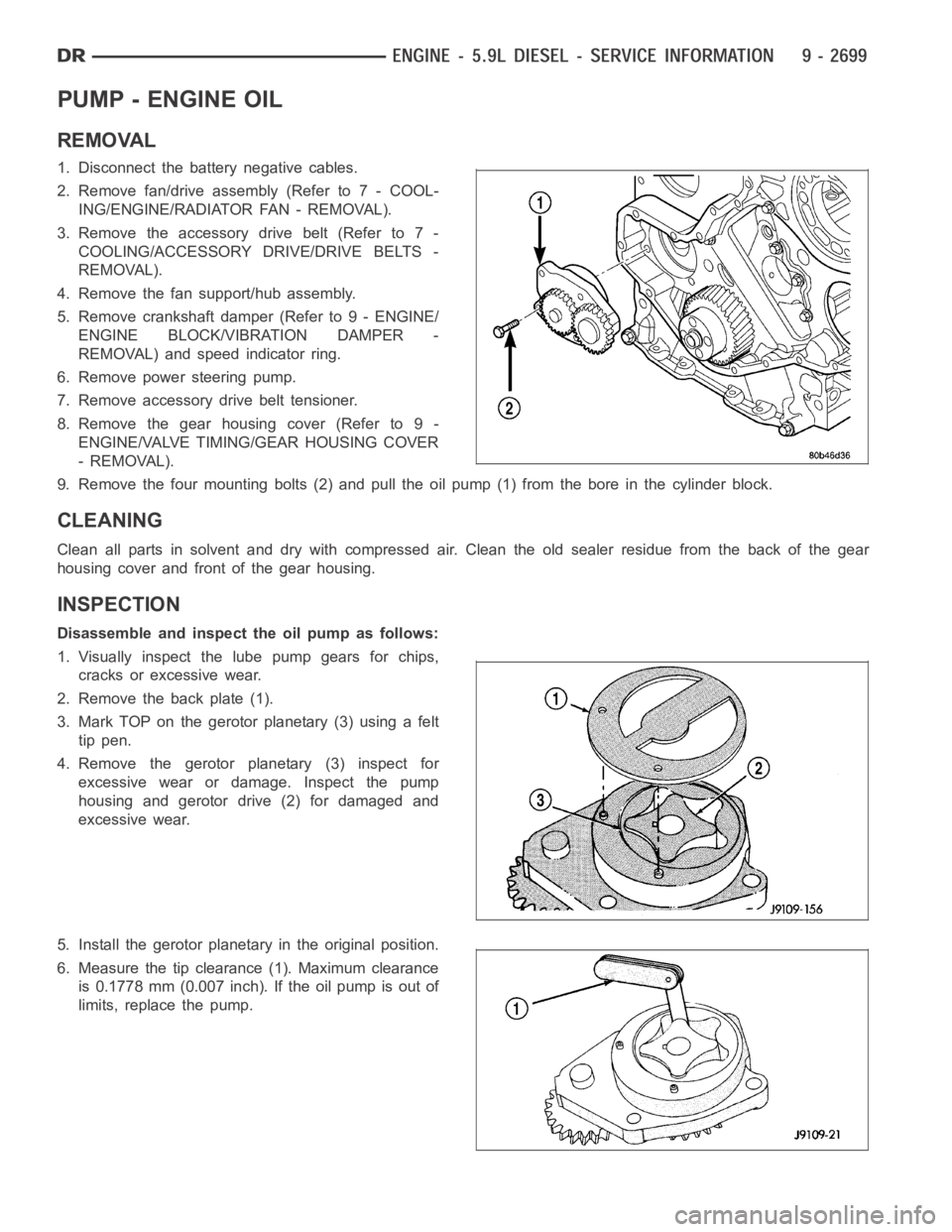
PUMP - ENGINE OIL
REMOVAL
1. Disconnect the battery negative cables.
2. Remove fan/drive assembly (Refer to 7 - COOL-
ING/ENGINE/RADIATOR FAN - REMOVAL).
3. Remove the accessory drive belt (Refer to 7 -
COOLING/ACCESSORY DRIVE/DRIVE BELTS -
REMOVAL).
4. Remove the fan support/hub assembly.
5. Remove crankshaft damper (Refer to 9 - ENGINE/
ENGINE BLOCK/VIBRATION DAMPER -
REMOVAL) and speed indicator ring.
6. Remove power steering pump.
7. Remove accessory drive belt tensioner.
8. Remove the gear housing cover (Refer to 9 -
ENGINE/VALVE TIMING/GEAR HOUSING COVER
- REMOVAL).
9. Remove the four mounting bolts (2) and pull the oil pump (1) from the bore in the cylinder block.
CLEANING
Clean all parts in solvent and dry with compressed air. Clean the old sealerresidue from the back of the gear
housing cover and front of the gear housing.
INSPECTION
Disassemble and inspect the oil pump as follows:
1. Visually inspect the lube pump gears for chips,
cracks or excessive wear.
2. Remove the back plate (1).
3. Mark TOP on the gerotor planetary (3) using a felt
tip pen.
4. Remove the gerotor planetary (3) inspect for
excessive wear or damage. Inspect the pump
housing and gerotor drive (2) for damaged and
excessive wear.
5. Install the gerotor planetary in the original position.
6. Measure the tip clearance (1). Maximum clearance
is 0.1778 mm (0.007 inch). If the oil pump is out of
limits, replace the pump.
Page 2010 of 5267
3. The back plate on the pump seats against the bot-
tom of the bore in the cylinder block. When the
pump is correctly installed, the flange on the pump
will not touch the cylinder block.
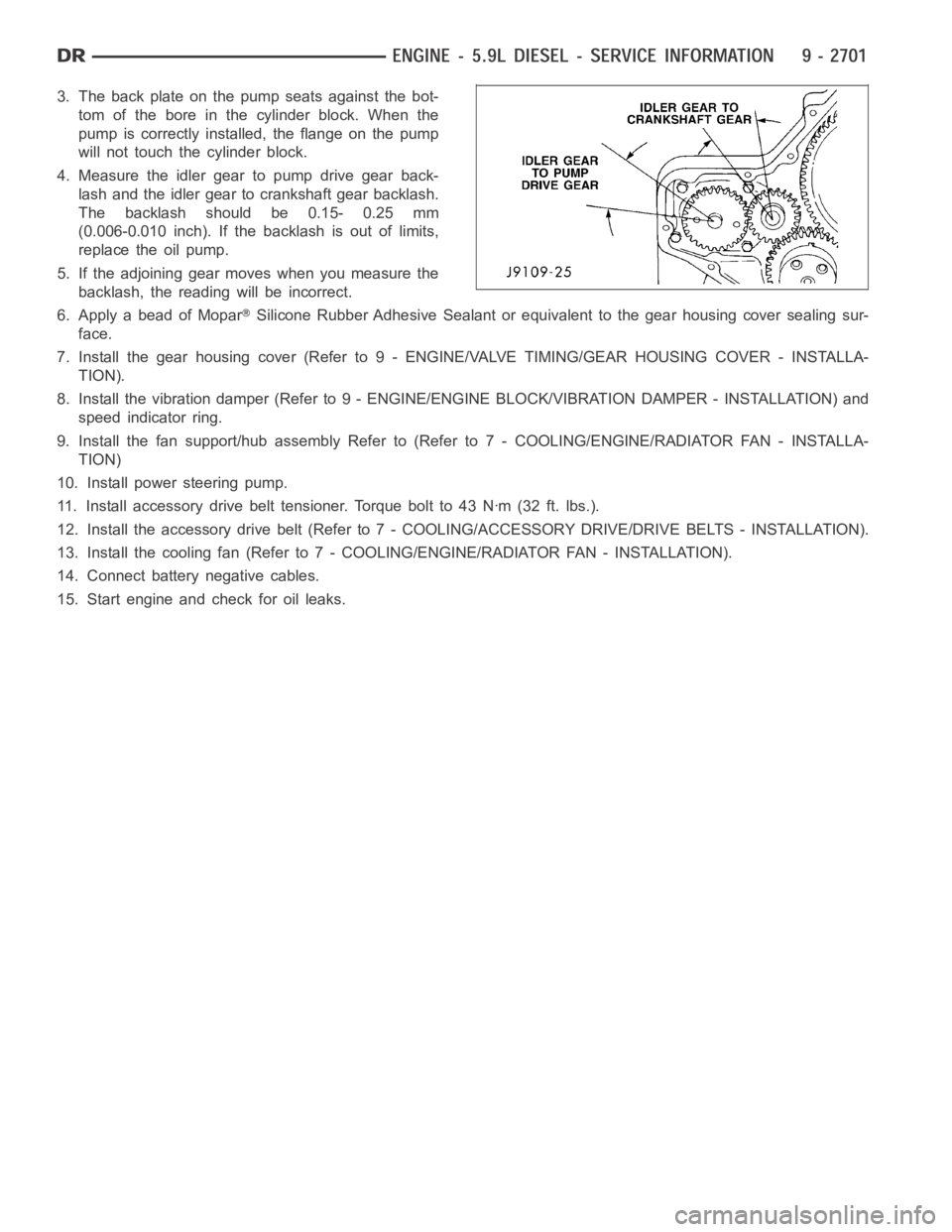
4. Measure the idler gear to pump drive gear back-
lash and the idler gear to crankshaft gear backlash.
The backlash should be 0.15- 0.25 mm
(0.006-0.010 inch). If the backlash is out of limits,
replace the oil pump.
5. If the adjoining gear moves when you measure the
backlash, the reading will be incorrect.
6. Apply a bead of Mopar
Silicone Rubber Adhesive Sealant or equivalent to the gear housing cover sealing sur-
face.
7. Install the gear housing cover (Refer to 9 - ENGINE/VALVE TIMING/GEAR HOUSING COVER - INSTALLA-
TION).
8. Install the vibration damper (Refer to 9 - ENGINE/ENGINE BLOCK/VIBRATION DAMPER - INSTALLATION) and
speed indicator ring.
9. Install the fan support/hub assemblyRefer to (Refer to 7 - COOLING/ENGINE/RADIATOR FAN - INSTALLA-
TION)
10. Install power steering pump.
11. Install accessory drive belt tensioner. Torque bolt to 43 Nꞏm (32 ft. lbs.).
12. Install the accessory drive belt (Refer to 7 - COOLING/ACCESSORY DRIVE/DRIVE BELTS - INSTALLATION).
13. Install the cooling fan (Refer to 7 - COOLING/ENGINE/RADIATOR FAN - INSTALLATION).
14. Connect battery negative cables.
15. Start engine and check for oil leaks.
Page 2019 of 5267
COVER - TIMING
REMOVAL
1. Disconnect both battery negative cables.
2. Raise vehicle on hoist.
3. Partially drain engine coolant into container suitable for re-use (Refer to 7 - COOLING - STANDARD PROCE-
DURE).
4. Lower vehicle.
5. Remove radiator upper hose.
6. Remove viscous fan/drive/shroud assembly (Refer to 7 - COOLING/ENGINE/RADIATOR FAN - REMOVAL).
7. Remove the accessory drive belt (Refer to 7 - COOLING/ACCESSORY DRIVE/DRIVE BELTS - REMOVAL).
8. Remove the cooling fan support/hub from the front of the engine.
9. Raise the vehicle on hoist.
10. Remove power steering pump.
11. Remove accessory drive belt tensioner.
12. Remove the crankshaft damper and speed indicator ring (Refer to 9 - ENGINE/ENGINE BLOCK/VIBRATION
DAMPER - REMOVAL).
13. Lower the vehicle.
14. Remove the gear cover-to-housing bolts and gently pry the cover away from the housing, taking care not to mar
the gasket surfaces.
INSTALLATION
1. Install a new front crankshaft oil seal.
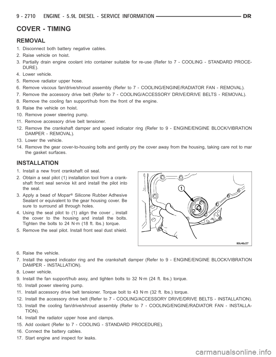
2. Obtain a seal pilot (1) installation tool from a crank-
shaft front seal service kit and install the pilot into
the seal.
3. Apply a bead of Mopar
Silicone Rubber Adhesive
Sealant or equivalent to the gear housing cover. Be
sure to surround all through holes.
4. Using the seal pilot to (1) align the cover , install
the cover to the housing and install the bolts.
Tighten the bolts to 24 Nꞏm (18 ft. lbs.) torque.
5. Remove the seal pilot. Install front seal dust shield.
6. Raise the vehicle.
7. Install the speed indicator ring and the crankshaft damper (Refer to 9 - ENGINE/ENGINE BLOCK/VIBRATION
DAMPER - INSTALLATION).
8. Lower vehicle.
9. Install the fan support/hub assy, and tighten bolts to 32 Nꞏm (24 ft. lbs.) torque.
10. Install power steering pump.
11. Install accessory drive belt tensioner. Torque bolt to 43 Nꞏm (32 ft. lbs.) torque.
12. Install the accessory drive belt (Refer to 7 - COOLING/ACCESSORY DRIVE/DRIVE BELTS - INSTALLATION).
13. Install the cooling fan/drive/shroud assembly (Refer to 7 - COOLING/ENGINE/RADIATOR FAN - INSTALLA-
TION).
14. Install the radiator upper hose and clamps.
15. Add coolant (Refer to 7 - COOLING - STANDARD PROCEDURE).
16. Connect the battery cables.
17. Start engine and inspect for leaks.
Page 2024 of 5267
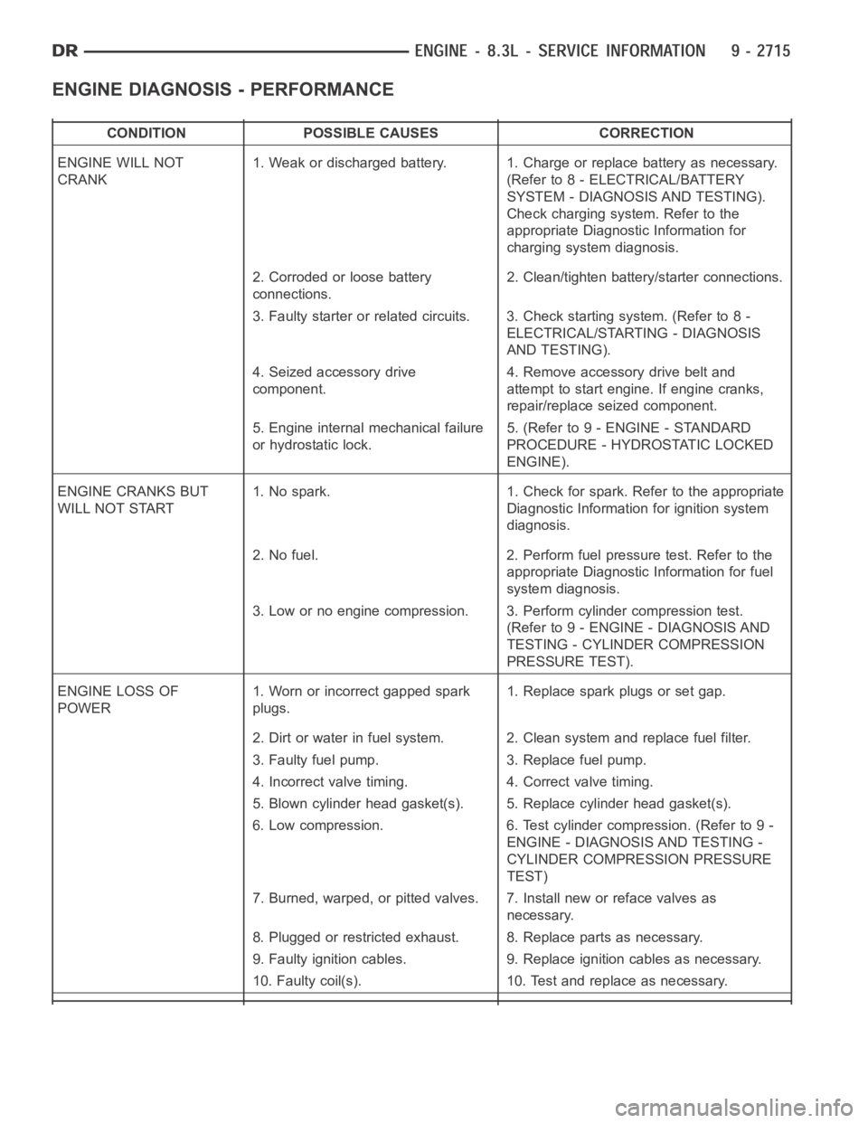
ENGINE DIAGNOSIS - PERFORMANCE
CONDITION POSSIBLE CAUSES CORRECTION
ENGINE WILL NOT
CRANK1. Weak or discharged battery. 1. Charge or replace battery as necessary.
(Refer to 8 - ELECTRICAL/BATTERY
SYSTEM - DIAGNOSIS AND TESTING).
Check charging system. Refer to the
appropriate Diagnostic Information for
charging system diagnosis.
2. Corroded or loose battery
connections.2. Clean/tighten battery/starter connections.
3. Faulty starter or related circuits. 3. Check starting system. (Refer to8-
ELECTRICAL/STARTING - DIAGNOSIS
AND TESTING).
4. Seized accessory drive
component.4. Remove accessory drive belt and
attempt to start engine. If engine cranks,
repair/replace seized component.
5. Engine internal mechanical failure
or hydrostatic lock.5. (Refer to 9 - ENGINE - STANDARD
PROCEDURE - HYDROSTATIC LOCKED
ENGINE).
ENGINE CRANKS BUT
WILL NOT START1. No spark. 1. Check for spark. Refer to the appropriate
Diagnostic Information for ignition system
diagnosis.
2. No fuel. 2. Perform fuel pressure test. Refer to the
appropriate Diagnostic Information for fuel
system diagnosis.
3. Low or no engine compression. 3. Perform cylinder compression test.
(Refer to 9 - ENGINE - DIAGNOSIS AND
TESTING - CYLINDER COMPRESSION
PRESSURE TEST).
ENGINE LOSS OF
POWER1. Worn or incorrect gapped spark
plugs.1. Replace spark plugs or set gap.
2. Dirt or water in fuel system. 2. Clean system and replace fuel filter.
3. Faulty fuel pump. 3. Replace fuel pump.
4. Incorrect valve timing. 4. Correct valve timing.
5. Blown cylinder head gasket(s). 5. Replace cylinder head gasket(s).
6. Low compression. 6. Test cylinder compression. (Refer to 9 -
ENGINE - DIAGNOSIS AND TESTING -
CYLINDER COMPRESSION PRESSURE
TEST)
7. Burned, warped, or pitted valves. 7. Install new or reface valves as
necessary.
8. Plugged or restricted exhaust. 8. Replace parts as necessary.
9. Faulty ignition cables. 9. Replace ignition cables as necessary.
10. Faulty coil(s). 10. Test and replace as necessary.