2006 DODGE RAM SRT-10 timing belt
[x] Cancel search: timing beltPage 1571 of 5267
REMOVAL
1. Disconnect negative cable from battery.
2. Remove the following components:
Oil pan and gasket/windage tray (Refer to 9 - ENGINE/LUBRICATION/OIL PAN -REMOVAL).
Cylinder head covers (Refer to 9 - ENGINE/CYLINDER HEAD/CYLINDER HEAD COVER(S) - REMOVAL) and
(Refer to 9 - ENGINE/CYLINDER HEAD/CYLINDER HEAD COVER(S) - REMOVAL).
Timing chain cover (Refer to 9 - ENGINE/VALVE TIMING/TIMING BELT / CHAIN COVER(S) - REMOVAL).
Cylinder head(s) (Refer to 9 - ENGINE/CYLINDER HEAD - REMOVAL) and (Refer to 9 - ENGINE/CYLINDER
HEAD - REMOVAL).
3. If necessary, remove top ridge of cylinder bores with a reliable ridge reamer before removing pistons from cyl-
inder block.Be sure to keep tops of pistons covered during this operation.Pistons and connecting rods
must be removed from top of cylinder block. When removing piston and connecting rod assemblies from the
engine, rotate crankshaft so the each connecting rod is centered in cylinder bore.
CAUTION: DO NOT use a number stamp or a punch to mark connecting rods or caps,as damage to con-
necting rods could occur
NOTE: Connecting rods and bearing caps are not interchangeable and shouldbe marked before removing
to ensure correct reassembly.
4. Mark connecting rod and bearing cap positions using a permanent ink marker or scribe tool.
CAUTION: Care must be taken not to damage the fractured rod and cap joint face surfaces, as engine dam-
age may occur.
5. Remove connecting rod cap. Install Special Tool 8507 Connecting Rod Guides into the connecting rod being
removed. Remove piston from cylinder bore. Repeat this procedure for eachpiston being removed.
CAUTION: Care must be taken not to nick crankshaft journals, as engine damage may occur
6. Immediately after piston and connecting rod removal, install bearing cap on the mating connecting rod to prevent
damage to the fractured cap and rod surfaces.
CLEANING
CAUTION: DO NOT use a wire wheel or other abrasive cleaning devise to clean the pistons or connecting
rods. The pistons have a Moly coating, this coating must not be damaged.
1. Using a suitable cleaning solvent clean the pistons in warm water and towel dry.
2. Use a wood or plastic scraper to clean the ring land grooves.
CAUTION: DO NOT remove the piston pin from the piston and connecting rod assembly.
INSPECTION
Check the connecting rod journal for excessive wear, taper and scoring (Refer to 9 - ENGINE/ENGINE BLOCK/
CONNECTING ROD BEARINGS - STANDARD PROCEDURE).
Check the connecting rod for signs of twist or bending.
Check the piston for taper and elliptical shape before it is fitted into thecylinder bore (Refer to 9 - ENGINE/ENGINE
BLOCK/PISTON & CONNECTING ROD - STANDARD PROCEDURE).
Check the piston for scoring, or scraping marks in the piston skirts. Checkthe ring lands for cracks and/or deteri-
oration.
Page 1572 of 5267
INSTALLATION
1. Before installing piston and connecting rod assem-
blies into the bore, install the piston rings.
2. Immerse the piston head and rings in clean engine
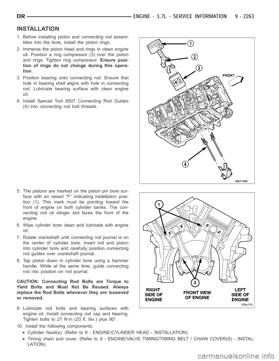
oil. Position a ring compressor (3) over the piston
and rings. Tighten ring compressor.Ensure posi-
tion of rings do not change during this opera-
tion.
3. Position bearing onto connecting rod. Ensure that
hole in bearing shell aligns with hole in connecting
rod. Lubricate bearing surface with clean engine
oil.
4. Install Special Tool 8507 Connecting Rod Guides
(4) into connecting rod bolt threads.
5. The pistons are marked on the piston pin bore sur-
face with an raised “F” indicating installation posi-
tion (1). This mark must be pointing toward the
front of engine on both cylinder banks. The con-
necting rod oil slinger slot faces the front of the
engine.
6. Wipe cylinder bore clean and lubricate with engine
oil.
7. Rotate crankshaft until connecting rod journal is on
the center of cylinder bore. Insert rod and piston
into cylinder bore and carefully position connecting
rod guides over crankshaft journal.
8. Tap piston down in cylinder bore using a hammer
handle. While at the same time, guide connecting
rodintopositiononrodjournal.
CAUTION: Connecting Rod Bolts are Torque to
Yield Bolts and Must Not Be Reused. Always
replace the Rod Bolts whenever they are loosened
or removed.
9. Lubricate rod bolts and bearing surfaces with
engine oil. Install connecting rod cap and bearing.
Tighten bolts to 27 Nꞏm (20 ft. lbs.) plus 90°.
10. Install the following components:
Cylinder head(s). (Refer to 9 - ENGINE/CYLINDER HEAD - INSTALLATION).
Timing chain and cover. (Refer to 9 - ENGINE/VALVE TIMING/TIMING BELT / CHAIN COVER(S) - INSTAL-
LATION).
Page 1594 of 5267
PUMP-ENGINE OIL
REMOVAL
1. Remove the oil pan and pick-up tube (Refer to 9 - ENGINE/LUBRICATION/OILPA N - R E M O VA L ) .
2. Remove the timing chain cover (Refer to 9 - ENGINE/VALVE TIMING/TIMING BELT / CHAIN COVER(S) -
REMOVAL).
3. Remove the timing chains and tensioners (Refer to 9 - ENGINE/VALVE TIMING/TIMING BELT/CHAIN AND
SPROCKETS - REMOVAL).
4. Remove the four bolts, primary timing chain tensioner and the oil pump.
DISASSEMBLY
1. Remove oil pump cover screws and lift off cover plate.
2. Remove pump inner and outer rotors.
NOTE: Once the oil pressure relief valve, cup plug, and pin are removed, thepump assembly must be
replaced.
3. If it is necessary to remove the pressure relief valve, drive the roll pinfrom pump housing and remove cup plug,
spring and valve.
INSPECTION
CAUTION: Oil pump pressure relief valve and
spring should not be removed from the oil pump.
If these components are disassembled and or
removed from the pump the entire oil pump
assembly must be replaced.
1. Clean all parts thoroughly. Mating surface of the oil
pump housing should be smooth. If the pump cover
is scratched or grooved the oil pump assembly
should be replaced.
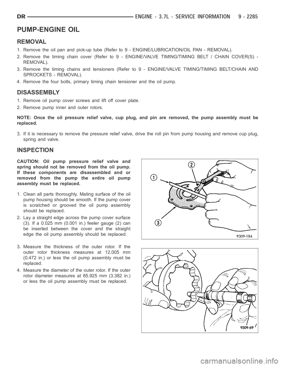
2. Lay a straight edge across the pump cover surface
(3). If a 0.025 mm (0.001 in.) feeler gauge (2) can
be inserted between the cover and the straight
edge the oil pump assembly should be replaced.
3. Measure the thickness of the outer rotor. If the
outer rotor thickness measures at 12.005 mm
(0.472 in.) or less the oil pump assembly must be
replaced.
4. Measure the diameter of the outer rotor. If the outer
rotor diameter measures at 85.925 mm (3.382 in.)
or less the oil pump assembly must be replaced.
Page 1596 of 5267
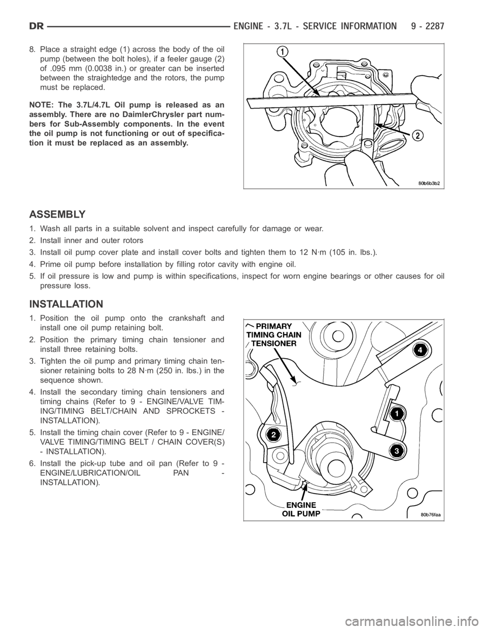
8. Place a straight edge (1) across the body of the oil
pump (between the bolt holes), if a feeler gauge (2)
of .095 mm (0.0038 in.) or greater can be inserted
between the straightedge and the rotors, the pump
must be replaced.
NOTE: The 3.7L/4.7L Oil pump is released as an
assembly. There are no DaimlerChrysler part num-
bers for Sub-Assembly components. In the event
the oil pump is not functioning or out of specifica-
tion it must be replaced as an assembly.
ASSEMBLY
1. Wash all parts in a suitable solvent and inspect carefully for damage or wear.
2. Install inner and outer rotors
3. Install oil pump cover plate and install cover bolts and tighten them to 12Nꞏm(105in.lbs.).
4. Prime oil pump before installation by filling rotor cavity with engine oil.
5. If oil pressure is low and pump is within specifications, inspect for worn engine bearings or other causes for oil
pressure loss.
INSTALLATION
1. Position the oil pump onto the crankshaft and
install one oil pump retaining bolt.
2. Position the primary timing chain tensioner and
install three retaining bolts.
3. Tighten the oil pump and primary timing chain ten-
sioner retaining bolts to 28 Nꞏm (250 in. lbs.) in the
sequence shown.
4. Install the secondary timing chain tensioners and
timing chains (Refer to 9 - ENGINE/VALVE TIM-
ING/TIMING BELT/CHAIN AND SPROCKETS -
INSTALLATION).
5. Install the timing chain cover (Refer to 9 - ENGINE/
VALVE TIMING/TIMING BELT / CHAIN COVER(S)
- INSTALLATION).
6. Install the pick-up tube and oil pan (Refer to 9 -
ENGINE/LUBRICATION/OIL PAN -
INSTALLATION).
Page 1607 of 5267
loads. Each tensioner also has a mechanical ratchet system that limits chain slack if the tensioner piston bleeds
down after engine shut down. The tensioner arms and guides also utilize nylon wear faces for low friction and long
wear. The secondary timing chains receive lubrication from a small orifice in the tensioners. This orifice is protected
from clogging by a fine mesh screen which is located on the back of the hydraulic tensioners.
STANDARD PROCEDURE
MEASURING TIMING CHAIN WEAR
NOTE: This procedure must be performed with the
timing chain cover removed.
1. Remove the timing chain cover (Refer to 9 -
ENGINE/VALVE TIMING/TIMING BELT/CHAIN
AND SPROCKETS - REMOVAL).
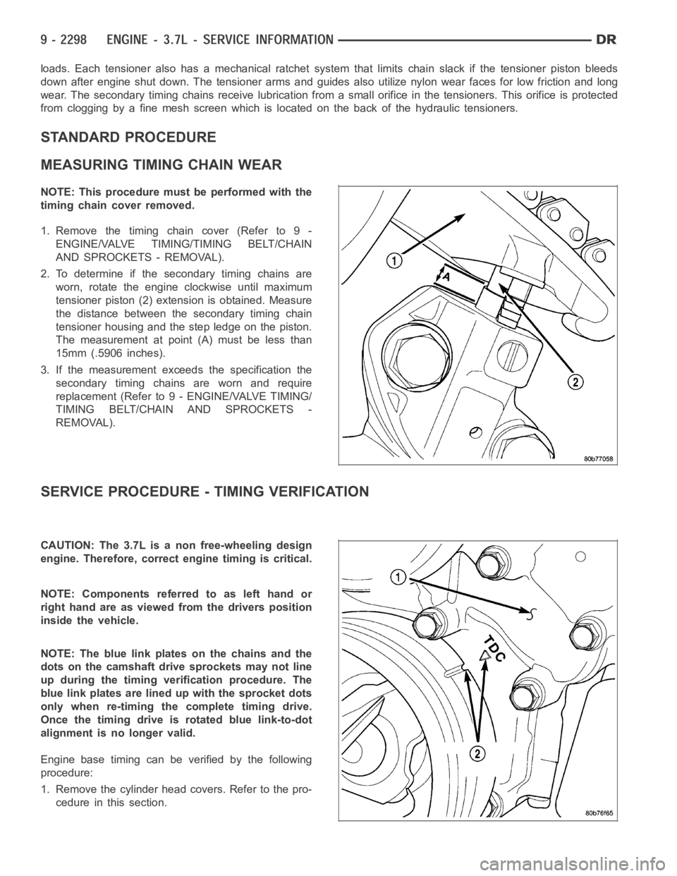
2. To determine if the secondary timing chains are
worn, rotate the engine clockwise until maximum
tensioner piston (2) extension is obtained. Measure
the distance between the secondary timing chain
tensioner housing and the step ledge on the piston.
The measurement at point (A) must be less than
15mm (.5906 inches).
3. If the measurement exceeds the specification the
secondary timing chains are worn and require
replacement (Refer to 9 - ENGINE/VALVE TIMING/
TIMING BELT/CHAIN AND SPROCKETS -
REMOVAL).
SERVICE PROCEDURE - TIMING VERIFICATION
CAUTION: The 3.7L is a non free-wheeling design
engine. Therefore, correct engine timing is critical.
NOTE:Componentsreferredtoaslefthandor
right hand are as viewed from the drivers position
inside the vehicle.
NOTE: The blue link plates on the chains and the
dots on the camshaft drive sprockets may not line
up during the timing verification procedure. The
blue link plates are lined up with the sprocket dots
only when re-timing the complete timing drive.
Once the timing drive is rotated blue link-to-dot
alignment is no longer valid.
Engine base timing can be verified by the following
procedure:
1. Remove the cylinder head covers. Refer to the pro-
cedure in this section.
Page 1614 of 5267
COVER-TIMING
REMOVAL
1. Disconnect the battery negative cable.
2. Drain cooling system (Refer to 7 - COOLING -
STANDARD PROCEDURE).
3. Remove electric cooling fan and fan shroud assem-
bly.
4. Remove fan and fan drive assembly (Refer to 7 -
COOLING/ENGINE/FAN DRIVE VISCOUS
CLUTCH - REMOVAL).
5. Disconnect both heater hoses at timing cover.
6. Disconnect lower radiator hose at engine.
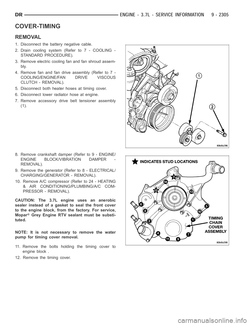
7. Remove accessory drive belt tensioner assembly
(1).
8. Remove crankshaft damper (Refer to 9 - ENGINE/
ENGINE BLOCK/VIBRATION DAMPER -
REMOVAL).
9. Remove the generator (Refer to 8 - ELECTRICAL/
CHARGING/GENERATOR - REMOVAL).
10. Remove A/C compressor (Refer to 24 - HEATING
& AIR CONDITIONING/PLUMBING/A/C COM-
PRESSOR - REMOVAL).
CAUTION: The 3.7L engine uses an anerobic
sealer instead of a gasket to seal the front cover
to the engine block, from the factory. For service,
Mopar
Grey Engine RTV sealant must be substi-
tuted.
NOTE: It is not necessary to remove the water
pump for timing cover removal.
11. Remove the bolts holding the timing cover to
engine block .
12. Remove the timing cover.
Page 1615 of 5267
INSTALLATION
CAUTION: Do not use oil based liquids to clean
timing cover or block surfaces. Use only rubbing
alcohol, along with plastic or wooden scrapers.
Use no wire brushes or abrasive wheels or metal
scrapers, or damage to surfaces could result.
1. Clean timing chain cover and block surface using
rubbing alcohol.
CAUTION: The 3.7L uses a special anerobic sealer
instead of a gasket to seal the timing cover to the
engine block, from the factory. For service repairs,
Mopar
Engine Grey RTV must be used as a sub-
stitute.
2. Inspect the water passage o-rings for any damage,
and replace as necessary.
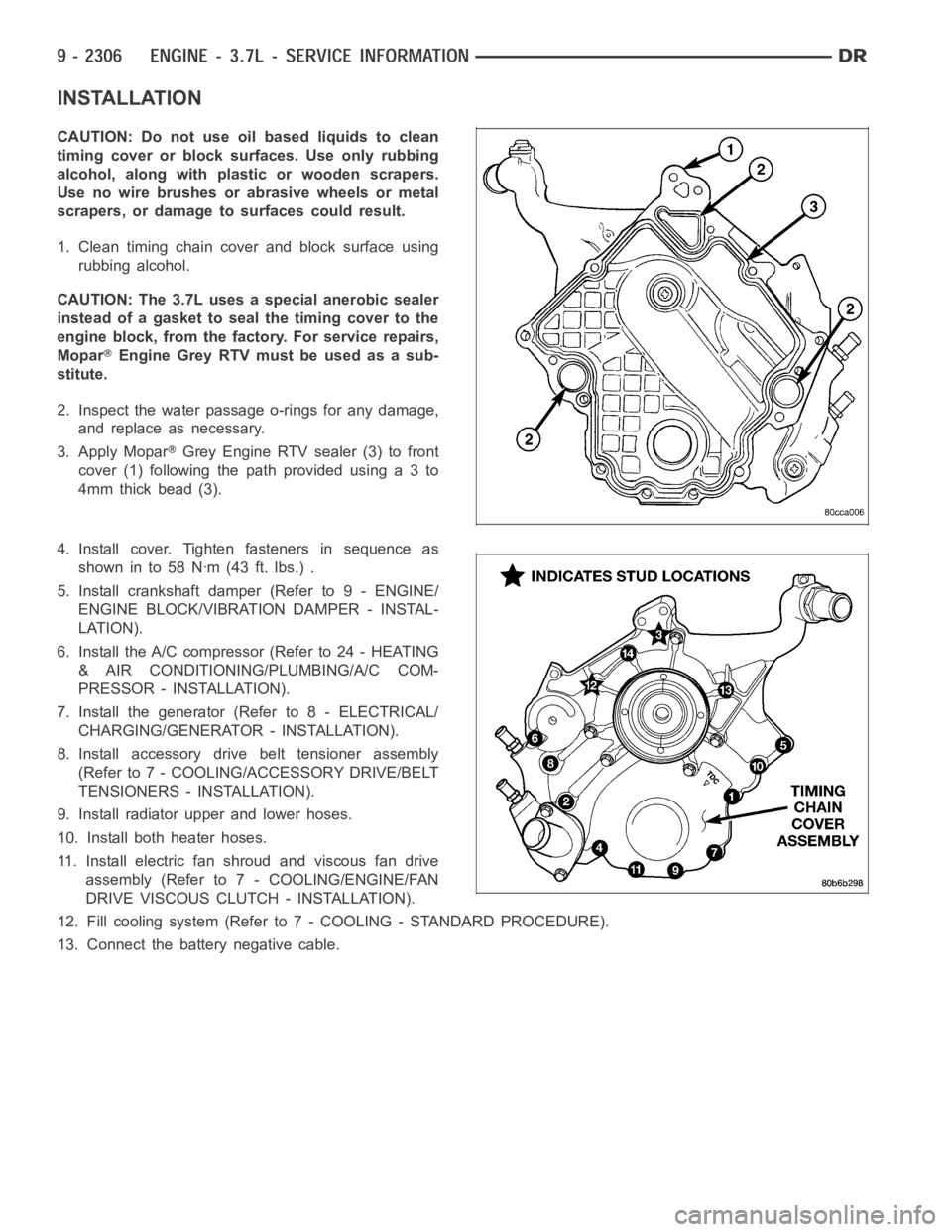
3. Apply Mopar
Grey Engine RTV sealer (3) to front
cover(1)followingthepathprovidedusinga3to
4mm thick bead (3).
4. Install cover. Tighten fasteners in sequence as
showninto58Nꞏm(43ft.lbs.).
5. Install crankshaft damper (Refer to 9 - ENGINE/
ENGINE BLOCK/VIBRATION DAMPER - INSTAL-
LATION).
6. Install the A/C compressor (Refer to 24 - HEATING
& AIR CONDITIONING/PLUMBING/A/C COM-
PRESSOR - INSTALLATION).
7. Install the generator (Refer to 8 - ELECTRICAL/
CHARGING/GENERATOR - INSTALLATION).
8. Install accessory drive belt tensioner assembly
(Refer to 7 - COOLING/ACCESSORY DRIVE/BELT
TENSIONERS - INSTALLATION).
9. Install radiator upper and lower hoses.
10. Install both heater hoses.
11. Install electric fan shroud and viscous fan drive
assembly (Refer to 7 - COOLING/ENGINE/FAN
DRIVE VISCOUS CLUTCH - INSTALLATION).
12. Fill cooling system (Refer to 7 - COOLING - STANDARD PROCEDURE).
13. Connect the battery negative cable.
Page 1617 of 5267
6. Remove power steering pump (Refer to 19 -
STEERING/PUMP - REMOVAL).
7. Remove access plug from left and right cylinder
heads for access to chain guide fasteners.
8. Remove the oil fill housing to gain access to the
right side tensioner arm fastener.
9. Remove crankshaft damper (Refer to 9 - ENGINE/
ENGINE BLOCK/VIBRATION DAMPER -
REMOVAL) and timing chain cover (Refer to 9 -
ENGINE/VALVE TIMING/TIMING BELT / CHAIN
COVER(S) - REMOVAL).
10. Collapse and pin primary chain tensioner.
CAUTION: Plate behind left secondary chain ten-
sioner could fall into oil pan. Therefore, cover pan
opening.
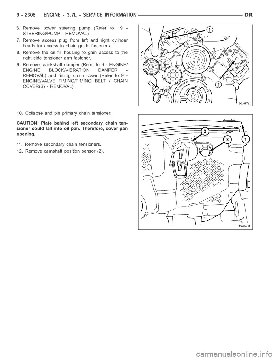
11. Remove secondary chain tensioners.
12. Remove camshaft position sensor (2).