2006 DODGE RAM SRT-10 check engine
[x] Cancel search: check enginePage 873 of 5267

When Monitored:
When the ignition is on.
Set Condition:
When the signal from the #2 intake air heater output does not match the signal from the #2 intake air heater
feedback.
Possible Causes
LOOSE CONNECTION
INTAKEAIRHEATERRELAY
SIGNAL CIRCUIT OPEN FROM RELAY TO ECM
SIGNAL CIRCUIT SHORTED TO BATTERY NEGATIVE
ECM
INTERMITTENT CONDITION
Always perform the Pre-Diagnostic Troubleshooting procedure before proceeding. (Refer to 9 - ENGINE -
DIAGNOSIS AND TESTING)
Diagnostic Test
1.RELAY CLICKING
Ignition on, engine not running.
With the scan tool, actuate the #1 Intake Air Heater.
Can you hear the Relay clicking?
Ye s>>
Go To 2
No>>
Go To 3
2.LOOSE CONNECTION
While the relay is clicking , wiggle the wiring harness and connectors.
Does this interrupt the clicking?
Ye s>>
Repair the poor connection.
Perform POWERTRAIN VERIFICATION TEST VER - 1 (DIESEL). (Refer to 8 - ELECTRICAL/ELEC-
TRONIC CONTROL MODULES/ENGINE CONTROL MODULE - DIAGNOSIS AND TESTING)
No>>
Go To 3
3.INTAKE AIR HEATER RELAY
Turn the ignition off.
Remove the Intake Air Heater #1 Relay.
Check connectors - Clean/repair as necessary.
Measure the resistance between the signal and return posts of the intake air heater relay.
Is the resistance between 15 and 25 Ohms?
Ye s>>
Go To 4
No>>
Replace the Intake Air Heater #1 relay.
Perform POWERTRAIN VERIFICATION TEST VER - 1 (DIESEL). (Refer to 8 - ELECTRICAL/ELEC-
TRONIC CONTROL MODULES/ENGINE CONTROL MODULE - DIAGNOSIS AND TESTING)
Page 874 of 5267

4.SIGNAL CIRCUIT OPEN FROM RELAY TO ECM
Disconnect the ECM harness connectors.
Check connectors - Clean/repair as necessary.
Measure the resistance of the intake air heater relay signal circuit between the ECM connector and the intake air
heater relay connector.
Is the resistance less than 10 Ohms?
Ye s>>
Go To 5
No>>
Repair the open signal circuit from PDC to ECM harness connector.
Perform POWERTRAIN VERIFICATION TEST VER - 1 (DIESEL). (Refer to 8 - ELECTRICAL/ELEC-
TRONIC CONTROL MODULES/ENGINE CONTROL MODULE - DIAGNOSIS AND TESTING)
5.RETURN CIRCUIT SHORTED TO BATTERY NEGATIVE
Measure the resistance of the return circuit between the intake air heaterrelay connector and battery negative.
I s resistance less than 10 ohms?
Ye s>>
Go To 6
No>>
Repair the return circuit shorted to battery negative.
6.SIGNAL CIRCUIT SHORTED TO BATTERY NEGATIVE
Measure the voltage between the signal circuit of the intake air heater relay and battery negative.
Is the voltage greater than 1 volts?
Ye s>>
Repair the signal circuit shorted to Battery negative.
Perform POWERTRAIN VERIFICATION TEST VER - 1 (DIESEL). (Refer to 8 - ELECTRICAL/ELEC-
TRONIC CONTROL MODULES/ENGINE CONTROL MODULE - DIAGNOSIS AND TESTING)
No>>
Go To 7
7.ECM
Reconnect the ECM harness connectors.
Disconnect the intake air heater relay signal wire and use a jumper to connect it to battery negative.
Turn the ignition on.
With the scan tool, read DTCs.
Did DTC P2608?
Ye s>>
Refer to the INTERMITTENT CONDITION Symptom (Diagnostic Procedure). (Refer to 9 - ENGINE -
DIAGNOSIS AND TESTING)
No>>
Replace the ECM.
Perform POWERTRAIN VERIFICATION TEST VER - 1 (DIESEL). (Refer to 8 - ELECTRICAL/ELEC-
TRONIC CONTROL MODULES/ENGINE CONTROL MODULE - DIAGNOSIS AND TESTING)
Page 876 of 5267

When Monitored:
When the ignition is on.
Set Condition:
When the signal from the #2 Intake Air Heater output does not match the signal from the #2 Intake Air Heater
feedback.
Possible Causes
LOOSE CONNECTION
INTAKEAIRHEATERRELAY
SIGNAL CIRCUIT SHORTED TO BATTERY NEGATIVE
ECM
INTERMITTENT CONDITION
Always perform the Pre-Diagnostic Troubleshooting procedure before proceeding. (Refer to 9 - ENGINE -
DIAGNOSIS AND TESTING)
Diagnostic Test
1.RELAY CLICKING
Ignition on, engine not running.
With the scan tool, actuate the Intake Air Heater relay.
Can you hear the Relay clicking?
Ye s>>
Go To 2
No>>
Go To 3
2.LOOSE CONNECTION
While the relay is clicking , wiggle the wiring harness and connectors.
Does this interrupt the clicking?
Ye s>>
Repair the poor connection.
Perform POWERTRAIN VERIFICATION TEST VER - 1 (DIESEL). (Refer to 8 - ELECTRICAL/ELEC-
TRONIC CONTROL MODULES/ENGINE CONTROL MODULE - DIAGNOSIS AND TESTING)
No>>
Go To 3
3.INTAKE AIR HEATER RELAY
Turn the ignition off.
Remove the Intake Air Heater Relay.
Check connectors - Clean/repair as necessary.
Measure the resistance between the signal and return posts of the intake air heater relay.
Is the resistance between 15 and 25 Ohms?
Ye s>>
Go To 4
No>>
Replace the Intake Air Heater relay.
Perform POWERTRAIN VERIFICATION TEST VER - 1 (DIESEL). (Refer to 8 - ELECTRICAL/ELEC-
TRONIC CONTROL MODULES/ENGINE CONTROL MODULE - DIAGNOSIS AND TESTING)
Page 877 of 5267

4.SIGNAL CIRCUIT SHORTED TO BATTERY NEGATIVE
Disconnect the ECM harness connector(s).
NOTE: Check connectors - Clean/repair as necessary.
Measure the resistance between the signal circuit of the intake air heaterrelay and battery negative.
Is the resistance greater than 100 K ohms?
Ye s>>
Go To 5
No>>
Repair signal circuit shorted to battery negative.
Perform POWERTRAIN VERIFICATION TEST VER - 1 (DIESEL). (Refer to 8 - ELECTRICAL/ELEC-
TRONIC CONTROL MODULES/ENGINE CONTROL MODULE - DIAGNOSIS AND TESTING)
5.HARNESS SHORTED
Measure the resistance between intake air heater relay signal circuit andall other ECM circuits in the ECM con-
nectors.
Is the resistance greater than 100k ohms?
Ye s>>
Go To 6
No>>
Repair the shorted harness.
6.ECM
Reconnect the ECM harness connectors.
Turn the ignition on.
Disconnect the intake air heater relay signal wire.
Did DTC P0542 or 2608 set?
Ye s>>
Refer to the INTERMITTENT CONDITION Symptom (Diagnostic Procedure). (Refer to 9 - ENGINE -
DIAGNOSIS AND TESTING)
No>>
Replace the ECM.
Perform POWERTRAIN VERIFICATION TEST VER - 1 (DIESEL). (Refer to 8 - ELECTRICAL/ELEC-
TRONIC CONTROL MODULES/ENGINE CONTROL MODULE - DIAGNOSIS AND TESTING)
Page 881 of 5267

*CHECKING THE ACCELERATOR PEDAL SENSOR CALIBRATION
Possible Causes
MIS-WIRED APPS
VOLTAGE NOT CHANGING DURING SWEEP
THROTTLE PEDAL NOT MOVING FREELY
APPS
Diagnostic Test
1.MIS-WIRED APPS
Turn the ignition off.
Remove the APPS cover.
Inspect both APPS connector and ECM for proper wiring.
Are both connectors wired correctly?
Ye s>>
Go To 2
No>>
Repair mis-wired APPS connector at APPS or ECM.
Perform POWERTRAIN VERIFICATION TEST VER - 1 (DIESEL). (Refer to 8 - ELECTRICAL/ELEC-
TRONIC CONTROL MODULES/ENGINE CONTROL MODULE - DIAGNOSIS AND TESTING)
2.THROTTLE PEDAL NOT MOVING FREELY
Ignition on, engine not running.
Look for proper Throttle operation.
Does the Throttle Pedal move freely between the upper and lower stops?
Ye s>>
Replace the APPS.
Perform POWERTRAIN VERIFICATION TEST VER - 1 (DIESEL). (Refer to 8 - ELECTRICAL/ELEC-
TRONIC CONTROL MODULES/ENGINE CONTROL MODULE - DIAGNOSIS AND TESTING)
No>>
Repair as necessary.
Perform POWERTRAIN VERIFICATION TEST VER - 1 (DIESEL). (Refer to 8 - ELECTRICAL/ELEC-
TRONIC CONTROL MODULES/ENGINE CONTROL MODULE - DIAGNOSIS AND TESTING)
Page 882 of 5267

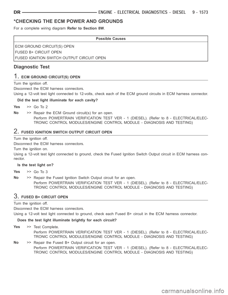
*CHECKING THE ECM POWER AND GROUNDS
For a complete wiring diagramRefer to Section 8W.
Possible Causes
ECM GROUND CIRCUIT(S) OPEN
FUSED B+ CIRCUIT OPEN
FUSED IGNITION SWITCH OUTPUT CIRCUIT OPEN
Diagnostic Test
1.ECM GROUND CIRCUIT(S) OPEN
Turn the ignition off.
Disconnect the ECM harness connectors.
Using a 12-volt test light connected to 12-volts, check each of the ECM ground circuits in ECM harness connector.
Did the test light illuminate for each cavity?
Ye s>>
Go To 2
No>>
Repair the ECM Ground circuit(s) for an open.
Perform POWERTRAIN VERIFICATION TEST VER - 1 (DIESEL). (Refer to 8 - ELECTRICAL/ELEC-
TRONIC CONTROL MODULES/ENGINE CONTROL MODULE - DIAGNOSIS AND TESTING)
2.FUSED IGNITION SWITCH OUTPUT CIRCUIT OPEN
Turn the ignition off.
Disconnect the ECM harness connectors.
Turn the ignition on.
Using a 12-volt test light connected to ground, check the Fused Ignition Switch Output circuit in ECM harness con-
nector.
Is the test light on?
Ye s>>
Go To 3
No>>
Repair the Fused Ignition Switch Output circuit for an open.
Perform POWERTRAIN VERIFICATION TEST VER - 1 (DIESEL). (Refer to 8 - ELECTRICAL/ELEC-
TRONIC CONTROL MODULES/ENGINE CONTROL MODULE - DIAGNOSIS AND TESTING)
3.FUSED B+ CIRCUIT OPEN
Turn the ignition off.
Disconnect the ECM harness connectors.
Using a 12-volt test light connected to ground, check each Fused B+ circuitin the ECM harness connector.
Does the test light illuminatebrightly for each circuit?
Ye s>>
Te s t C o m p l e t e .
Perform POWERTRAIN VERIFICATION TEST VER - 1 (DIESEL). (Refer to 8 - ELECTRICAL/ELEC-
TRONIC CONTROL MODULES/ENGINE CONTROL MODULE - DIAGNOSIS AND TESTING)
No>>
Repair the Fused B+ Output circuit for an open.
Perform POWERTRAIN VERIFICATION TEST VER - 1 (DIESEL). (Refer to 8 - ELECTRICAL/ELEC-
TRONIC CONTROL MODULES/ENGINE CONTROL MODULE - DIAGNOSIS AND TESTING)
Page 884 of 5267

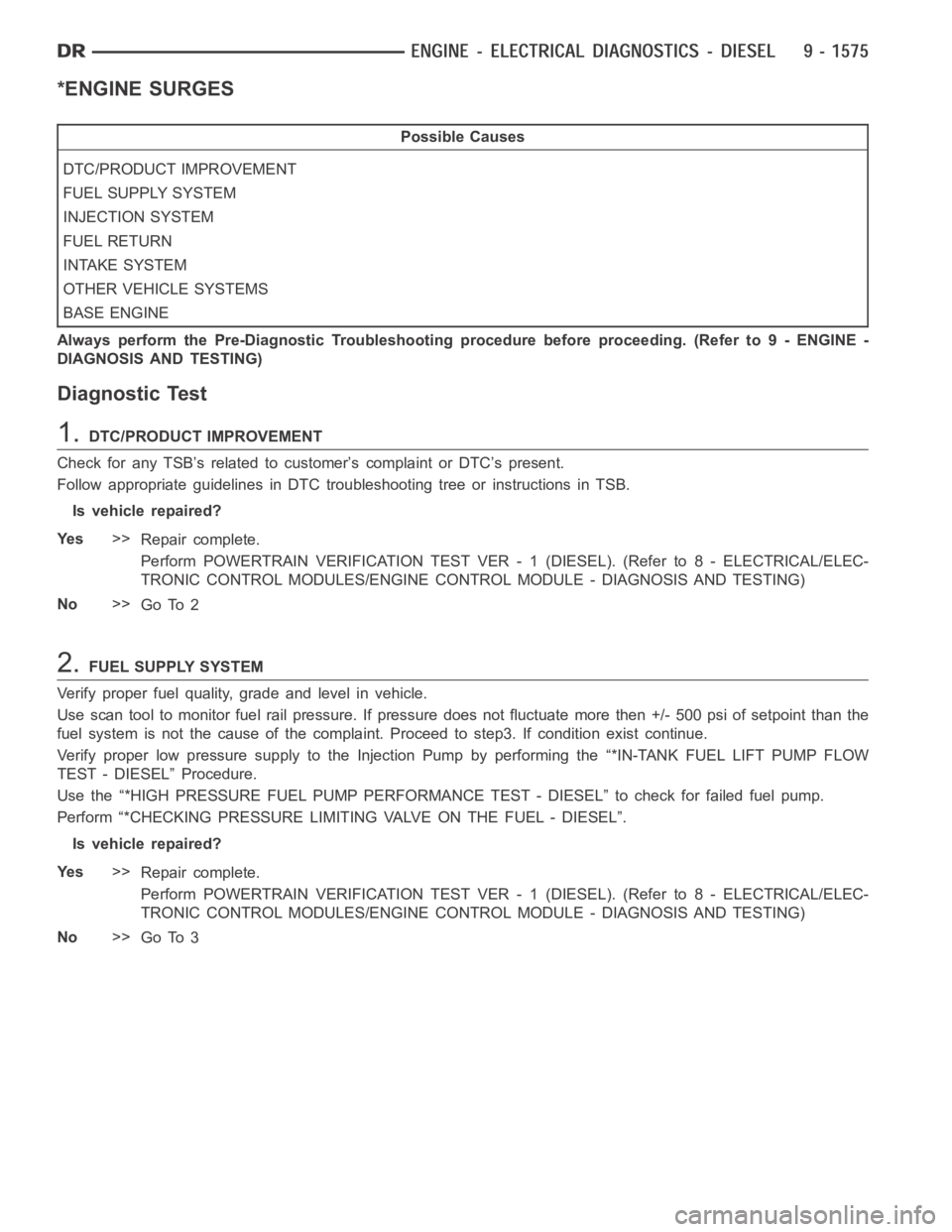
*ENGINE SURGES
Possible Causes
DTC/PRODUCT IMPROVEMENT
FUEL SUPPLY SYSTEM
INJECTION SYSTEM
FUEL RETURN
INTAKE SYSTEM
OTHER VEHICLE SYSTEMS
BASE ENGINE
Always perform the Pre-Diagnostic Troubleshooting procedure before proceeding. (Refer to 9 - ENGINE -
DIAGNOSIS AND TESTING)
Diagnostic Test
1.DTC/PRODUCT IMPROVEMENT
Check for any TSB’s related to customer’s complaint or DTC’s present.
Follow appropriate guidelines in DTC troubleshooting tree or instructions in TSB.
Is vehicle repaired?
Ye s>>
Repair complete.
Perform POWERTRAIN VERIFICATION TEST VER - 1 (DIESEL). (Refer to 8 - ELECTRICAL/ELEC-
TRONIC CONTROL MODULES/ENGINE CONTROL MODULE - DIAGNOSIS AND TESTING)
No>>
Go To 2
2.FUEL SUPPLY SYSTEM
Verify proper fuel quality, grade and level in vehicle.
Use scan tool to monitor fuel rail pressure. If pressure does not fluctuatemore then +/- 500 psi of setpoint than the
fuel system is not the cause of the complaint. Proceed to step3. If condition exist continue.
Verify proper low pressure supply to the Injection Pump by performing the “*IN-TANK FUEL LIFT PUMP FLOW
TEST - DIESEL” Procedure.
Use the “*HIGH PRESSURE FUEL PUMP PERFORMANCE TEST - DIESEL” to check for failed fuel pump.
Perform “*CHECKING PRESSURE LIMITING VALVE ON THE FUEL - DIESEL”.
Is vehicle repaired?
Ye s>>
Repair complete.
Perform POWERTRAIN VERIFICATION TEST VER - 1 (DIESEL). (Refer to 8 - ELECTRICAL/ELEC-
TRONIC CONTROL MODULES/ENGINE CONTROL MODULE - DIAGNOSIS AND TESTING)
No>>
Go To 3
Page 885 of 5267

3.INJECTION SYSTEM
Perform “*INJECTOR RETURN FLOW TEST”. If okay continue.
Check for correct injectors and injector shims.
Visuslly inspect injector wire nuts and pass through connectors for damageorcorrosion.
Is vehicle repaired?
Ye s>>
Repair complete.
Perform POWERTRAIN VERIFICATION TEST VER - 1 (DIESEL). (Refer to 8 - ELECTRICAL/ELEC-
TRONIC CONTROL MODULES/ENGINE CONTROL MODULE - DIAGNOSIS AND TESTING)
No>>
Go To 4
4.FUEL RETURN
Check for kinked or restricted fuel return lines.
Check fuel tank venting.
Is vehicle repaired?
Ye s>>
Repair complete.
Perform POWERTRAIN VERIFICATION TEST VER - 1 (DIESEL). (Refer to 8 - ELECTRICAL/ELEC-
TRONIC CONTROL MODULES/ENGINE CONTROL MODULE - DIAGNOSIS AND TESTING)
No>>
Go To 5
5.INTAKE SYSTEM
Check for inlet restriction, inspect air filter for excessive dirt/debris. Verify air intake lines are not kinked or restricted.
Check for air system leaks. Perform “*INTAKE AIR SYSTEM PRESSURE TEST - DIESEL”.
Inspect Turbocharger for wheel clearance and proper wastegate operation.
Is vehicle repaired?
Ye s>>
Repair complete.
Perform POWERTRAIN VERIFICATION TEST VER - 1 (DIESEL). (Refer to 8 - ELECTRICAL/ELEC-
TRONIC CONTROL MODULES/ENGINE CONTROL MODULE - DIAGNOSIS AND TESTING)
No>>
Go To 6
6.OTHER VEHICLE SYSTEMS
Verify proper operation of the Transmission Clutch.
Verify proper operation of the Transmission.
Verify proper operation of the Vehicle brakes (check for dragging).
Verify proper operation of the Cooling fan operation cycle time.
Verify proper operation of the Engine driven accessories.
Verify proper operation of the Accelerator pedal (restricted or out of calibration).
Is vehicle repaired?
Ye s>>
Repair complete.
Perform POWERTRAIN VERIFICATION TEST VER - 1 (DIESEL). (Refer to 8 - ELECTRICAL/ELEC-
TRONIC CONTROL MODULES/ENGINE CONTROL MODULE - DIAGNOSIS AND TESTING)
No>>
Go To 7