2006 DODGE RAM SRT-10 check engine
[x] Cancel search: check enginePage 984 of 5267

5.(K22) TP SENSOR SIGNAL CIRCUIT SHORTED TO THE (F855) 5-VOLT SUPPLY CIRCUIT
Measure the resistance between the (K22) TP Sensor Signal circuit and
the (F855) 5-volt Supply circuit in the TP Sensor harness connector.
Istheresistancebelow100ohms?
Ye s>>
Repair the short between the (F855) 5-volt Supply circuit
and the (K22) TP Sensor Signal circuit.
Perform the POWERTRAIN VERIFICATION TEST. (Refer to
9 - ENGINE - STANDARD PROCEDURE)
No>>
Go To 6
6.(K900) SENSOR GROUND CIRCUIT OPEN
Measure the resistance of the (K900) Sensor ground circuit from the TP
Sensor harness connector to the PCM harness connector.
Is the resistance below 5.0 ohms?
Ye s>>
Go To 7
No>>
Repair the open in the (K900) Sensor ground circuit.
Perform the POWERTRAIN VERIFICATION TEST. (Refer to
9 - ENGINE - STANDARD PROCEDURE)
7.PCM
NOTE: Before continuing, check the PCM harness connector terminals for corrosion, damage, or terminal
push out. Repair as necessary.
Using the schematics as a guide, inspect the wire harness and connectors. Pay particular attention to all Power and
Ground circuits.
Were there any problems found?
Ye s>>
Repair as necessary.
Perform the POWERTRAIN VERIFICATION TEST. (Refer to 9 - ENGINE - STANDARD PROCEDURE)
No>>
Replace and program the Powertrain Control Module per Service Information.
Perform the POWERTRAIN VERIFICATION TEST. (Refer to 9 - ENGINE - STANDARD PROCEDURE)
Page 987 of 5267

Theory of Operation
The engine coolant temperature sensor is a negative temperature coefficient thermistor-type sensor whose resis-
tance varies inversely with temperature. At cold temperatures the sensorresistance is high so the voltage is high.
As the coolant temperature increases the resistance decreases and the voltage becomes low. The INSUFFICIENT
COOLANT TEMP FOR CLOSED-LOOP FUEL CONTROL determines if the engine coolant temperature will reach
theclosedloopfuelingcontroltemperaturelimitinaregulatedtimeafterstart.
When Monitored:
With battery voltage greater than 10.4 volts and after engine is started.
Set Condition:
The engine temperature does not go above -10°C (15°F). Failure time depends on start-up coolant tempera-
ture and ambient temperature. (i.e. 2 minutes for a start temp of -10°C (15°F) or up to 10 minutes for a vehicle
with a start-up temp of -28°C (5°F). Two Trip Fault. Three good trips to turnoff the MIL.
Possible Causes
LOW COOLANT LEVEL
THERMOSTAT
ECT SENSOR
Always perform the Pre-Diagnostic Troubleshooting procedure before proceeding. (Refer to 9 - ENGINE -
DIAGNOSIS AND TESTING).
Diagnostic Test
1.CHECKING COOLANT LEVEL AND CONDITION
Ignition on, engine not running.
With a scan tool, read DTCs.
NOTE: If an Engine Coolant Temperature (ECT) DTC is set along with this code, diagnose the ECT DTC first.
NOTE: Inspect the ECT terminals and related PCM terminals. Make sure the terminals are free from corro-
sion and damage.
NOTE: The best way to diagnose this DTC is to allow the vehicle to sit overnight outside in order to have
a totally cold soaked engine.
NOTE: Extremely cold outside ambient temperatures may have caused this DTCtoset.
WARNING: Never open the cooling system when the engine is hot. The system isunder pressure. Extreme
burns or scalding may result. Failure to follow these instructions can result in personal injury or death.
Allow the engine to cool before opening the cooling system.
Inspect the coolant system for proper level and condition.
Is the coolant level and condition OK?
Ye s>>
Go To 2
No>>
Inspect the vehicle for a coolant leak, make the appropriate repairs, and add the correct amount of
coolant.
Perform the POWERTRAIN VERIFICATION TEST. (Refer to 9 - ENGINE - STANDARD PROCEDURE)
Page 991 of 5267

3.(K41) O2 SENSOR 1/1 SIGNAL CIRCUIT SHORTED TO GROUND
Turn the ignition off.
Disconnect the C1 PCM harness connector.
Measure the resistance between ground and the (K41) O2 Sensor 1/1
Signal circuit at the 1/1 O2 Sensor harness connector.
Istheresistancebelow100ohms?
Ye s>>
Repair the short to ground in the (K41) O2 Sensor 1/1Sig-
nal circuit.
Perform the POWERTRAIN VERIFICATION TEST. (Refer to
9 - ENGINE - STANDARD PROCEDURE)
No>>
Go To 4
4.(K41) O2 SENSOR 1/1 SIGNAL CIRCUIT SHORTED TO (K900) SENSOR GROUND CIRCUIT
Measure the resistance between the (K41) O2 Sensor 1/1 Signal circuit
and the (K900) Sensor ground circuit at the 1/1 O2 Sensor harness
connector.
Istheresistancebelow100ohms?
Ye s>>
Repair the short between the (K900) Sensor ground circuit
and the (K41) O2 Sensor 1/1 Signal circuit.
Perform the POWERTRAIN VERIFICATION TEST. (Refer to
9 - ENGINE - STANDARD PROCEDURE)
No>>
Go To 5
5.PCM
NOTE: Before continuing, check the PCM harness connector terminals for corrosion, damage, or terminal
push out. Repair as necessary.
Using the schematics as a guide, inspect the wire harness and connectors. Pay particular attention to all Power and
Ground circuits.
Were there any problems found?
Ye s>>
Repair as necessary.
Perform the POWERTRAIN VERIFICATION TEST. (Refer to 9 - ENGINE - STANDARD PROCEDURE)
No>>
Replace and program the Powertrain Control Module per Service Information.
Perform the POWERTRAIN VERIFICATION TEST. (Refer to 9 - ENGINE - STANDARD PROCEDURE)
Page 996 of 5267

7.(K99) O2 SENSOR 1/1 HEATER CONTROL CIRCUIT OPEN
Turn the ignition off.
Disconnect the C3 PCM harness connector.
Measure the resistance of the (K99) O2 Sensor 1/1 Heater Control cir-
cuit from the O2 Sensor harness connector to the PCM harness con-
nector.
Is the resistance below 5.0 ohms?
Ye s>>
Go To 8
No>>
Repair the open in the (K99) O2 Sensor 1/1 Heater Control
Circuit (PWM) circuit.
Perform the POWERTRAIN VERIFICATION TEST. (Refer to
9 - ENGINE - STANDARD PROCEDURE)
8.PCM
NOTE: Before continuing, check the PCM harness connector terminals for corrosion, damage, or terminal
push out. Repair as necessary.
Using the schematics as a guide, inspect the wire harness and connectors. Pay particular attention to all Power and
Ground circuits.
Were there any problems found?
Ye s>>
Repair as necessary.
Perform the POWERTRAIN VERIFICATION TEST. (Refer to 9 - ENGINE - STANDARD PROCEDURE)
No>>
Replace and program the Powertrain Control Module per Service Information.
Perform the POWERTRAIN VERIFICATION TEST. (Refer to 9 - ENGINE - STANDARD PROCEDURE)
Page 998 of 5267

When Monitored:
With ECT greater than 147°F, after reaching a vehicle speed of 10 mph, and the throttle remaining open (off
idle) for 2 minutes, bring the vehicle to a stop and allow the engine to idle with the transmission in DRIVE.
Set Condition:
The oxygen sensor signal voltage is switching from below 0.27 of a volt to above 0.62 of a volt and back fewer
times than required.
Possible Causes
EXHAUST LEAK
(K41) O2 1/1 SIGNAL CIRCUIT
(K900) SENSOR GROUND CIRCUIT
O2 SENSOR
Always perform the Pre-Diagnostic Troubleshooting procedure before proceeding. (Refer to 9 - ENGINE -
DIAGNOSIS AND TESTING).
Diagnostic Test
1.ACTIVE DTC
NOTE: Check for contaminants that may have damaged the O2 Sensor: contaminated fuel, unapproved sil-
icone, oil and coolant.
Ignition on, engine not running.
NOTE: After the repairs have been made, verify proper O2 Sensor operation.If all the O2 Sensor voltage
readings have not returned to normal, follow the diagnostic procedure forthe remaining O2 Sensors.
With a scan tool, read DTCs.
Is the DTC active at this time?
Ye s>>
Go To 2
No>>
Refer to the INTERMITTENT CONDITION Symptom. (Refer to 9 - ENGINE - DIAGNOSIS AND TEST-
ING)
2.EXHAUST LEAK
Start the engine.
Inspect the exhaust system for leaks between the engine and the O2 Sensors.
Are there any exhaust leaks?
Ye s>>
Repair or replace the leaking exhaust parts as necessary.
Perform the POWERTRAIN VERIFICATION TEST. (Refer to 9 - ENGINE - STANDARD PROCEDURE)
No>>
Go To 3
3.(K41) O2 1/1 SIGNAL CIRCUIT VOLTAGE DROP
Turn the ignition off.
While backprobing, measure the voltage of the (K41) O2 Sensor 1/1 Signal circuit between the 1/1 O2 Sensor har-
ness connector and PCM harness connector.
NOTE: Make sure the voltmeter leads meet the terminals in the connector andthat there is good terminal to
wire connection and are connected for positive polarity.
Start the engine.
Page 1002 of 5267

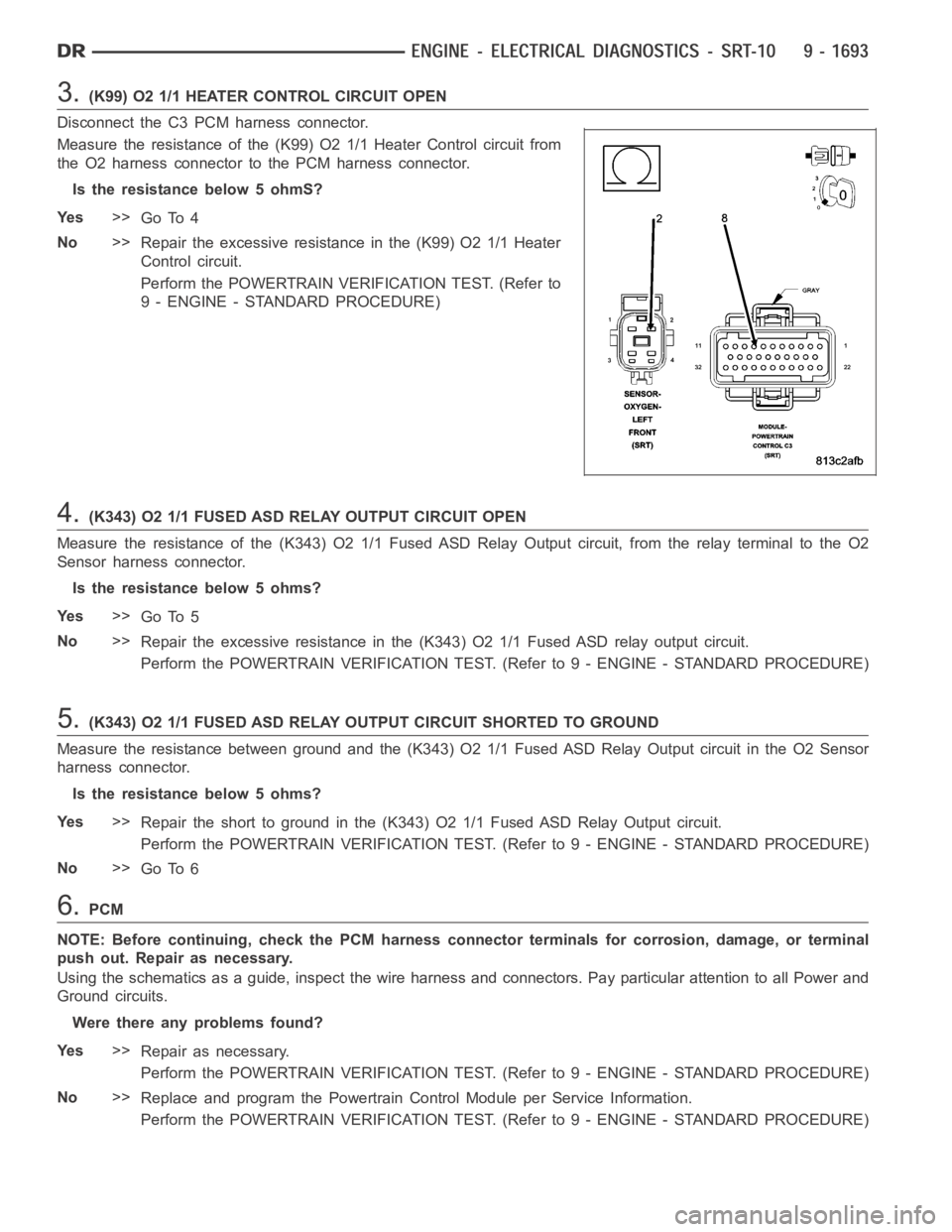
3.(K99) O2 1/1 HEATER CONTROL CIRCUIT OPEN
Disconnect the C3 PCM harness connector.
Measure the resistance of the (K99) O2 1/1 Heater Control circuit from
the O2 harness connector to the PCM harness connector.
Is the resistance below 5 ohmS?
Ye s>>
Go To 4
No>>
Repair the excessive resistance in the (K99) O2 1/1 Heater
Control circuit.
Perform the POWERTRAIN VERIFICATION TEST. (Refer to
9 - ENGINE - STANDARD PROCEDURE)
4.(K343) O2 1/1 FUSED ASD RELAY OUTPUT CIRCUIT OPEN
Measure the resistance of the (K343) O2 1/1 Fused ASD Relay Output circuit,from the relay terminal to the O2
Sensor harness connector.
Is the resistance below 5 ohms?
Ye s>>
Go To 5
No>>
Repair the excessive resistance in the (K343) O2 1/1 Fused ASD relay outputcircuit.
Perform the POWERTRAIN VERIFICATION TEST. (Refer to 9 - ENGINE - STANDARD PROCEDURE)
5.(K343) O2 1/1 FUSED ASD RELAY OUTPUT CIRCUIT SHORTED TO GROUND
Measure the resistance between ground and the (K343) O2 1/1 Fused ASD RelayOutput circuit in the O2 Sensor
harness connector.
Is the resistance below 5 ohms?
Ye s>>
Repair the short to ground in the (K343) O2 1/1 Fused ASD Relay Output circuit.
Perform the POWERTRAIN VERIFICATION TEST. (Refer to 9 - ENGINE - STANDARD PROCEDURE)
No>>
Go To 6
6.PCM
NOTE: Before continuing, check the PCM harness connector terminals for corrosion, damage, or terminal
push out. Repair as necessary.
Using the schematics as a guide, inspect the wire harness and connectors. Pay particular attention to all Power and
Ground circuits.
Were there any problems found?
Ye s>>
Repair as necessary.
Perform the POWERTRAIN VERIFICATION TEST. (Refer to 9 - ENGINE - STANDARD PROCEDURE)
No>>
Replace and program the Powertrain Control Module per Service Information.
Perform the POWERTRAIN VERIFICATION TEST. (Refer to 9 - ENGINE - STANDARD PROCEDURE)
Page 1005 of 5267

4.(K127) O2 HEATER RELAY CONTROL CIRCUIT OPEN
Turn the ignition off.
Disconnect the PCM harness connectors.
Measure the resistance of the (K127) O2 Heater Relay Control circuit from the PDC (Heater Relay) connector to the
PCM harness connector.
Is the resistance below 5.0 ohms?
Ye s>>
Go To 5
No>>
Repair the open in the (K127) O2 Heater Relay Control circuit.
Perform POWERTRAIN VERIFICATION TEST. (Refer to 9 - ENGINE - STANDARD PROCEDURE)
5.(K127) O2 HEATER RELAY CONTROL CIRCUIT SHORTED TO GROUND
Measure the resistance between ground and the (K127) O2 Heater Relay Control circuit at the PDC connector.
Istheresistancebelow100ohms?
Ye s>>
Repair the short to ground in the (K127) O2 Sensor Heater Relay Control circuit.
Perform POWERTRAIN VERIFICATION TEST. (Refer to 9 - ENGINE - STANDARD PROCEDURE)
No>>
Go To 6
6.O2 HEATER ELEMENT
NOTE: Allow the O2 Sensor to cool to room temperature.
Disconnect the O2 Sensor harness connector.
Measure the resistance across the O2 Sensor Heater element component side.
NOTE: The resistance value will increase with warmer temperatures.
Is the resistance between 4.0 and 5.0 ohms at 70° F (21.1°C)?
Ye s>>
Go To 7
No>>
Replace the O2 Sensor.
Perform POWERTRAIN VERIFICATION TEST. (Refer to 9 - ENGINE - STANDARD PROCEDURE)
7.PCM
NOTE: Before continuing, check the PCM harness connector terminals for corrosion, damage, or terminal
push out. Repair as necessary.
Using the schematics as a guide, inspect the wire harness and connectors. Pay particular attention to all Power and
Ground circuits.
If there are not possible causes remaining, view repair.
Repair
Replace and program the Powertrain Control Module per Service Information.
Perform POWERTRAIN VERIFICATION TEST. (Refer to 9 - ENGINE - STANDARD PROCEDURE)
Page 1009 of 5267

6.PCM
NOTE: Before continuing, check the PCM harness connector terminals for corrosion, damage, or terminal
push out. Repair as necessary.
Using the schematics as a guide, inspect the wire harness and connectors. Pay particular attention to all Power and
Ground circuits.
Were there any problems found?
Ye s>>
Repair as necessary.
Perform the POWERTRAIN VERIFICATION TEST. (Refer to 9 - ENGINE - STANDARD PROCEDURE)
No>>
Replace and program the Powertrain Control Module per Service Information.
Perform the POWERTRAIN VERIFICATION TEST. (Refer to 9 - ENGINE - STANDARD PROCEDURE)