2006 DODGE RAM SRT-10 wiring
[x] Cancel search: wiringPage 882 of 5267
*CHECKING THE ECM POWER AND GROUNDS
For a complete wiring diagramRefer to Section 8W.
Possible Causes
ECM GROUND CIRCUIT(S) OPEN
FUSED B+ CIRCUIT OPEN
FUSED IGNITION SWITCH OUTPUT CIRCUIT OPEN
Diagnostic Test
1.ECM GROUND CIRCUIT(S) OPEN
Turn the ignition off.
Disconnect the ECM harness connectors.
Using a 12-volt test light connected to 12-volts, check each of the ECM ground circuits in ECM harness connector.
Did the test light illuminate for each cavity?
Ye s>>
Go To 2
No>>
Repair the ECM Ground circuit(s) for an open.
Perform POWERTRAIN VERIFICATION TEST VER - 1 (DIESEL). (Refer to 8 - ELECTRICAL/ELEC-
TRONIC CONTROL MODULES/ENGINE CONTROL MODULE - DIAGNOSIS AND TESTING)
2.FUSED IGNITION SWITCH OUTPUT CIRCUIT OPEN
Turn the ignition off.
Disconnect the ECM harness connectors.
Turn the ignition on.
Using a 12-volt test light connected to ground, check the Fused Ignition Switch Output circuit in ECM harness con-
nector.
Is the test light on?
Ye s>>
Go To 3
No>>
Repair the Fused Ignition Switch Output circuit for an open.
Perform POWERTRAIN VERIFICATION TEST VER - 1 (DIESEL). (Refer to 8 - ELECTRICAL/ELEC-
TRONIC CONTROL MODULES/ENGINE CONTROL MODULE - DIAGNOSIS AND TESTING)
3.FUSED B+ CIRCUIT OPEN
Turn the ignition off.
Disconnect the ECM harness connectors.
Using a 12-volt test light connected to ground, check each Fused B+ circuitin the ECM harness connector.
Does the test light illuminatebrightly for each circuit?
Ye s>>
Te s t C o m p l e t e .
Perform POWERTRAIN VERIFICATION TEST VER - 1 (DIESEL). (Refer to 8 - ELECTRICAL/ELEC-
TRONIC CONTROL MODULES/ENGINE CONTROL MODULE - DIAGNOSIS AND TESTING)
No>>
Repair the Fused B+ Output circuit for an open.
Perform POWERTRAIN VERIFICATION TEST VER - 1 (DIESEL). (Refer to 8 - ELECTRICAL/ELEC-
TRONIC CONTROL MODULES/ENGINE CONTROL MODULE - DIAGNOSIS AND TESTING)
Page 890 of 5267
*FUEL HEATER THERMOSTAT TEST
Diagnostic Test
1.FUEL HEATER THERMOSTAT TEST
To check the operating resistance levels on the thermostat and fuel heaterperform the following:
1. Unplug the wiring harness from the thermostat.
2. Check the resistance across the two pins of the thermostat with an Ohm meter.
3. The ambient temperature must be below the
Circuit close temperature; 1° +/- 3° Cto perform this check.
4. If necessary, induce this ambient temperature by placing ice packs on the thermostat to produce an
effective
ambient temperature
below the circuit close temperature.
5. The resistance across the two pins should be within the range of 0.3 Ohms to 0.45 Ohms for a properly operating
thermostat and heater.
6. If the resistance from step 2 is out of range, remove the thermostat and check the resistance across the terminal
connections of the heater (the heater can be checked at room temperatures).
7. The resistance across the terminal pins of the heater should be within the same range of step 2.
8. Replace the heater if resistance is not within the proper operation range.
9. Replace the heater if resistance is not within the proper operation range. Re-install the thermostat with a new
o-ring.
10. If the heater resistance is within the proper operating.
11. Circuit close temperature; 1° +/- 3° C
12. Circuit open temperature; 18° +/- 4° C
13. Fuel Heater Thermostat 0.3 - 0.45 Ohms at less than 1 degree C
14. Fuel Heater 0.3 - 0.45 Ohms at room temperature
View Repair
Repair
Te s t c o m p l e t e .
Perform POWERTRAIN VERIFICATION TEST VER - 1 (DIESEL). (Refer to 8 - ELECTRICAL/ELEC-
TRONIC CONTROL MODULES/ENGINE CONTROL MODULE - DIAGNOSIS AND TESTING)
Page 892 of 5267

1.
1. Using the Scan tool, check for DTCs. Troubleshoot any active DTCs beforeperforming this test.
2. Disconnect the wiring harness from the lift pump at the fuel tank module connector and inspect the pins for
damage. Fix or replace any damaged component.
3. Connect a voltmeter between the fuel lift pump supply and return pins at the fuel tank module connector.
4. Turn the ignition to the on position. Use the Scan tool to actuate the fuellift pump, record the voltage on the
voltmeter.
5. If the voltage is greater than 11.5 volts, go to step 14. If the voltage is lessthan11.5volts,gotostep6
6. Using a voltmeter, measure the battery voltage to determine that the voltage is greater than 11.5 volts. If the
voltage is greater than 11.5 volts, go to step 7. If the voltage is not greater than 11.5 volts, troubleshoot for low
battery voltage.
7. Remove the fuel lift pump relay from the PDC. Use a voltmeter to measure the voltage at the fuel lift pump relay
voltage supply pin in the PDC. If the voltage is greater than 11.5 volts, go to step 8. If the voltage is not greater than
11.5 volts, fix or replace the harness.
8. Remove the fuel lift pump relay from the PDC. Install a spare relay in place of the fuel lift pump relay. Using the
Scan tool, actuate the fuel lift pump. Use a voltmeter to measure the voltage between the fuel lift pump supply and
return pins at the fuel tank module connector while the fuel lift pump is actuated. If the voltage is greater than 11.5
volts, replace the fuel lift pump relay. If the voltage is not greater than 11.5volts,gotostep9.
9. Disconnect the wiring harness from the fuel tank module. Remove the liftpump relay from the PDC. Using an
Ohmmeter, measure the resistance of the fuel lift pump power supply wire between the PDC relay output pin and
the fuel tank module connector. If the resistance is less than 10 ohms, go tostep 10. If it is greater than 10 ohms,
fix or replace the harness.
10. Disconnect the wiring harness from the fuel tank module. Remove the fuel lift pump relay from the PDC. Using
a voltmeter, measure the voltage between battery negative and the fuel lift pump power supply wire at the fuel
module connector. If the voltage is less than 1 volt, go to step 11. If the voltage is greater than 1 volt, fix or replace
the harness.
11. Disconnect the wiring harness from the fuel tank module. Remove the fuel lift pump relay from the PDC. Using
an ohmmeter, measure the resistance between battery negative and the fuellift pump power supply wire at the fuel
module connector. If the resistance is less than 10 ohms, fix or replace theharness. If the resistance is greater than
10 ohms, go to step 12.
12. Disconnect the wiring harness from the fuel tank module. Using an Ohmmeter, measure the resistance of the
fuel lift pump ground wire between the fuel tank module connector and battery negative. If the resistance is less
than 10 ohms, go to step 13. If the resistance is greater than 10 ohms, fix or replace the harness.
13. Disconnect the wiring harness from the fuel tank module. Using a voltmeter, measure the voltage between the
fuel lift pump ground wire and battery negative. If the voltage is less than1 volt, go to step 14. If the voltage is
greater than 1 volt, fix or replace the harness.
14. Reconnect the lift pump connector.
FLOW TEST.
1. Remove the fuel pump supply banjo fitting from the fuel injection pump.
2. Install Miller Tool #9014 fuel system test fitting into the fuel injection pump.
3. Connect one end of a section of fuel hose to the test fitting.
4. Put the other end of the fuel hose into an empty fuel container.
5. Use the scan tool to actuate the fuel lift pump.
6. While the lift pump is running, move the fuel hose from the fuel canister into a 1000ml graduated cylinder for 10
seconds.
7. Read and record the amount of fuel in the graduated cylinder after 10 seconds.
8. If you have more than 430ml in the graduated cylinder after 10 seconds, the test has successfully passed.
9. If you have less than 430ml of fuel in the graduated cylinder, inspect thefuel supply line from the fuel tank to the
fuel filter housing and the fuel supply line between the fuel filter housing and the high pressure fuel pump for signs
of damage, replace as necessary. If no damage is found, replace the fuel filter and retest.
10.Verify the Screened Banjo Bolt at the outlet of the fuel filter is free ofdebris. If debris is found, rinse screen with
water, blow dry and reinstall. Retest vehicle. If flow meets specification then trace back the source of debris, if flow
is still below spec repair damaged component.
Page 898 of 5267
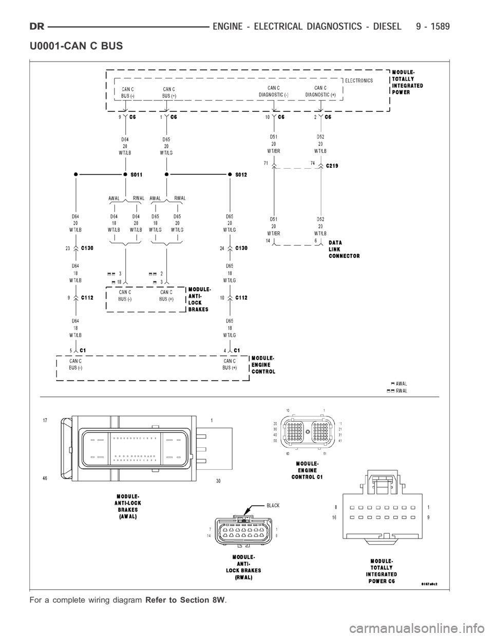
U0001-CAN C BUS
For a complete wiring diagramRefer to Section 8W.
Page 900 of 5267
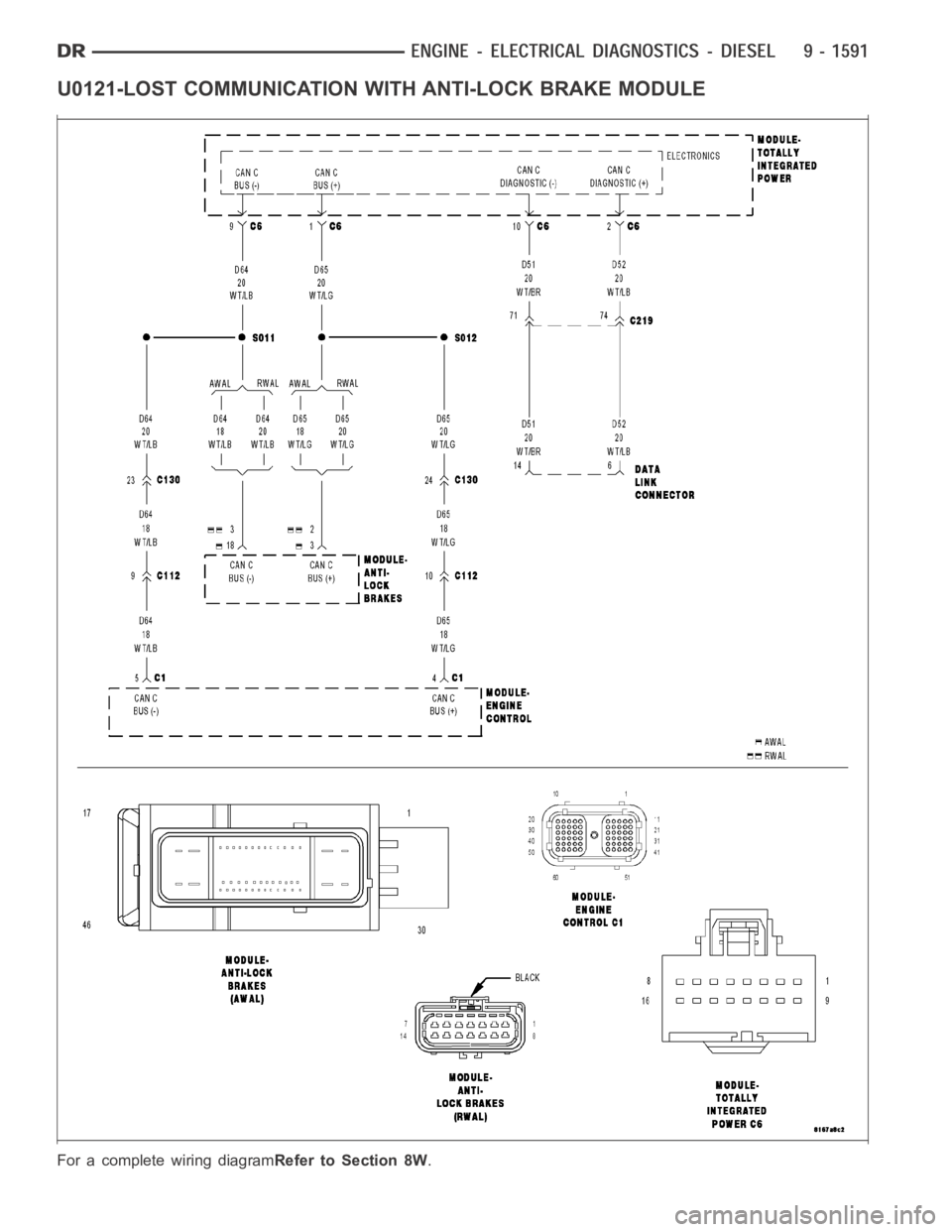
U0121-LOST COMMUNICATION WITH ANTI-LOCK BRAKE MODULE
For a complete wiring diagramRefer to Section 8W.
Page 902 of 5267
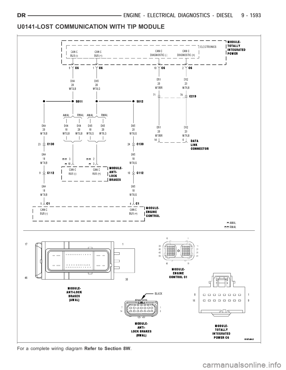
U0141-LOST COMMUNICATION WITH TIP MODULE
For a complete wiring diagramRefer to Section 8W.
Page 904 of 5267
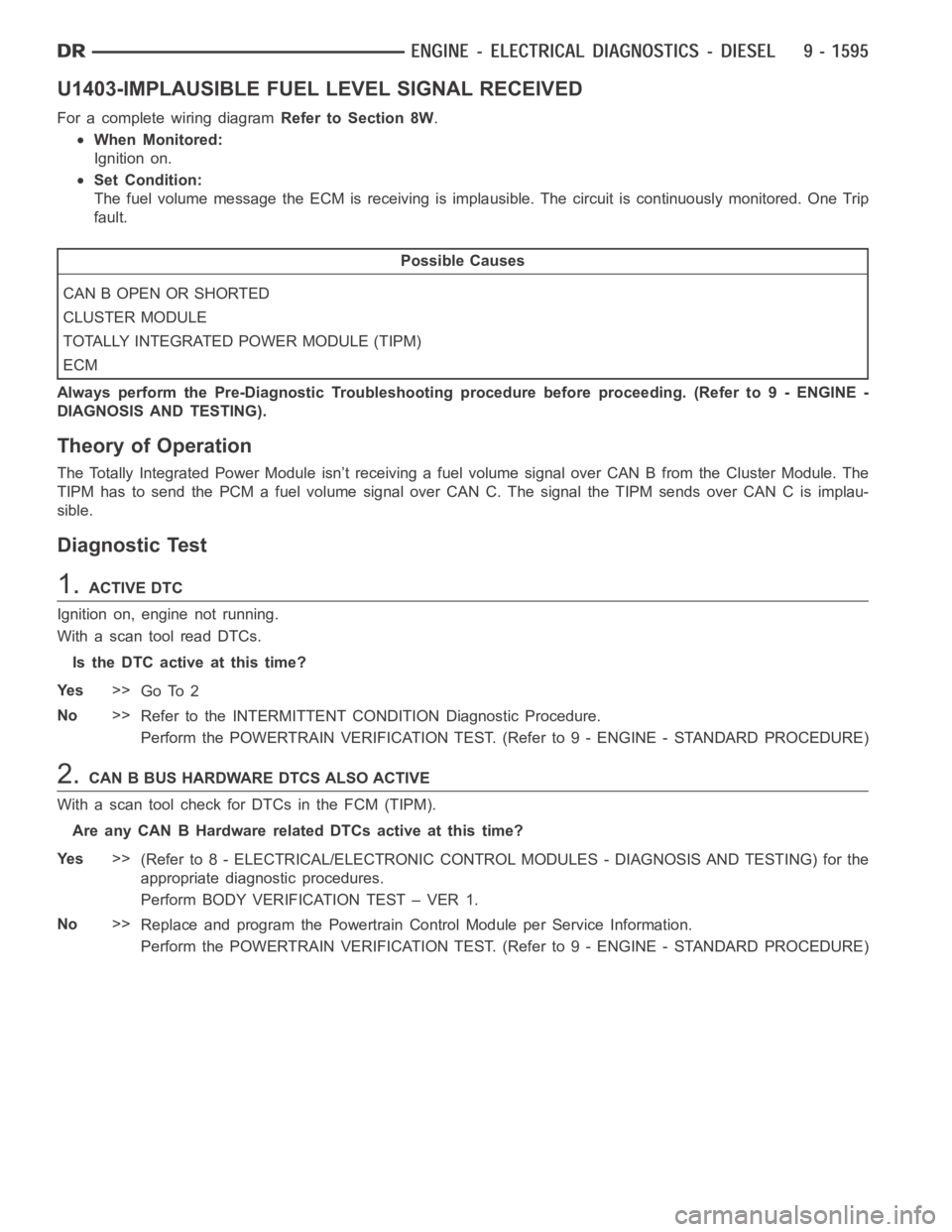
U1403-IMPLAUSIBLE FUEL LEVEL SIGNAL RECEIVED
For a complete wiring diagramRefer to Section 8W.
When Monitored:
Ignition on.
Set Condition:
The fuel volume message the ECM is receiving is implausible. The circuit iscontinuously monitored. One Trip
fault.
Possible Causes
CAN B OPEN OR SHORTED
CLUSTER MODULE
TOTALLY INTEGRATED POWER MODULE (TIPM)
ECM
Always perform the Pre-Diagnostic Troubleshooting procedure before proceeding. (Refer to 9 - ENGINE -
DIAGNOSIS AND TESTING).
Theory of Operation
The Totally Integrated Power Module isn’t receiving a fuel volume signal over CAN B from the Cluster Module. The
TIPM has to send the PCM a fuel volume signal over CAN C. The signal the TIPM sendsoverCANCisimplau-
sible.
Diagnostic Test
1.ACTIVE DTC
Ignition on, engine not running.
With a scan tool read DTCs.
Is the DTC active at this time?
Ye s>>
Go To 2
No>>
Refer to the INTERMITTENT CONDITION Diagnostic Procedure.
Perform the POWERTRAIN VERIFICATION TEST. (Refer to 9 - ENGINE - STANDARD PROCEDURE)
2.CAN B BUS HARDWARE DTCS ALSO ACTIVE
With a scan tool check for DTCs in the FCM (TIPM).
Are any CAN B Hardware related DTCs active at this time?
Ye s>>
(Refer to 8 - ELECTRICAL/ELECTRONIC CONTROL MODULES - DIAGNOSIS AND TESTING) for the
appropriate diagnostic procedures.
Perform BODY VERIFICATION TEST – VER 1.
No>>
Replace and program the Powertrain Control Module per Service Information.
Perform the POWERTRAIN VERIFICATION TEST. (Refer to 9 - ENGINE - STANDARD PROCEDURE)
Page 905 of 5267
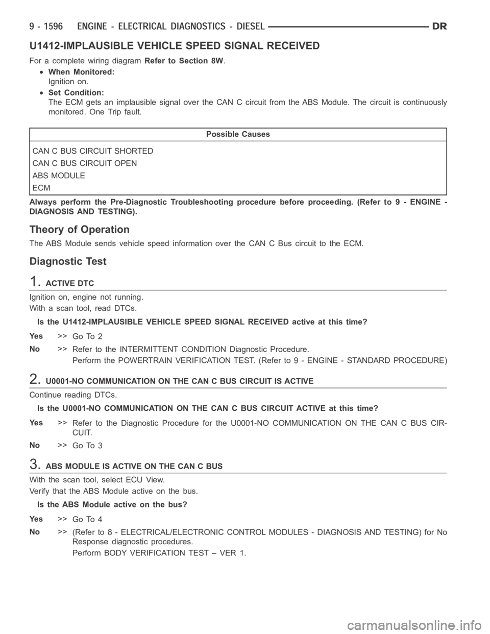
U1412-IMPLAUSIBLE VEHICLE SPEED SIGNAL RECEIVED
For a complete wiring diagramRefer to Section 8W.
When Monitored:
Ignition on.
Set Condition:
The ECM gets an implausible signal over the CAN C circuit from the ABS Module. The circuit is continuously
monitored. One Trip fault.
Possible Causes
CAN C BUS CIRCUIT SHORTED
CAN C BUS CIRCUIT OPEN
ABS MODULE
ECM
Always perform the Pre-Diagnostic Troubleshooting procedure before proceeding. (Refer to 9 - ENGINE -
DIAGNOSIS AND TESTING).
Theory of Operation
The ABS Module sends vehicle speed information over the CAN C Bus circuit tothe ECM.
Diagnostic Test
1.ACTIVE DTC
Ignition on, engine not running.
With a scan tool, read DTCs.
Is the U1412-IMPLAUSIBLE VEHICLE SPEED SIGNAL RECEIVED active at this time?
Ye s>>
Go To 2
No>>
Refer to the INTERMITTENT CONDITION Diagnostic Procedure.
Perform the POWERTRAIN VERIFICATION TEST. (Refer to 9 - ENGINE - STANDARD PROCEDURE)
2.U0001-NO COMMUNICATION ON THE CAN C BUS CIRCUIT IS ACTIVE
Continue reading DTCs.
Is the U0001-NO COMMUNICATION ON THE CAN C BUS CIRCUIT ACTIVE at this time?
Ye s>>
Refer to the Diagnostic Procedure for the U0001-NO COMMUNICATION ON THE CANCBUSCIR-
CUIT.
No>>
Go To 3
3.ABS MODULE IS ACTIVE ON THE CAN C BUS
With the scan tool, select ECU View.
Verify that the ABS Module active on the bus.
Is the ABS Module active on the bus?
Ye s>>
Go To 4
No>>
(Refer to 8 - ELECTRICAL/ELECTRONIC CONTROL MODULES - DIAGNOSIS AND TESTING) for No
Response diagnostic procedures.
Perform BODY VERIFICATION TEST – VER 1.