Page 803 of 5267

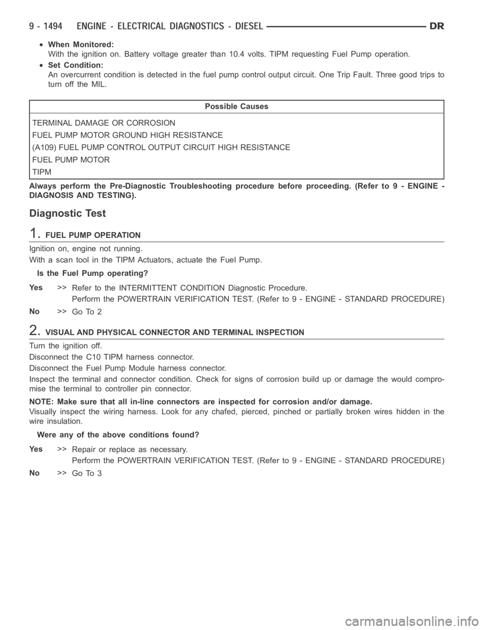
When Monitored:
With the ignition on. Battery voltage greater than 10.4 volts. TIPM requesting Fuel Pump operation.
Set Condition:
An overcurrent condition is detected in the fuel pump control output circuit. One Trip Fault. Three good trips to
turn off the MIL.
Possible Causes
TERMINAL DAMAGE OR CORROSION
FUEL PUMP MOTOR GROUND HIGH RESISTANCE
(A109) FUEL PUMP CONTROL OUTPUT CIRCUIT HIGH RESISTANCE
FUEL PUMP MOTOR
TIPM
Always perform the Pre-Diagnostic Troubleshooting procedure before proceeding. (Refer to 9 - ENGINE -
DIAGNOSIS AND TESTING).
Diagnostic Test
1.FUEL PUMP OPERATION
Ignition on, engine not running.
With a scan tool in the TIPM Actuators, actuate the Fuel Pump.
Is the Fuel Pump operating?
Ye s>>
Refer to the INTERMITTENT CONDITION Diagnostic Procedure.
Perform the POWERTRAIN VERIFICATION TEST. (Refer to 9 - ENGINE - STANDARD PROCEDURE)
No>>
Go To 2
2.VISUAL AND PHYSICAL CONNECTOR AND TERMINAL INSPECTION
Turn the ignition off.
Disconnect the C10 TIPM harness connector.
Disconnect the Fuel Pump Module harness connector.
Inspect the terminal and connector condition. Check for signs of corrosion build up or damage the would compro-
mise the terminal to controller pin connector.
NOTE: Make sure that all in-line connectors are inspected for corrosion and/or damage.
Visually inspect the wiring harness. Look for any chafed, pierced, pinched or partially broken wires hidden in the
wire insulation.
Were any of the above conditions found?
Ye s>>
Repair or replace as necessary.
Perform the POWERTRAIN VERIFICATION TEST. (Refer to 9 - ENGINE - STANDARD PROCEDURE)
No>>
Go To 3
Page 805 of 5267
P1652-J1850 SHORT TO GROUND
For a complete wiring diagramRefer to Section 8W.
Page 808 of 5267
P2121-PPS CONFORMANCE ERROR
For a complete wiring diagramRefer to Section 8W.
Page 809 of 5267

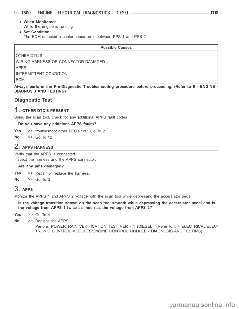
When Monitored:
While the engine is running
Set Condition:
The ECM detected a conformance error between PPS 1 and PPS 2
Possible Causes
OTHER DTC’S
WIRING HARNESS OR CONNECTOR DAMAGED
APPS
INTERMITTENT CONDITION
ECM
Always perform the Pre-Diagnostic Troubleshooting procedure before proceeding. (Refer to 9 - ENGINE -
DIAGNOSIS AND TESTING)
Diagnostic Test
1.OTHER DTC’S PRESENT
Using the scan tool, check for any additional APPS fault codes
Do you have any additiona APPS faults?
Ye s>>
troubleshoot other DTC’s first, Go To 2
No>>
Go To 12
2.APPS HARNESS
Verify that the APPS is connected.
Inspect the harness and the APPS connector.
Are any pins damaged?
Ye s>>
Repair or replace the harness.
No>>
Go To 3
3.APPS
Monitor the APPS 1 and APPS 2 voltage with the scan tool while depressing theacceralator pedal.
Is the voltage transition shown on the scan tool smooth while depressing the acceralator pedal and is
the voltage from APPS 1 twice as much as the voltage from APPS 2?
Ye s>>
Go To 4
No>>
Replace the APPS.
Perform POWERTRAIN VERIFICATION TEST VER - 1 (DIESEL). (Refer to 8 - ELECTRICAL/ELEC-
TRONIC CONTROL MODULES/ENGINE CONTROL MODULE - DIAGNOSIS AND TESTING)
Page 820 of 5267
P2122-PPS 1 VOLTAGE TOO LOW
For a complete wiring diagramRefer to Section 8W.
Page 825 of 5267
P2123-PPS 1 VOLTAGE TOO HIGH
For a complete wiring diagramRefer to Section 8W.
Page 829 of 5267
P2127-PPS 2 VOLTAGE TOO LOW
For a complete wiring diagramRefer to Section 8W.
Page 834 of 5267
P2128-PPS 2 VOLTAGE TOO HIGH
For a complete wiring diagramRefer to Section 8W.